1
DESCRIPTION AND USE OF CMT400 AND CMT656
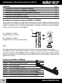
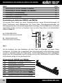
INDEX
Description and use of CMT400 and CMT656
Description and use of CMT400-1 and CMT400-2
Making dowel joints
Making screw joints
Work safety and Spare parts list
page
02
04
06
10
15
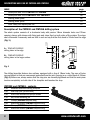
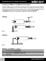
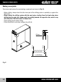
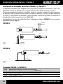
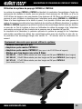
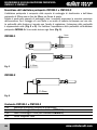
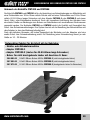
Description of the CMT400 and CMT656 drilling system
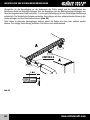
24mm
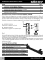
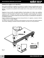
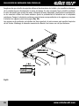
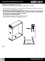
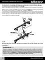
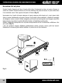
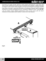
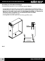
The whole system consists of a duralumin body with precise 18mm diameter holes and 32mm
spacing, clamps with clamps with fixing nuts and stops fixed on both sides of the system. The stops
can be removed if necessary and are built in such as way that the first dowel is 24mm from the edge
(Fig. 1).
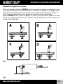
A... TEMPLATE SURFACE
drilling holes in the edge
B... TEMPLATE SURFACE
drilling holes in the larger surface
B
A
Fig. 1
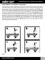
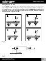
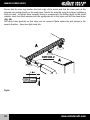
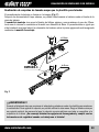
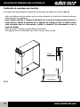
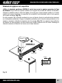
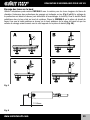
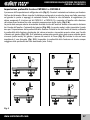
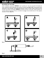
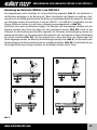
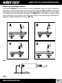
The drilling template features two surfaces equipped with a line of 18mm holes. The rows of holes
are positioned so that one component protrudes from the joint, forming a so- called facet of 0.8mm
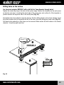
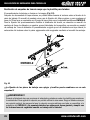
(Fig. 4). Before use, always ensure that the stop pins are correctly tightened and that the work piece
touches completely on both side of the template and touches the stop.
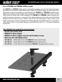
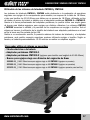
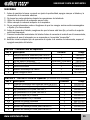
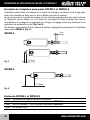
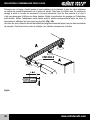
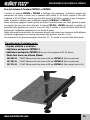
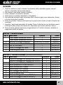
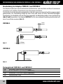
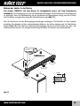
CMT400 and CMT656 - contents
1 pc
2 pc
2 pc
1 pc
2 pc
4 pc
3 pc
6 pc
2
Anodised duralumin drilling template
steel stop pins (Ø10x10mm)
M4x16mm countersunk philips screws
Ø8/18mm centering pin
Clamps (CMT400 template only)
M8x45mm screws (CMT400 template only)
Clamps (CMT656 template only)
M8x45mm screws (CMT656 template only)
www.cmtutensili.com