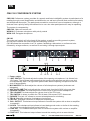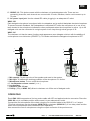
1
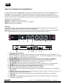
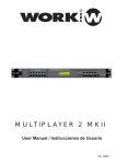
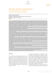
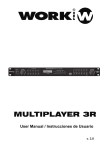
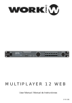
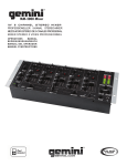
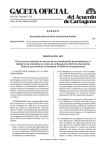
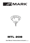
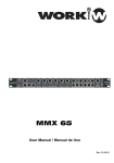
CMU 100
TEL VOLUME
PHONES VOLUME
User Manual / Manual de Uso
Rev 1.0
EN
WARNING:
TO REDUCE THE RISK OF ELECTRIC SHOCK, DO NOT REMOVE COVER
(OR BACK) NO USER SEVICEABLE PARTS INSIDE. REFER SERVICING
TO QUALIFIED PERSONNEL.
GRAPHICAL SYMBOLS EXPLANATION
This symbol, wherever used,alerts you to
the presence of un-isulated and dangerous
voltages within the product enclosure.
These are voltages that may be sufficient to
constitute the risk of electric shock.
This symbol, wherever used, alerts you to
important operating and maintenance
instructions. Please read.
WARNING:
TO REDUCE THE RISK OF FIRE OR ELECTRIC SHOCK, DO NOT EXPOSE
TO RAIN OR HUMIDITY. DO NOT REMOVE COVER. THIS PRODUCT IS
NOT INTENDED FOR USE OTHER THAN STATED.
1. Read instructions - All the safety and operating instructions
should be read before the unit is operated.
2. Retain instructions - The safety and operating instructions
should be retained for future reference.
3. Heed warnings - all warnings on the unit and in the
operating instructions should be adhered to.
4. Follow instructions - All operations and other instructions
should be followed.
5. Water & Moisture - The unit should not be used near
water, for example, near a bathtub, washbowl, kitchen
sink, laundry tub, in a wet basement, or near a swimming
pool, etc.
6. Carts & Stands - The unit should be used only with a cart
or stand that is recommended by the manufacturer.
A unit and cart combination should be moved
with care.
Quick stops, excessive force, and uneven
surfaces may cause the unit and cart combination
to overturn.
7. Grounding or Polarization - Precautions should be taken
so that the grounding or polarization is not defeated.
8. Ventilation - The unit should not be situated so that its
location or position does not interfere with its proper
ventilation. For example, the unit should not be situated
on a bed, sofa, rug, or similar surface, that may block the
ventilation openings; or placed in a built-in installation,
such as a bookcase or cabinet that may impede the flow
of air through the ventilation openings.
9. Heat - The unit should be situated away from heat sources
such as radiators, stoves, or other appliances that produces
heat.
10. Power Sourcers - The unit should be connected to a
power supply only of the type described in the operating
instructions or as marked on the unit.
11. Power Cord Protection - Power supply cord should be
routed so that they are not likely to be walked on or
pinched by items placed upon or against them, paying
particular attention to cords at plugs, convenience
receptacles, and the point where they exit the unit.
12. Cleaning - The unit should be cleaned only as
recommended by the manufacturer.
13. Nonuse Periods - The power cord of the unit should be
unplugged from the outlet when left unused for a long
period of time.
14. Object and Liquid entry - Care should be taken so that
objects do not fall into and liquids are not spilled into the
inside of the unit.
15. Damage Requiring Service - The unit should be serviced
by qualified service personnel when:
A. The power supply cord or the plug has been damaged;
or
B. Objects have fallen, or liquid has been spilled into the
unit; or
C. The unit has been exposed to rain; or
D. The unit does not appear to operate normally or
exhibits a marked change in performance.
E. The unit has been dropped, or the cabinet damaged.
16. Servicing - The user should not attempt to service the
unit beyond those means described in the operating
instructiuons. All other servicing should be referred to
qualified personnel.
PAG. 1
User Manual/Manual de Instrucciones
CMU 100
EN
CMU 100 CONFERENCE SYSTEM
CMU 100 Conference system provides of a speech and listen intelligibility system to participants of a
meeting through sound amplification and distribution, as well as to promote and conduict and orderly
and disciplined discussion. The participants are able to control their own microphones, although a
chairman has a priority facility that allows him to over rule other participants who may be speaking.
The system is composed by:
CMU 100 : Main and control unit
WCM10 C: Chairman microphone with priority control
WCM 10 D: Delegate microphone
CM 100
The main and control unit is the heart of the system. as well as providing power to system,
this unit also contains the central audio and switching controls.
CM 100 allows the connection to a P.A. system, facilitating a discussion or conference to be
followed by a large audience, as well as for recording it through tape outputs.
TEL VOLUME
8
7
PHONES VOLUME
6
5
4
3
2
1
14 12
1
2
16
10 9
15 14 13 11
1. Power switch
2. LIMIT SWITCH. This knob adjusts the state of the opening microphones. It is divided into
1/3/6 parts. The left three parts means that the opening microphones are at the non-shut
off automatically state. The right three parts means that the opening microphones can be
shut off automatically.
3. MIC MASTER.This knob adjust the volume of all microphone systems (chairman and
delegates)
4. AUX IN VOLUME.This knob adjusts the volume level from the AUX IN in the rear side.
5. PHONES VOLUME.This knob adjusts the volume level of the monitor headphones.
6. TEL VOLUME.This knob adjusts the volume level of the TEL input.
7. TEL SWITCH. It allows to switch the TEL IN state. ON:connect, OFF: disconnect.
8. PHONES.This jack 1/4" allows to connect a headphones for monitoring.
9. TEL IN. Standard connector for telephone input signal
10.TEL OUT. Standard connector for telephone output signal.
11. BAL. OUTPUT. This balanced output allows to connect the system with a mixer or amplifier
to expand it.
12. AUX IN. This unbalanced input allows to insert background music or similar in the meeting.
Its volume is controlled through frontal control (4).
13. LINE OUT. This unbalanced output allow to connect the system with a mixer or amplifier
to expand it.
14. TAPE OUT. This balanced output allows to send the meeting mix to a record device.
PAG. 2
User Manual/Manual de Instrucciones
CMU 100
EN
15. GROUP 1,2. This jacks connect with the chairman unit and delegates units. There are two
connecting channels, each channel can connect with 35 units, therefore, that is could connect up to
70 units.
16. AC power input jack. Use the closed IEC cable, plugging in an adequate AC outlet.
WMC 10D
Each delegate microphone is equipped with a loudspeaker and a cardioid backplate electret microphone.
To prevent acoustic feedback, the loudspeakers is switched OFF while the microphone is in use. A red
lamp located in the microphone indicates to other participants when the microphone is active . Up to 60
delegate units can be connected in a single system in two loop-through-wired groups of 30.
WMC 10C
The chairman unit has the same functions and appearance as a delegate units but with the addition of
a microphone over-ride button (PRIORITY). This button switches the delegate microphones to OFF.
1
1
2
2
3 4
5 8
3 4
5
6
6
7
7
1. Mic capsule. To pick up voice of the speaker and send to the system.
2. Mic light. To indicate the working condition of the microphone. Lit: Active.
3. Microphone button. To turn on/off the microphone.
4-5. Loudspeaker volume control ( + or -)
6. Loudspeaker
7. Earphone jack 3.5 mm
8. Priority. (Only in WMC 10C) Allow to chairman cut off the rest of delegate units.
OPERATING
Each CMU 100 incorporates a 2m long mains cable with IEC and earthed schucko connector. Place the
CMU 100 unit in a suitable position and connect it to an adequate AC outlet.
Connect the first microphone of the chain using the 5m included cable to the GROUP 1 or 2 output
(This first microphone can be delegate (WCM 10 D)or chairman (WCM 10 C), it is a daisy chain and the
order of the microphones does not affect to their operation).
Now connect the rest of microphones using the output connector of the previous one.
PAG. 3
User Manual/Manual de Instrucciones
CMU 100
EN
- When the installation is complete and before switching on the system, check that all connections
between microphones are correct and the in/out audio connections of CMU 100.
- Set the MIC MASTER knob to mimimum.
- Set the LIMIT SWITCH to the maximum number of microphones to be activated
simultaneously, with or without automatic function.
Selecting 1, 3 or 6, the system will shut off this number of microphones at any time.
For this fuction, the chairman's microphone count as a normal microphone and does not affect by the
selection, it always will be ON.
The number of selection in AUTO side allows shut off this queantity of delegates from chairman
microphone. In the normal mode, this number of microphones will be OFF after a period of 40s. if it is
not speech activity. Alternatively, delegates can switch to OFF manually.
- If the system operates correctly, adjust the MASTER MIC volume to an adequate level.
Operation with WCM 10 D
Press MIC button to activate it, the lamp in the mic will lit indicating the state.
Press the MIC button again to switch off.
Operation with WCM 10 C
The operation is the the same as delegate microphone except for the addition of priority button.
TECHNICAL FEATURES
CMU 100
Frequency Response:......50 Hz- 16kHz
SNR:................................ > 81 dB
Sensitivity:........................ - 15 dB
Dynamic Range:.............. > 85 dB
Main Voltage:................... AC 230V 50/60Hz
Dimensions:.................... 483 x 44 x 205 mm
Weight:............................. 9.2 kg
WCM 10C -D
Mic. type.................................. unidirectional
electret condenser
Frequency Response:.............50 Hz- 16kHz
SNR:....................................... > 80 dB
Sensitivity:............................... - 50 dB
Dynamic Range:..................... > 85 dB
Main Voltage:......................... DC 24V
Dimensions:.......................... 150 x 135 x 435 mm
(with deployed mic)
Weight:................................... 9.2 kg
This symbol on the product or on its packaging indicates that this product
shall not be trated as household waste. Instead it shall be handed over to
the applicable collection point for the recycling of electrical an electronic
equipment. By ensuring this product is disposed of correctly, you will help
prevent potential negative consequences for the environment and human
health, which could otherwise be caused by inappropriate waste handling
of this product. The recycling of amterials will help to conserve natural
resources. For more detailed information sabout recycling of this product,
please contact your local city office, your household waste disposal service
or the shop where you purchased the product.
PAG. 4
User Manual/Manual de Instrucciones
CMU 100
ES
EN
WARNING:
TO REDUCE THE RISK OF ELECTRIC SHOCK, DO NOT REMOVE COVER
(OR BACK) NO USER SEVICEABLE PARTS INSIDE. REFER SERVICING
TO QUALIFIED PERSONNEL.
EXPLICACION DE LOS SIMBOLOS GRAFICOS
Este símbolo, cuando se use, le alerta de la
presencia de una tensión peligrosa y no aislada
con el producto cerrado. Este voltaje puede
ser suficiente para constituir un riesgo de
descarga eléctrica.
Este simbolo, cuando se usa, le alerta de una
instrucción de uso o mantenimiento importante.
Por favor léala.
ATENCION:
PARA REDUCIR EL RIESGO DE FUEGO O DESCARGA ELECTRICA, NO
EXPONGA LA UNIDAD A LA LLUVIA O HUMEDAD, NO RETIRE LAS TAPAS.
ESTE PRODUCTO NO ESTA DISEÑADO PARA USARSE DE OTRA MANERA
QUE LA ESPECIFICADA
1. Lea las instrucciones - Todas las instrucciones de
seguridad y manejo deben ser leídas antes de hacer
funcionar la unidad.
2. Conserve las instrucciones - Estas instrucciones deben
ser conservadas para futuras referencias.
3. Respete los avisos - Todos los avisos en la unidad y el
manual deben ser tenidos en cuenta.
4. Sigua las instrucciones . Todas las instrucciones deben
ser seguidas.
5. Agua y humedad - La unidad no debe ser usada cerca
de agua, por ejemplo bañeras, fregaderos, o lugares
húmedos como piscinas.
6- Bandejas y carros - La unidad sólo debe ser usada con
una bandeja o carro de transporte recomendado por el
fabricante.
La unidad y el carro deben ser movidos con
cuidado.
Paradas bruscas, excesiva fuerza o superficies poco
firmes pueden causar la caída de la unidad.
7. Polarización y toma de tierra - Deben tomarse
precauciones para la correcta polarización y toma a
tierra de la unidad.
8. Ventilación - La unidad debe estar situada en una
posición que no interfiera con la adecuada ventilación.
Por ejemplo, la unidad no debe ser situada sobre una
cama, sofá o superficie similar que pueda bloquear las
salidas de ventilación o en un recinto como muebles o
estanterías que mpidan el flujo de aire.
9. Calor - La unidad debe ser situada apartada de fuentes
de calor como radiadores, estufas u otras aplicaciones
que generen calor.
10. Fuentes de alimentación - La unidad deben ser conectada a
una fuente de alimentación del tipo descrito en el manual y
marcado en la unidad.
11- Protección del cable de alimentación - Este cable no debe ser
colocado de tal manera que pueda ser pisado o pinzado por
personas u objetos dem alrededor, prestando especial atención
al cable y conectores y en el punto donde abandona la unidad.
12. Limpieza - La unidad debe ser limpiada sólo como recomienda
el fabricante.
13. Periodo sin usar - El cable debe ser desconectado de la red
cuando no vaya usarse durante un largo periodo de tiempo.
14. Entrada de objetos o líquido - Debe tener cuidado ante la caída
de objetos o líquidos dentro del la unidad.
15. Daños que requieren servicio - La unidad debe ser comprobada
por técnicos especializados cuando:
A. El cable de alimentación o conector hayan sido dañados, o
B. Han caído objetos o líquidos dentro de la unidad, o
C. La unidad ha sido expuesta a la lluvia, o
D. La unidad no parezca funcionar con normalidad o exhiba un
marcado cambio de rendimiento.
E. La unidad haya caído o se ha dañado la carcasa.
16. Comprobaciones - El usuario no debe tratar de hacer funcionar
la unidad más allá de lo descrito en este manual. Todas las
demás comprobaciones deben ser llevadas a cabo por técnicos
especializados.
PAG. 5
User Manual/Manual de Instrucciones
CMU 100
ES
CMU 100 SISTEMA DE CONFERENCIA
El sistema de conferencia CMU 100 proporciona un sistema de palabra y escucha inteligible para los
participantes en una conferencia así como proporcionar y conducir una discusión disciplinada y
ordenada. Los participantes son capaces de controlar sus propios micrófonos aparte de que el micro
director tiene la función de prioridad que le permite tener preeminencia sobre el resto de participantes.
El sistema está compuesto por:
CMU 100 : Unidad principal y de control
WCM10 C: Micrófono director con control de prioridad
WCM 10 D: Micrófono delegado
CMU 100
La unidad principal y de control es el corazón del sistema, además de proporcionar alimentación al
sistema, la unidad aloja los controles de audio y conmutación.
CMU 100 permite el conexionado a un sistema PA, facilitando que la conferencia pueda ser seguida
por una gran audiencia así como grabarla a través de los conectores tape de salida.
TEL VOLUME
8
7
PHONES VOLUME
6
5
4
3
2
1
14 12
1
2
16
10 9
15 14 13 11
1. Interruptor de encendido
2. LIMIT SWITCH. Este mando ajusta el estado de los micrófonos abierto. esta dividido en 1/3/6
partes. A la derecha significa que los micrófonos está en el estado de apagado normal. en la parte
derecha significa que se apagan automáticamente.
3. MIC MASTER. Este mando ajusta el volumen de todos los micros (director y delegados).
4. AUX IN VOLUME. Este mando ajusta el volumen de la toma AUX IN del panel trasero.
5. PHONES VOLUME.Este mando ajusta el volumen de los auriculares de monitor.
6. TEL VOLUME.Este mando ajusta el volumen de la entrada TEL.
7. TEL SWITCH. permite conmutar el estado de TEL IN. ON: conectado, OFF: desconectado.
8. PHONES.este conector de 1/4" permite conectar unos auriculares para monitorizar..
9. TEL IN. Conector standard para la entrada de señal de teléfono.
10.TEL OUT. Conector standard para la salida de señal de teléfono.
11. BAL. OUTPUT. Esta salida balanceada permite el conexionado del sistema a un mezclador o
amplificador.
12. AUX IN. Esta entrada desbalanceada permite inserta música de fondo o similar. Su volumen se
controla mediante el mando frontal (4).
13. LINE OUT. Esta salida balanceada permite el conexionado del sistema a un mezclador o
amplificador.
14. TAPE OUT. Esta salida desbalanceada permite enviar la mezcla de todos los micrófonos a
un sistema de grabación.
PAG. 6
User Manual/Manual de Instrucciones
CMU 100
ES
15. GROUP 1,2. Estos conectores permiten el conexionado con los micrófonos directos y delegados.
Hay 2 canales de conexionado, cada canal permite conectar 35 unidades, así pues es posible conectar
hasta 70 unidades.
16. Alimentación AC power. Use el cable IEC incorporado, conectándolo a una toma AC adecuada.
WMC 10D
Cada micrófono delegado está equipado con un altavoz y un micrófono electret cardioide. Para prevenir
realimentaciones, el altavoz está apagado mientras el micrófono está en uso. Una lámpara roja en el
micrófono indica a los otros participantes cuando el micro está activo. Hasta 70 micros delegados
pueden conectarse en un sistema mediante 2 cadenas de 35 unidades cada una.
WMC 10C
El micrófono director tiene las mismas funciones y apariencia que el delegado pero con la adición de un
botón (PRIORITY). Este botón apaga todos los micro delegados.
1
1
2
2
3 4
5 8
3 4
5
6
6
7
7
1.Cápsula Mic. Permite captar la voz del conferenciante y enviarla al sistema.
2. Luz Mic . Indica la condición de funcionamiento de micro. Encendido: micro activado.
3. Botón MIC . Permiten encender/apagar el micro..
4-5. Control de volumen del altavoz ( + o -)
6. Altavoz
7. Toma de auriculares jack 3.5 mm
8. PRIORITY (Sólo en WMC 10C) Permite al director apagar el resto de micros delegado.
FUNCIONAMIENTO
Cada CMU 100 incorpora un cable de alimentación de 2m de largo con toma IEC y conector schucko
con toma de tierra. Sitúe el CMU 100 en una posición correcta y conectado a una toma AC adecuada.
Conecte el primer micrófono de la cadena a las salidas GROUP 1 o 2 utilizando el cable de 5m que
acompaña a la unidad (Este primer micrófono puede ser delegado (WCM 10 D) o director (WCM 10 C),
es una cadena y el orden de los micros no afecta a su funcionamiento).
Ahora conecte el resto de micrófonos utilizando el conector de salida del micrófono previo.
PAG. 7
User Manual/Manual de Instrucciones
CMU 100
ES
-Cuando la instalación esté completa y antes de encender la unidad, compruebe que todas las
conexiones entre los micrófonos son correctas así como las conexiones de entrada/salida de audio
de CMU 100.
- Configure el mando MIC MASTER al mínimo.
- Configure el selector LIMIT SWITCH al número máximo de micrófonos que serán activados
simultáneamente, con o sin función automática.
Seleccionando 1, 3 o 6, el sistema apagará este número de micrófonos a la vez. Para esta función,
el micrófono director cuenta como un micro normal y no le afecta esta selección, siempre está activado.
El número de selección en el lado AUTO permite apagar ese número de micrófonos desde el micro
director. En el modo normal, este número de micrófonos se apagarán después de un periodo de 40s
si no hay actividad en el propio micro. Alternativamente, los micros delegado pueden apagarlos
manualmente.
- Si el sistema funciona correctamente, ajuste el volumen MASTER MIC a un nivel adecuado.
Funcionamiento con el micro WCM 10 D
Presione la tecla MIC para activarlo, la lámpara del micrófono se iluminará indicando el estado. Presione
el botón MIC otra vez para apagarlo.
Funcionamiento con el micro WCM 10 C
El funcionamiento es el mismo que el micro delegado excepto por la adición de la techa PRIORITY.
CARACTGERISTICAS TECNICAS
CMU 100
Respuesta en frecuencia:......50 Hz- 16kHz
SNR:...................................... > 81 dB
Sensibilidad:.......................... - 15 dB
Rango dinámico:................... > 85 dB
Alimentación:......................... AC 230V 50/60Hz
Dimensiones:........................ 483 x 44 x 205 mm
Peso:...................................... 9.2 kg
WCM 10C -D
Tipo de micro.................................. unidireccional
electret de condensador
Respuesta en frecuencia:.............50 Hz- 16kHz
SNR:............................................ > 80 dB
Sensibilidad:................................. - 50 dB
Rango dinámico:.......................... > 85 dB
Alimentación:................................ DC 24V
Dimensiones:.............................. 150 x 135 x 435 mm
(con el micro desplegado)
Peso:............................................ 9.2 kg
Este símbolo en su equipo o embalaje, indica que el presente producto
no puede ser tratado como residuos domésticos normales, sino que deben
entregarse en el correspondiente punto de recogida de equipos electrónicos
y eléctricos. Asegurándose de que este producto es desechado
correctamente, Ud. está ayudando a prevenir las consecuencias negativas
para el medio ambiente y la salud humana que podrían derivarse de la
incorrecta manipulación de este producto. EL reciclaje de materiales
ayuda a conservar las reservas naturales. Para recibir más información,
sobre el reciclaje de este producto, contacte con su ayuntamiento, su
punto de recogida más cercano o el distribuidor donde adquirió el producto.
PAG. 8
User Manual/Manual de Instrucciones
CMU 100
EQUIPSON, S.A.
Avda. El Saler, 14 - Pol. Ind. L´Alteró,46460 - Silla (Valencia) Spain
Tel. +34 96 121 63 01 Fax + 34 96 120 02 42
www.work.es [email protected]