1
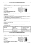
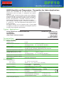
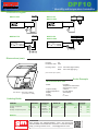
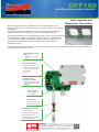
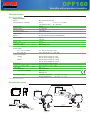
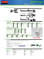
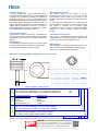
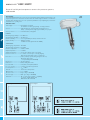
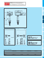
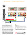
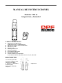
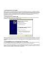
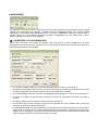
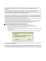
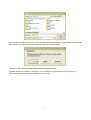
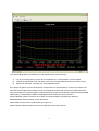
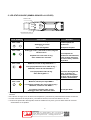
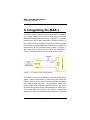
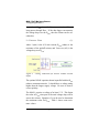
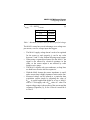
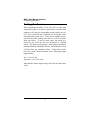
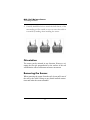
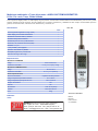
gm DPF sensors www.dpfsensors.com SENSORES DE HUMEDAD Y TEMPERATURA Mural interiores Exterior meteo Mural interiores Suelo agricultura www.guemisa.com - Mural/conducto interiores Aire comprimido Registrador interiores Control ambiental Tfno.: 91 764 21 00 - [email protected] DPF10 Humidity and temperature transmitter HVAC Humidity and Temperature Transmitter for Indoor Applications DPF10 room transmitters are the ideal solution for indoor applications such as HVAC in residential and official buildings. The very stylish, functional housing makes easy installation and fast exchange of the sensing unit for service purposes possible. The high quality DPF humidity sensor and state-ofthe-art microprocessor controlled electronics are the guarantee for best accuracy and a wide range of options. The standard humidity output of DPF10 transmitters is 4 - 20 mA or 0 - 10 V. The temperature output signal can be active or passive. All DPF10 versions can be equipped with a good legible LC display. For DPF10-FT versions the displayed values for humidity and temperature will alternate. Features T ypical A pplica tions building management for residential and office areas air conditioning switching cabinets climate control in hotels and museums excellent price / performance ratio easiest installation modern design long term stable optional display traceable calibration T ec hnical Data Da Measuring Quantities Relative Humidity Humidity sensor Analogue output 0...100 %r.H. Working range 1) Accuracy at 20°C (68°F) and UV=24VDC Temperature dependence at 60% RH HC103 0-10 V -1 mA < I L < 1mA 4-20 mA (two wires) RL < (UV-10)/0.02 < 500 Ohm 0...95 % RH ±2% RH (40...60% RH) ±3% RH (10...90% RH) Traceable to intern. standards, administrated by NIST, PTB, BEV... typical 0.06% RH /°C (0.03% RH / °F) Temperature (active output) Analogue output 0...50°C (32...122°F)2) Accuracy at 20°C (68°F) and UV=24VDC 0-10 V 4-20 mA (two wires) FT3: ±0.25°C (±0.45°F) -1 mA < IL < 1mA R L < (UV-10)/0.02 < 500 Ohm FT6: ±0.4°C (±0.72°F) Temperature (passive output) Type of T-Sensor please see ordering guide General Data Voltage supply (U V) for 0 - 10 V for 4 - 20 mA Current consumption Electrical connection Display CE compatibility according Temperature ranges 1) Please refer to the working range of the HC103 2) Other T-scaling refer to page 134 15 - 40 VDC or 24 VAC ±20% 28V DC > U V > 10 + 0.02 x RL (RL < 500 Ohm) for DC supply: typical 4 mA for AC supply: typical 15 mA eff screw terminals max. 1.5 mm2 (AWG 16) for DPF10-FTx version Humidity / Temperature alternating for DPF10-Fx and DPF10-FPx version Humidity EN 50081-1 FCC Part15 ClassB EN 50082-1 ICES-003 ClassB working temperature range: -5...55°C (23...131°F) working temperature with display: -5...55°C (23...131°F) storage temperature range: -25...60°C (-13...140°F) DPF10 Humidity and temperature transmitter Connection Diagram DPF10-FT3 DPF10-F3 DPF10-FP3 DPF10-FT6 DPF10-F6 DPF10-FP6 Dimensions (mm) Housing: PC Protection class: IP20 Housing colour: Cover: RAL 9003 (signal white) Back: RAL 7035 (light grey) (other colours upon request) Or der Example DPF10-FP6D-D04-T04 Model: Output humidity: Output temperature: Display: T-Unit: T-Scale: W x H x D = 85 x 100 x 26mm (3.3 x 3.9 x 1 inch) Humidity + Temperature Transmitter with passive T-output 4-20mA Pt 1000 DIN B with Display °C 0...50°C Ordering Guide MODEL OUTPUT T-SENSOR DISPLAY (only passive) humidity + temperature humidity humidity + temperature passive (FT) 0-10V (F) 4-20 mA (FP) (3) Pt 100 DIN A (6) Pt 100 DIN B T-SCALE T - UNIT (only for FT) (only for (D04)) (A) without display (B) with display (--) °C (D04) °F (--) (E01) (T04) -5...55 (T31) Pt 1000 DIN A (C) 0...40 (T55) Pt 1000 DIN B (D) other (Txx) DPF10- gm 0...50 GUEMISA Sta. Virgilia, 29 - 28033 Madrid - Tfno.: 91 764 21 00 Desde 1986 suministrando sensores e instrumentación. http://www.guemisa.com - [email protected] DPF160 Humidity and temperature transmitter HVAC Humidity and Temperature Transmitter Specially designed for HVAC, the DPF160 sensor by DPF Sensors is a costeffective, highly accurate and reliable solution for measuring relative air humidity and temperature. The enclosure minimizes installation costs and provides outstanding protection against contamination and condensation, thus ensuring flawless operation. The DPF160 employs the new humidity/temperature DPF sensor element HCT01 with excellent long term stability and resistance against pollutants. In combination with a long calibration experience, the DPF160 provides a measurement accuracy of ±2.5%RH and is available for wall or duct-mounted with current, voltage or Modbus RTU output. The configuration equipment allows user setup for the output scaling and for the interface parameters, as well as humidity and temperature adjustment of the sensor. Easily Adapted for the US Market » Knockout for ½” conduit fitting External mounting holes » Mounting with closed cover » Electronics protected against construction site pollution »Easy and fast mounting Electronics on the Underside of the PCB » Optimum protection against mechanical damage during installation Bayonet Screws » Open/closed with a ¼ rotation Cast Electronics »Mechanical protection »Condensation-resistant DPF Humidity sensor HCT01 »Long-term stability »Protected RH sensor surface »Protected solder pads »Tested according to automotive standard AEC-Q200 gm GUEMISA Sta. Virgilia, 29 - 28033 Madrid - Tfno.: 91 764 21 00 Desde 1986 suministrando sensores e instrumentación. http://www.guemisa.com - [email protected] DPF160 Humidity and temperature transmitter Technical data Measured values Relative Humidity Sensor Analog output 0...100% RH Digital output Working range Accuracy at 20°C Temperature dependency Temperature Sensor Analog output1) Digital output T-Accuracy at 20°C passive T-output DPF Sensor HCT01-00D 0-10 V -1 mA < IL < 1 mA oder 4-20 mA (two-wire) RL < 500 Ohm RS485 10...95% RH ±2.5% RH typ. ±0.03% RH/°C Pt1000 (tolerance class B, DIN EN 60751) 0-10 V 4-20 mA RS485 ±0.3°C see ordering code General Power supply for 0 - 10 V / RS485 for 4 - 20 mA Current consumption Analog 15 - 35V DC or 24V AC ±20% 10V + RL x 20 mA < UV < 35V DC with DC power supply typ. 5mA with AC power supply typ. 13mA with DC power supply typ. 15mA with AC power supply typ. 25mA Screw terminals, max. 1.5 mm Polycarbonate (UL listed) / IP65 M16 x 1.5 membrane filter EN61326-1 EN61326-2-3 Operating temperature: -15...60°C Storage temperature: -25...60°C eff Digital eff Connection Housing / protection class Cable gland Sensor protection Electromagnetic compatibility Temperature ranges 1) 2 ( 5...140°F) (-13...140°F) Output scaling see Ordering Guide Dimensions (mm) CONDUIT KNOCKOUT CABLE GLAND M16x1.5 Type B Type A DPF160 Humidity and temperature transmitter Connection diagram DPF160-HT3xxx 8 7 6 5 DPF160-HT6xxx DPF160-HTx3xx Ordering Guide Configuration ModEl ANAloG humidity + temperature (HT) 0-10V 4-20mA none 1) dIGITAl (3) (6) (x) RS485 none 1) PASSIVE T-SENSoR 2) (3) Pt 100 DIN A (x) Pt 1000 DIN A NTC 10k none (A) (C) (E) (x) HoUSING TYPE polycarbonate (P) wall mount duct mount fIl TER (A) (B) membrane filter (B) DPF160Interface parameter - analog output oUTPUT SCAlING temperature SCAlING (Tx) UNIT °C °F metric -20...80 (024) -32...122 (076) non-metric -40...60 (002) -40...140 (083) -10...50 (003) 0...180 (026) 0...50 (004) other Scalings see Datasheet „T-Scaling“ (M) (N) Interface parameter - digital output* PRoToCol modbus 1) BAUdRATE (1) 9600 19200 38400 PARITY SToPBITS (A) odd (B) even (C) no parity a combination of analog and digital version is not possible 2) (o) 1 stopbit (E) 2 stopbit (N) UNIT (1) metric (2) non-metric (M) (N) analogue version only DPF160-EXT Accessories Configuration equipment: The configuration equipment allows user setup for the output scaling and for the interface parameters, as well as humidity and temperature adjustment of the sensor. Position 1: - configuration adapter (incl. USB cable for PC) (HA011050) Position 2: - for DPF160 analog: cable for configuration adapter (HA011059) - for DPF160 digital: cable for configuration adapter (HA011055) HA011059 or HA011055 Position 3: - configuration software: free of charge; download: www.dpfsensors/dpf160.html (2013) Position 4 - optional: - power supply for DPF160 PC HA011050 (V03) Order example Analog output DPF160-HT6xAPAB-Tx001M Model: Analog output: Passive T-Sensor: Housing: Type: Filter: humidity + temperature transmitter 4-20mA Pt 100 DIN A polycarbonate wall mounting membrane filter Output scaling: Scaling: Unit: temperature -30...40° metric digital output DPF160-HTx3xPBB-1AE1N Model: Digital output: Housing: Type: Filter: humidity + temperature transmitter RS485 polycarbonat duct mounting membrane filter Protocol: Baudrate: Parity: Stopbits: Unit: Modbus 9600 even 1 non-metric V03 (optional) UTA Sensore Termoigrometrico con ventilazione naturale UTAV Sensore Termoigrometrico con ventilazione forzata Thermoigrometric sensor with fan Sensore realizzato in conformità agli standard WMO (World Meteorological Organization), disponibile anche nella versione con ventilazione forzata (cod..UTAV). Temperatura: Elemento sensibile a termoresistenza Pt100 1/3DIN con collegamento a quattro fili, uscita a Pt100 oppure segnale elettrico normalizzato in corrente o tensione (4÷20mA, 0÷2Vdc) o RS485/Modbus. Umidità relativa.: Sensore per la misura dell’umidità relativa dell’aria a basso consumo (<0,1W), costituito da un elemento a film sottile la cui capacità varia linearmente con l'umidità relativa dell'aria. Disponibile con uscite di segnale normalizzato in tensione o corrente (0÷1Vdc, 4÷20mA) o RS485/Modbus. Sensor manufactured according to standard WMO (World Meteorological Organization) and is also available in versions with forced ventilation (code. TAV). Temperature: RTD sensing element 1/3DIN Pt100, connection with a four-wire Pt100 output or electrical signal in current or voltage (4÷20mA, 0÷2Vdc) or RS485/Modbus. Relative Humidity: Sensor for air relative humidity measurement at low power (<0.1 W), made of a thin film that changes the capacity in linear mode with the air humidity. Available with different signal outputs, normalized voltage or current (0÷1Vdc, 4÷20mA) or Rs485/Modbus. Caratteristiche salienti / Highlighted specs • • • • • • Sensore di temperatura e umidità preciso ed affidabile / Accurated and reliable Air Humidity & Temperature Sensor Sistema di misura di tipo a termoresistenza Pt100 e capacitivo / Measure with high precision capacity and RTD Pt100 Struttura in robusto alluminio per climi caldi e freddi / Compact and light design in aluminium for hot and cold climates Conforme allo standard WMO / According to the WMO standards Disponibile con ventilazione forzata / Available with forced ventilation /According to norms Conforme alle norme Dati tecnici / Technical Data Campo di misura tipico temperatura [umidità] Temperature [humidity] typical range Risoluzione temperatura [umidità] Temperature [humidity] resolution Precisione temperatura [umidità] Temperature [humidity] accuracy Tempo di risposta temperatura [umidità] Temperature [humidity] response time Tipo di trasduttore Type of transducer Ventilazione Ventilation Segnale di uscita Signal out Condizioni operative Working conditions -40 ÷ +60°C, [0 ÷ 100%Rh] (-60+70°C available) 0.01°C, [0.05%] DIN 43760 1/3DIN (±0.1°C @ 0°C), [± 2% f.s.] < 8 s, [< 8sec (10÷80%RH)] Termoresistenza al Platino 1/3DIN / platinum resistance Pt100 1/3DIN (100Ω @ 0°C), [capacitivo / capacitive] Naturale / natural (cod. UTA) Forzata / Forced (cod. UTAV) N: 0÷1 Vdc(Rh) & Pt100 (T); A: 0÷1 Vdc(Rh) & 0÷2 Vdc (T) ; B: 4 ÷ 20mA (Rh) & 4 ÷ 20mA (T) ; C: 2 x RS485 /ModBus -50 ÷ +80°C (-60 ÷ +80°C available) Protezioni contro inversione di polarità e scariche atmosferiche Protections polarity reverse and transient Realizzato in lega di alluminio verniciato, viterie in inox Made of Alimentazione e consumo Power supply and consumption aluminium alloy, stainless steel screws Peso Weight 10÷30Vdc, (typ.<0.1W, max 2W@12Vdc mod. TAV) 680g NESA Srl si riserva di apportare eventuali modifiche al presente prodotto senza obbligo di preavviso / NESA Srl intend to do any modifications to this product without warning obligation Thermoigrometric sensor with natural ventilation Measurement principle Il sensore combinato per la misura della temperatura e dell’umidità dell’aria UTA è costituito da una termoresistenza al Platino Pt100 (100Ω@0°C), sensibile alle variazioni di temperatura secondo la curva di risposta riportata nelle norme DIN 43760 1/3DIN. Per l’umidità, l’elemento sensibile è una capacità elettrica di precisione che varia il suo valore in funzione dell’umidità. Tale variazione viene trasformata in un segnale elettrico normalizzato in corrente o in tensione o digitale RS485 Modbus, che varia in modo lineare e preciso con l’umidità relativa e la temperatura dell’aria. The combined sensor for the measure of the Air Temperature and Humidity UTA, is made of a Platinum termo-resistance Pt100 (100Ω @0°C), sensitive to the change of temperature according to the DIN 43760 norms 1/3DIN. For the umidity, the sensing element, is an high precision electrical capacity that varies as a function the humidity. This variance is converted into an electrical signal normalized in current or voltage or digital data RS485 / ModBus that is linear and follows exactly the relative humidity. Taratura del sensore Ogni strumento è tarato e verificato per comparazione con uno strumento campione primario certificato SIT/Accredia. A seguito della verifica, il sensore viene corredato di rapporto di taratura. Calibration of the sensor Every sensor is calibrated and verified comparing with SIT/Accredia primary certificated instrument. After the test the sensor is supplied with the calibration report. Manutenzione Con periodicità (1volta/trimestre) pulire con un panno umido gli schermi bianchi. Non usare detersivi o spugne abrasive. Una volta all’anno ricalibrare l’elemento sensibile. Maintenance Clear periodically (1 time/quarter) the white screens cover with a wet cloth. Don’t use detergents or abrasive sponges. Once a year, re-calibrate the sensing element. Dimensioni e collegamenti / Dimensions and connections 5 6 4 7 3 1 2 Pin 81 162mm mm 220mm Accessori Accessories Uscita Output Sensore Sensor 40mm UTA(V)-A UTA(V)-B UTA(V)-C UTA(V)-N 1 T Pin1 Pt100 2 T Out V+ T Out I+ T RS485 A T Pin1 Pt100 3 T Out V- T Out I- T RS485 B T Pin2 Pt100 4 Gnd Gnd 5 Vdc:10÷28V Vdc:10÷28V 12 Vdc Vdc:10÷28V RH% Out V+ RH% Out V- T Pin2 Pt100/Gnd Gnd 6 RH% Out V+ RH% Out I+ RH% RS485 A 7 RH% Out V- RH% Out I- RH% RS485 B Come ordinare / Order Form Sensore Temperatura e Umidità Relativa / Air Temperature & Humidity Sensor Sensore Temperatura e Umidità ventilato / Fan Air Temperature & Humidity Sensor Temperatura/Temperature 0÷2Vdc 4÷20mA Umidità/Humidity 0÷1Vdc 4÷20mA RS485 / Modbus RS485 / Modbus UTA UTAV A B C N 0÷1Vdc Naturale/natural: Pt100 CS05 – Cavo 5m sensore-datalogger / Cable 5m sensor-datalogger CS10 – Cavo 10m sensore-datalogger / Cable 10m sensor-datalogger CSxx – Cavo lunghezza xx* m / Cable xx* m length sensor – datalogger SS1 – Supporto sensori l=500mm / Sensors support l=500mm SS2 – Supporto sensori l=1500mm / Sensors support l=1500mm SS3 – Supporto sensori l=900mm / Sensors support l=900mm Esempio di codice d’ordine / example of order code 05 10 xx SS1 SS2 SS3 UTA per misure fuori standard specificare la lunghezza in metri / specify the length for no standard measures gm GUEMISA Sta. Virgilia, 29 - 28033 Madrid - Tfno.: 91 764 21 00 Desde 1986 suministrando sensores e instrumentación. http://www.guemisa.com - [email protected] A 10 SS2 NESA Srl si riserva di apportare eventuali modifiche al presente prodotto senza obbligo di preavviso / NESA Srl intend to do any modifications to this product without warning obligation Principio di misura HYGRASGARD ® ESFF ⁄ ESFTF Screw-in humidity and temperature sensors for pressure systems, calibrateable APPLICATION: Series ESFF ⁄ ESFTF humidity sensors are used for measuring the relative humidity and temperature of air in pressure systems and convert these measured values into standard signals of 0 -10 V or 4 ... 20 mA respectively. These humidity sensors are to be operated in pollutant-free non-precipitating air, mounted vertical with the sensor pointing down. ESFF ESFTF TECHNICAL DATA: Power supply: ............................... 24 V AC ⁄ DC for U variant 15 ... 36V DC for I variant, RL depending on working resistance Sensors: ....................................... digital humidity sensor with integrated temperature sensor, dew-proof, small hysteresis, high long-term stability ± 1 % per year Sensor protection: ...................... metal sinter filter, exchangeable HUMIDITY: Measuring range, humidity:........ 0 … 100 % r. H. Operating range, humidity: ......... 10 … 95 % r. H. Deviation, humidity: ..................... ± 3 % r. H. (40…60 %) at + 20 °C, otherwise ± 5 % r. H. Output, humidity: ......................... 0 - 10 V at U variant, 4...20 mA at I variant, (transmitter RL < 500 Ω) TEMPERATURE: Measuring range, temperature: ... 0 ....+ 50 °C Operating range, temperature: .... 0 ....+ 50 °C Deviation, temperature: ............. ± 0.5 K at + 20 °C Output temperature: .................. 4 ... 20 mA Ambient temperature: ................ storage - 25 …+ 60 °C, operation -5 …+ 55 °C Electrical connection: ................. 2- or 3-wire connection (see connecting diagram), 0.14 - 1.5 mm² via terminal screws on circuit board Enclosure:..................................... plastic, material polyamide, 30 % glass-globe-reinforced, with quick-locking screws, colour pure white (similar RAL 9010) Dimensions:.................................. 72 x 64 x 39.4 mm Cable union: .................................. M16, including strain relief Protective tube: ........................... metal, brass, nickel-plated, Ø 20 mm Process connection: ................... screwed socked with ½“ pipe thread Nominal pressure: ....................... p nenn < 20 bar Overload: ...................................... max. 5-fold nominal pressure Burst pressure: ........................... p max = 150 bar Protection class: ......................... III (according to EN 60 730) Protection type: ........................... IP 65 (according to EN 60529) Standards:.................................... CE conformity, electromagnetic compatibility according to EN 61 326 + A1 + A2, EMC directive 89 ⁄ 336 ⁄ EWG Circuit diagram ESFF - I Circuit diagram ESFTF - I Connecting diagram ESFF - I Connecting diagram ESFTF - I GUEMISA (Electrónica Guerra y Miró Guemisa S.L.) Sta. Virgilia, 29 - local - 28033 Madrid (Spain) Tlfno.: (034) 91 764 21 00 Fax.: (034) 91 764 21 32 Email.: [email protected] Web.: www.guemisa.com Dimensional drawing Circuit diagram ESFF ESFTF ESFF - U Circuit diagram ESFTF - U Connecting diagram ESFF - U Connecting diagram ESFTF - U HYGRASGARD ® ESFF and ESFTF: Type ⁄ WG1 Range humidity (relative) Range temperature Output humidity (relative) Output temperature ESFF - I 0 …100 % r. H. – 4 ... 20 mA – ESFF - U 0 …100 % r. H. – 0 -10 V – ESFTF - I 0 …100 % r. H. 0 …+ 50 °C 4 ... 20 mA 4 ... 20 mA ESFTF - U 0 …100 % r. H. 0 …+ 50 °C 0 -10 V 0 -10 V www.dfpsensors.com A TIC Ó M DO ADO N IO DI C N ACO E R AI ES N E AC ALM RES O S D I CA DOR E F I ID FICA M U H I DI M U H DE S HUMEDAD TEMPERATURA 0/100%HR SALIDA SALIDA 0/10V Pt100 %HR Longitud 126. Diámetro 20mm. Cable 3mts. Alimentación 12.. 30VDC. Temperatura de trabajo: -10/+60ºC Filtro capuchón: Malla metálica Precisión a 25ºC: ±4%RH (15.. 90%RH) Clip de plástico para montaje pared. Tiempo de saturación: 75seg. (25ºC - 50%RH) Tiempo de respuesta a 25ºC: 2seg. Dimensiones: ºC APLICACIÓN con REGULADOR DIS2 Flex DIS2 Flex DIS2 Flex C FN C FN T SE T SE %HR ºCz mA PASIVO 1 2 A1 Potenciómetro PTC / NTC SSR NO C NC C NO 3 4 5 6 7 8 9 10 11 12 Exc V 1 2 Relé1 Relé2 C1 A1 v/i Pt100 / Ni100 Potenciómetro PTC / NTC SSR NO C NC C NO 3 4 5 6 7 8 9 Termopar Relé2 C1 Pt100 / Ni100 24.. 230 VDC/AC Relé1 mA PASIVO Exc v/i Termopar 24.. 230 VDC/AC Exc 10 11 12 2 1 3 V Pt100 ROJO NEGRO ALIMENTACIÓN COMÚN AZUL MARRÓN BLANCO 2 1 Pt100 AMARILLO / VERDE SALIDA (0/10V) 3 ! MONTAJE Y CONEXIONES ELÉCTRICAS La humedad y la temperatura son unas unidades físicas fácilmente variables en un ambiente, especialmente si no está cerrado o sujeto a continuos y repentinos cambios de temperatura. Por estos motivos, el lugar y la posición en la que irá instalada y fijada la sonda de humedad y temperatura, debe ser el más adecuado posible, con el fin de obtener una correcta medida. Se aconseja instalar la sonda con el capuchón (sensor) direccionado hacia arriba, para protegerlo de eventuales salpicaduras de agua y evitar que esté en presencia de corrientes de aire. ADVERTENCIAS: - Proteger el sensor del agua (fría o caliente). - Los cambios bruscos de temperatura pueden afectar temporalmente la medición. En este caso puede producirse condensación del sensor interno, alterando momentáneamente la lectura de humedad. No obstante, este fenómeno no provoca ningún daño a la sonda. gm GUEMISA Sta. Virgilia, 29 - 28033 Madrid - Tfno.: 91 764 21 00 Desde 1986 suministrando sensores e instrumentación. http://www.guemisa.com - [email protected] MANUAL DE INSTRUCCIONES Medidor USB de temperatura y humedad REC ALM www.dfpsensors.com CARACTERÍSTICAS z z z z z z z z z Memoria para 32,000 lecturas (16000 temperatura y 16,000 humedad) Indicador de punto de rocío (condensación) Indicador de estado Interface USB Alarma personalizable Software de análisis Personalización de lecturas Pilas de larga duración Ciclos de medición personalizables: 2s, 5s, 10s, 30s, 1m, 5m, 10m, 30m, 1hr, 2hr, 3hr, 6hr, 12hr, 24hr DESCRIPCIÓN 1. Carcasa de protección 2. Conector USB para el PC 3. Botón de encendido 4. Sensores de humedad y 5. Alarmas LED 6. Luz verde (midiendo) 7. Soporte temperatura SIMBOLOGÍA DE LUCEZ LED Gr e e n LED REC ALM Re d /Ye l l ow LED GUÍA DE ESTADO LUCES LEDs REC REC REC ALM ALM ALM Indicador Ambas luces LED apagadas Datalogger no activo o Pilas descargadas Luz verde parpadea cada 10 seg. * Datalogger activo y tomando lecturas, ninguna alarma activa** Parpadeo luz verde cada 10 seg. Inicio mediciones retrasado Luz roja parpadea una sola vez cada 10 seg. * Midiendo, alarma de baja humedad *** Luz roja parpadea dos veces cada 10 seg. * Midiendo, alarma de alta humedad *** REC ALM Acción Puede empezar las mediciones Reemplace las pilas Para empezar las mediciones manualmente, pulse el botón hasta que las luces verde y amarilla parpadeen. Si se han descargado las pilas, se pararan las mediciones. Reemplace las pilas. No se perderán los datos almacenados. Luz roja parpadea cada 60 seg. Pilas descargadas**** Luz amarilla parpadea una sola vez cada 10 seg. * Midiendo, alarma para baja TEMP*** Luz amarilla parpadea dos veces cada 10 seg. * Midiendo, alarma de alta TEMP*** Descargue datos. Luz amarilla parpadea cada 60 seg. Datalogger lleno. No caben más datos. * Para alargar la vida de las pilas, las frecuencias inficadoras de las luces LED pueden ser modificadas desde el software. ** Para ahorrar energía, la luz de alarma de temperature y humedad se puede descativar desde el software. ***Cuando las alarmas de temperature y humedad se activan, las luces LED alternan su ciclo. ****Cuando las pilas están descargadas, todas las mediciones se paran, pero los datos hasta el momento almacenados no se pierden. ESPECIFICACIONES Humedad Relativa Temperatura Temperatura Punto de Rocío Intérvalos de lectura Temperatura de Trabajo Tipo pilas Duración pilas Dimensión/ Peso Rango Total Precisión (0 a 20 y de 80 a 100%) Precisión (20 a 40 y de 60 a 80%) Precisión (40 a 60%) Rango Total Precisión (-40 a -10 y de +40 a +70℃) Precisión(-10 a +40 ℃) Precisión (-40 a +14 y de 104 a 158℉) Precisión (+14 a +104 ℉) Rango Total 0 to 100% ±5.0% ±3.5% ±3.0% -40 a 70℃ ( -40 a 158℉) ±2℃ ±1℃ ±3.6℉ ±1.8℉ -40 a 70℃ ( -40 a 158℉) Precisión (25℃, 40 a ± 2.0 ℃ 100% HR) (±4.0℉) Frecuencia de medición desde 2 segundos hasta 24 horas. -35 a 80℃(-31 a 176℉) 3.6V litio(1/2AA)(SAFT LS14250, Tadiran TL-5101 o equivalente) 1 año (de media) dependiendo de la frecuencia de mediciones, temperatura ambiente y uso de alarmas y luces LED. 101x25x23mm (4x1x.9”)/ 172g (6oz) CAMBIO DE PILAS Usar sólo pilas de litio de 3.6V. Antes de reemplazar la pila, retirar el aparato del PC. Siga la explicación del diagrama a través de los siguientes pasos: 1. Con un objeto punzante (destornillador…), abra la carcasa en la dirección de la flecha. 2. Retire el Datalogger de la carcasa. 3. Reemplace/Inserte la nueva pila siguiendo los indicadores de polaridad que aparecen.. Las dos luces verde/amarilla) se iluminarán alternativamente como sistema de control. 4. Vuelva a introducer el Datalogger dentro de la carcasa. Ahora ya se puede volver a utilizar. AVISO: Dejar el aparato por tiempo prolongado conectado al PC reduce la vida de las pilas. 1 2 3 4 CUIDADO: Maneje las pilas de litio con cuidado y siguiendo las normas legales sobre su uso y reciclaje vigentes en su país. DPF07 DATALOGGER – GUÍA DEL SOFTWARE Datalogger Graph Software Help Version 2.0, August 07, 2007 En caso de necesitar información más detallada, consulte la guía incluida en el CD de instalación. ÍNDICE Instalación del Software….........................................................................2 Instalación del Driver USB........................................................................2 Funcionamiento del Datalogger Graph Software...................................2 Descripción de la Barra Menú .................................................................3 Simbología de la luz LED …………..........................................................7 1. INSTALACIÓN DEL SOFTWARE Instale el Windows PC Datalogger Software que viene adjunto instertando el disco en la unidad de CD-ROM su computadora. En caso de que el software de instalación no se ejecute automáticamente, haga doble click encima del archivo SETUP.EXE incluido en el CD de instalación. Siga las instrucciones de instalación que le aparecerá en la ventana que se abrirá. Antes de utilizar el software del Dtalogger conecte el aparto en la unidad USB de su computadora e instale el correspondiente driver tal y como se indica en el siguiente apartado. described in the next section. 2. INSTALACIÓN DEL DRIVER USB Inserte el Datalogger en algún Puerto USB disponible de su computadora. Si es la primera vez que conecta el Datalodder, le aparecerá la siguiente pantalla en su PC: Seleccione la primera opción de ‘recommended’ (asegúrese de que el CD de instalación está todavía en la unidad de CD-ROM) y siga las instrucciones que le irán apareciendo en las siguientes pantallas del proceso de instalación. Este proceso solo tendrá lugar la primera vez que se instale el driver. Una vez instalado, esta pantalla no volverá a aparecer. 3. FUNCIONAMIENTO DEL SOFTWARE DEL DATALOGGER Con el Datalogger conectado al PC, haga doble click en el icono del software del Datalogger para iniciar el programa. La pantalla principal del programa mostrará las opciones que se indican más abajo. Aviso: Cuando se inserta el Datalogger en el pureto USB, la batería del mismo se descarga a un ritmo superior al habitual. No tenga el aparato conectado al puerto USB duranto períodos prologados de tiempo con el fin de conservar durante más tiempo y mejor la batería del Datalogger. 2 4. BARRA MENÚ De izquierda a derecha, los iconos o símbolos de la barra menú representan las siguientes funciones: DATA DOWNLOAD (DESCARGA DE DATOS), LOGGER SETUP (CONFIGURACIÓN), FILE OPEN (ABRIR ARCHIVO), FILE SAVE-AS (GUARDAR ARCHIVO), FILE PRINT (IMPRIMIR), VIEW ALL (VER TODOS), y ZOOM. Además, en la parte superior aparecen las opciones desplegables de FILE, VIEW, LINK, y HELP, también explicadas en los próximos parágrafos. ① LOGGER SETUP (CONFIGURACIÓN) Pulse sobre el segundo icono desde la izquierda o bien seleccione la opción LOGGER SET del menú desplegable que encontrarán en la opción de LINK. La pantalla de configuración se le aparecerá. Debajo de la ilustración le explicamos cada apartado: El campo de CURRENT TIME se sincroniza automáticamente con la fecha y hora de su PC. El MANUAL e INSTANT botones de selección le permiten iniciar las mediciones de temperature de forma instantánea (INSTANT) al salir del programa o bien manual (MANUAL) más tarde. El LOGGER NAME permite dar nombre a cada Datalogger para identificarlo en caso de que tuviera varios. El campo de SAMPLE POINTS permite confirgurar el número de mediciones que desea que realice el aparato. El SAMPLE RATE permite configurar la frecuencia de las mediciones. El LED Flash Cycle permite configurar la frecuencia de parpadeo de la luz indicadora LED. Cuanto más especiado en el tiempo más ahorro de batería. Los ALARM SETTINGS del menu de SETUP le permite confugurar los límites de alerta por enciama HIGH o debajo LOW en function de unos valores predeterminados de temperature y humedad que usted desee. Cuando éstos se sobrepasen, el aparato le avisará encendiendo la luz LED su usted lo desea. Para ello debe activarlo desde la opción de “LED’s flash for high an low alarm”. 3 Para guardar la configuración personalizada, pulse sobre el botón de SETUP. Pulse en el botón de DEFAULT para reestablecer los parámetros que por defecto vienen de fábrica. Pulse CANCEL para cancelar la configuración. Aviso: Toda la información almacenada en el Datalogger se eliminará una vez se haya terminado un nuevo proceso de configuración. Guarde los datos antes de realizar una nueva configuración del aparato. Asimismo, asegúrese antes de iniciar un nuevo proceso de medición que la batería se encuentra en buen estado para que dure hasta el final del período de medición indicado por usted. Si se seleccionó la opción INSTANT en el menu de configuración SETUP, el Datalogger inidicará el proceso de medición una vez se haya pulsado el botón de SETUP. Si se seleccionó la opción de MANUAL, el Datalogger empezará las mediciones una vez se haya pulsado manualmente el botón amarillo del aparato durante aprox. 3 segundos o hasta que las dos luces del aparato se enciendan a la vez. El almacenamiento de las mediciones continuarán con la frecuencia indicada por usted hasta alcanzar el numéro de mediciones (sample points) que especificó en la pantalla de configuración. La luz LED verde parpadea cada vez que se realize una medición y las luces amarilla o roja se encienden en señal de alarma cuando se ha excedido (por encima o por debajo) la temperatura del rango por usted preestablecido. Para más información, vea el apartado de Simbología de la luz LED. ② DATA DOWNLOAD (DESCARGA DE DATOS) Siga los siguientes pasos para pasar los datos almacenados desde su Datalogger a su PC: A. Conecte el Datalogger al mismo puerto USB que utilize cuando lo instaló por primera vez. B. Abra el programa del Datalogger si todavía no está abierto. C. Pulse sobre el primer icono empezando desde la izquiera o seleccione la opción Data Download desde el desplegable LINK. D. Le aparecerá la siguiente ventana. Pulse el botón DOWNLOAD para iniciar el proceso de descarga. Si los datos de las mediciones han sido descargados correctamente, las ventanas de VIEW y la de SAVE (ambas se muestran más abajo) aparecerán. En la ventana de SAVE, indique el nombre del archivo y donde desea guardar los datos en su PC. Más adelante podrá utilizar la opción de SAVE-AS y guardar también los datos en diferentes formatos como Excel, Texto, etc.. si no se dice nada, los datos serán guardados bajo la extensión de archivo .rec utilizada sólo por este programa. 4 En la ventana de VIEW (debajo) pulse el botón de VIEW para visualizar los datos gráficamente. Si no hay datos almacenados, el programa se lo indicará apareciéndole una ventana de alerta. Cuando se pulsa el botón de VIEW, aparece la ventana gráfica de datos. El gráfico de datos se muestra en dos ejes x-y con la Fecha/Hora representada en el eje horizontal y la Temperatura/Límites de Alarma representados en el eje de la y: 5 Para acercar/alejar datos y visualizalos con más detalle existen varias opciones: 1) Con el mouse haga click o arrastre la zona alrededor de un area de datos y así la ampliará. 2) También puede ampliar la zona de datos con la icono correspondiente que tiene en la barra menú. 3) Seleccione VIEW ALL o ZOOM OUT del desplegable VIEW. En el ejmplo de gráfico que se muestra arriba, la temperature es representada por la línea roja continua. Las trazas de linea roja discontinua reflejan zonas de temperatura donde se han superado los límites de alarma. Para personalizar la ventana del gráfico, puede seleccionar las opciones de SHOW TRACES, BACKGROUND, GRID LINES, y MASK POINTS desde el desplegable VIEW. Éstas opciones le permitirán: SHOW TRACES: Permite al usuario ver los datos con lineas trazadas (Temperatura & Alarmas). BACKGROUND: Permite cambiar el color del entorno. GRID LINES: Permite incluir o quitar líneas de los ejes x e y. MASK POINTS: Permite resaltar los puntos de mediciones de la línea continua. 6 ③ FILE OPEN, FILE SAVE-AS (ABRIR ARCHIVO, GUARDAR COMO..) Para pasar de los datos almacanados en el formato de este programa (.rec) a otros formatos,pulse sobre el icono de SAVE AS (el cuarto desde la derecha o bien seleccione la opción SAVE AS desde el desplegable FILE. El archivo puede ser guardado en los siguientes formatos: TEXT FILE (.txt) - Texto EXCEL FILE (.xls) - Excel BITMAP FILE (.bmp) – Bitmap (archivo de imágen) Para abrir un archivo guardado y verlo en el gráfico de datos, haga clic sobre el icono de FILE OPEN (tercero desde la izquierda) o bien seleccione la opción FILE OPEN desde el desplegable FILE. Seleccione el archivo .rec que desee abrir. ④ FILE PRINT (IMPRIMIR DATOS) Para imprimir los datos, pulse sobre el icono PRINT desde el desplegable FILE. El gráfico puede ser imprimido en color utilizando impresora de color. Aviso : El Datalogger mantiene almacenados los datos en su interior hasta que se inicia una nueva sesión de mediciones. Cuando se inicia una nueva session de mediciones, el Datalogger borra los datos almacenados hasta el momento en el aparato. Asegúrese de haber guardado los datos antes de iniciar una nueva session de mediciones. 7 5. LED STATUS GUIDE (SIMBOLOGÍA DE LA LUZ LED) Gr e e n LED REC ALM Re d /Ye l l ow LED LED Status Indicador Acción Ambas luces LED apagadas REC ALM REC ALM Datalogger no activo o Pilas descargadas Luz verde parpadea cada 10 seg. * Datalogger activo y tomando lecturas, ninguna alarma activa** Parpadeo luz verde cada 10 seg. Inicio mediciones retrasado REC ALM Puede empezar las mediciones Reemplace las pilas Para empezar las mediciones manualmente, pulse el botón hasta que las luces verde y amarilla parpadeen. Luz roja parpadea una sola vez cada 10 seg. * Midiendo, alarma de baja humedad *** Luz roja parpadea dos veces cada 10 seg. * Midiendo, alarma de alta humedad *** Luz roja parpadea cada 60 seg. Pilas descargadas**** REC ALM Si se han descargado las pilas, se pararan las mediciones. Reemplace las pilas. No se perderán los datos almacenados. Luz amarilla parpadea una sola vez cada 10 seg. * Midiendo, alarma para baja TEMP*** Luz amarilla parpadea dos veces cada 10 seg. * Midiendo, alarma de alta TEMP*** Luz amarilla parpadea cada 60 seg. Descargue datos. Datalogger lleno. No caben más datos. * Para alargar la vida de las pilas, las frecuencias inficadoras de las luces LED pueden ser modificadas desde el software. ** Para ahorrar energía, la luz de alarma de temperature y humedad se puede descativar desde el software. ***Cuando las alarmas de temperature y humedad se activan, las luces LED alternan su ciclo. ****Cuando las pilas están descargadas, todas las mediciones se paran, pero los datos hasta el momento almacenados no se pierden. gm 8 GUEMISA Sta. Virgilia, 29 - 28033 Madrid - Tfno.: 91 764 21 00 Desde 1986 suministrando sensores e instrumentación. http://www.guemisa.com - [email protected] MAS-1 4-20 mA Soil Moisture Sensor User Manual Version 4 gm GUEMISA Sta. Virgilia, 29 - 28033 Madrid - Tfno.: 91 764 21 00 Desde 1986 suministrando sensores e instrumentación. http://www.guemisa.com - [email protected] MAS-1 Soil Moisture Sensor Contents 1. Introduction . . . . . . . . . . . . . . . . . . . . 1 Customer Support. . . . . . . . . . . . . . . . . . . . . . 1 Warranty . . . . . . . . . . . . . . . . . . . . . . . . . . . . . 3 Seller’s Liability . . . . . . . . . . . . . . . . . . . . . . . 3 2. About the MAS-1 . . . . . . . . . . . . . . . 4 3. Integrating the MAS-1 . . . . . . . . . . . . 5 Wiring . . . . . . . . . . . . . . . . . . . . . . . . . . . . . . . 6 Conventional (PLC) . . . . . . . . . . . . . . . . . . . 6 Non-Conventional . . . . . . . . . . . . . . . . . . . . 6 Testing the Sensor . . . . . . . . . . . . . . . . . . . . . 9 4. Installing the MAS-1 . . . . . . . . . . . . 10 Procedure . . . . . . . . . . . . . . . . . . . . . . . . . . . 10 Orientation . . . . . . . . . . . . . . . . . . . . . . . . . . 11 Removing the Sensor . . . . . . . . . . . . . . . . . . 11 5. Calibration . . . . . . . . . . . . . . . . . . . . . 12 Mineral Soils . . . . . . . . . . . . . . . . . . . . . . . . . 12 Potting Soil/Peat. . . . . . . . . . . . . . . . . . . . . . 13 Rock Wool . . . . . . . . . . . . . . . . . . . . . . . . . . 13 6. Troubleshooting . . . . . . . . . . . . . . . . 14 Declaration of Conformity. . . . . . . . . . . 15 Index. . . . . . . . . . . . . . . . . . . . . . . . . . . . 16 i MAS-1 Soil Moisture Sensor 1. Introduction 1. Introduction Thank you for choosing the MAS-1 4-20 mA Soil Moisture Sensor. These innovative sensors will enable you to monitor soil moisture accurately and affordably with a standard 2wire, 4-20 mA analog interface for use with many data acquisition and control systems. The MAS-1 cannot be used with the standard Decagon data loggers. Customer Support If you ever need assistance with your MAS-1, or if you just have questions or feedback, there are several ways to contact us. Customer service representatives are available to speak with you Monday thru Friday, between 7am and 5pm Pacific time. NOTE: If you purchased your MAS-1 through a distributor, please contact them for assistance. E-mail: [email protected] or [email protected] Phone: 1-509-332-5600 Fax: 1-509-332-5158 If contacting us by email or fax, please include as part of your message your instrument’s serial number, your name, address, phone, fax number and a description of your problem. 1 MAS-1 Soil Moisture Sensor 1. Introduction Specifications Electrical Interface: Standard 4-20 mA, 2-wire analog transmitter Supply voltage: 12-32 VDC continuous Output current: 4-20 mA Overvoltage protection: Yes Reverse polarity protection: Yes Settling time: 4 seconds Wiring: Red wire: (+) supply Black wire: (-) output Shield: Not connected Measurement Type: Volumetric water content (VWC) Range: 0-100% VWC typical Resolution: Depends on current measurement (data acquisition) device Accuracy: ± 6 % VWC with generic calibration for supported growing media up to 65% VWC, above which accuracy lessens. Increased accuracy can be achieved with a medium specific calibration. For more information on how to perform your own media specific calibration, or to have Decagon’s calibration service perform one for you, visit us online at http://www.decagon.com. Output: 4-20 mA current proportional to VWC Sensor measurement interval: 1 second Operating Environment Temperature: -40 to 50 °C Physical Properties Dimensions: 8.9 cm x 1.8 cm x 0.7 cm Cable: 2 m or 5 m (standard), 3 wire (22 AWG tinned Red and Black wires, 24 AWG tinned bare wire); (Custom cable length available upon request) 2 MAS-1 Soil Moisture Sensor 1. Introduction Warranty The MAS-1 has a one year warranty on parts and labor. It is activated upon the arrival of the instrument at your location. Seller’s Liability Seller warrants new equipment of its own manufacture against defective workmanship and materials for a period of one year from date of receipt of equipment (the results of ordinary wear and tear, neglect, misuse, accident and excessive deterioration due to corrosion from any cause are not to be considered a defect); but Seller’s liability for defective parts shall in no event exceed the furnishing of replacement parts F.O.B. the factory where originally manufactured. Material and equipment covered hereby which is not manufactured by Seller shall be covered only by the warranty of its manufacturer. Seller shall not be liable to Buyer for loss, damage or injuries to persons (including death), or to property or things of whatsoever kind (including, but not without limitation, loss of anticipated profits), occasioned by or arising out of the installation, operation, use, misuse, nonuse, repair, or replacement of said material and equipment, or out of the use of any method or process for which the same may be employed. The use of this equipment constitutes Buyer’s acceptance of the terms set forth in this warranty. There are no understandings, representations, or warranties of any kind, express, implied, statutory or otherwise (including, but without limitation, the implied warranties of merchantability and fitness for a particular purpose), not expressly set forth herein. 3 MAS-1 Soil Moisture Sensor 2. About the MAS-1 2. About the MAS-1 The MAS-1 measures the dielectric constant of the soil in order to find its volumetric water content. Since the dielectric constant of water is much higher than that of air or soil minerals, the dielectric constant of the soil is a sensitive measure of water content. The MAS-1 supplies a 70 MHz oscillating wave to the sensor prongs that induces an electromagnetic field in the medium (soil) surrounding the sensor. The charging and discharging of the sensor is controlled by the dielectric of the surrounding soil. A microprocessor on the MAS-1 measures the charging of the sensor, and therefore the dielectric constant of the soil which is related to the water content of the soil. The microprocessor makes a dielectric measurement and updates the transmitted current once per second. The transmitted 4-20 mA current can be converted to the water content of the soil using a simple calibration function. The MAS-1 was designed to be used with standard 4-20 mA controllers and monitoring systems. It cannot be used with Decagon logging systems. For more information about using Decagon logging systems please contact Decagon’s customer support representatives. 4 MAS-1 Soil Moisture Sensor 3. Integrating the MAS-1 3. Integrating the MAS-1 A 4-20mA system generally consists of a sensor, a transmitter, a power supply, and a device to read the current being transmitted through the current loop. The MAS-1 is an integrated sensor and 4-20mA transmitter. When the MAS-1 is powered by the Power Supply, it transmits a current though the loop that is proportional to the soil dielectric permittivity and therefore the soil volumetric water content. In Figure 1, the current loop is shown by the dotted line labeled I=420mA. The arrows indicate the direction of the current. Figure 1 - 4-20mA current loop diagram The MAS-1 uses a microcontroller to regulate the interval at which it takes measurements. It takes one second from the time it is powered up to take its first measurement and transmit current though the loop. The trasnmitted current will reach a stable value within four seconds of power up. After the initial four second startup, measurements are taken every one second, while the current in the loop is continuously maintained. Since the measurement intervals are controlled 5 MAS-1 Soil Moisture Sensor 3. Integrating the MAS-1 by the MAS-1 itself, there is no need to pulse the excitation voltage. A constant supply voltage should be applied in order for the MAS-1 to function as it is designed. Wiring Conventional (PLC) A Programmable Logic Controller (PLC) is typically used to read the current transmitted through the MAS-1. The red wire (see Figure 2) of the MAS-1 is connected to a voltage output terminal that is able to supply 12-32 VDC. The black wire is connected to an input terminal that is capable of accepting a current input ranging from 4 mA to 20 mA. For the MAS-1 to function properly, the voltage drop from the red to the black lead must be 12 V or greater. Figure 2 - Typical wiring connection Non-Conventional When using a device, such as a data logger, that does not have an input capable of measuring current, a pickoff resistor can be used as shown in Figure 3. Assuming that the Single Ended Input has an input impedance, or resistance, much 6 MAS-1 Soil Moisture Sensor 3. Integrating the MAS-1 larger that of RVolt, then all of the current in the 4-20 mA loop passes through RVolt. If the data logger can measure the voltage drop over the RVolt, then the current can be calculated as I = Vmeasured / RVolt (1) where I (mA) is the 4-20 mA current, RVolt (ohms) is the resistance of the pickoff resistor, and Vmeasured (mV) is the voltage drop over RVolt. Figure 3 - Wiring connection for devices without current inputs The optional 100uF capacitor shown in parallel with the RVolt reduces measurement noise. It should have a voltage rating higher than the largest supply voltage. Be sure to observe correct polarity. The MAS-1 requires a voltage of at least 12 V. This limits the value of RVolt since part of the total voltage drop will be across the resistor. Equation (2) can be used to determine the maximum value for RVolt. Table 1 shows some resistance values. 7 MAS-1 Soil Moisture Sensor 3. Integrating the MAS-1 VSupply - 12 = 0.02 RVolt Max (2) Supply Voltage Load 13 V 50 ohms 24 V 600 ohms 32 V 1000 ohms Table 1 – Maximum resistance values for RVolt at specified voltages The MAS-1 sensor has several advantages over voltage-output sensors, even for voltage-input data loggers. • • • • • The MAS-1 supply voltage doesn’t need to be regulated for the sensor to work properly; it can be any value between 12 and 32 volts, without affecting sensor output. When using a current-based sensor like the MAS-1, the signal is not affected by electrical resistance in the cable, so the sensor output is not affected by cable length or wire gauge. The MAS-1 requires only two conductors, so long lines are both lower in noise and less expensive. With the MAS-1sensor the source impedance is small, and a current loop is highly immune to noise on the line. Measured voltage can be tailored to a particular data acquisition system simply by adjusting the value of RVolt. A typical application might be to use a MAS-1 with a 12 volt supply and a RVolt value of 1 ohm. The output voltage range is the product of the current and the resistance (Equation (1)), so for 4-20 mA it would be 4 to 20 mV. 8 MAS-1 Soil Moisture Sensor 3. Integrating the MAS-1 Testing the Sensor After integrating the MAS-1 into your PLC or other data acquisition system, it is always a good idea to test the sensor output to verify that it is functioning correctly with your system. Two convenient test conditions are having the sensor surrounded by air and water. To test in air, suspend the sensor from the cable, making sure that it is at least 6 inches from any object. To test in water, place the sensor in a bucket of tap water (do not use de-ionized or distilled water). The entire sensor (prongs + black plastic electronics portion) should be immersed in water, and should be at least 2 inches from any container surface. Under these conditions, the sensor should transmit in the following ranges (approximate): Air: 3.4 to 4.7 mA Tap water: 18.1 to 22.4 mA Note that the sensor output can go above 20 mA and below 4 mA. 9 MAS-1 Soil Moisture Sensor 4. Installing the MAS-1 4. Installing the MAS-1 When selecting a site for installation, it is important to understand that the soil adjacent to the sensor surface has the strongest influence on the sensor reading and that the sensor measures the volumetric water content. Therefore any air gaps or excessive soil compaction around the sensor can profoundly influence the readings. Also, do not install the sensors adjacent to large metal objects such as metal poles or stakes. This can attenuate the sensor's electromagnetic field and adversely affect sensor readings. Because the MAS-1 has gaps between its prongs, it is also important to consider the size of the media you are inserting the sensor into. It is possible to get sticks, bark, roots or other material stuck between the sensor prongs, which will adversely affect readings. Finally, be careful when inserting the sensors into dense soil, as the prongs will break if excessive sideways force is used when pushing them in. Procedure 1. The MAS-1 sensor was designed for easy installation into the soil. After digging a hole to the desired depth, push the prongs on the sensor into undisturbed soil at the bottom of the hole or into the sidewall of the hole. Make sure that the prongs are buried completely up to the black overmolding. The sensor may be difficult to insert into extremely compact or dry soil. If you have difficulty inserting the sensor, try loosening the soil somewhat or wetting the soil. Never pound it in! 10 MAS-1 Soil Moisture Sensor 4. Installing the MAS-1 2. Carefully backfill the hole to match the bulk density of the surrounding soil. Be careful to not over stress the cable or overmold by bending when installing the sensor. Orientation The sensor can be oriented in any direction. However, orienting the flat side perpendicular to the surface of the soil will minimize effects on downward water movement. Removing the Sensor When removing the sensor from the soil, do not pull it out of the soil by the cable! Doing so may break internal connections and make the sensor unusable. 11 MAS-1 Soil Moisture Sensor 5. Calibration 5. Calibration The current transmitted by the MAS-1 is proportional to the dielectric permittivity of the medium surrounding the sensor, and therefore its volumetric water content (VWC) of the medium. The VWC is calculated by applying a calibration equation to the current transmitted by the MAS-1. The following are generic calibration equations for common growth media. Applying these equations will generally result in accuracy of ± 6% VWC as long as the electrical conductivity of the medium is less than 8 dS/m. If you wish to use the MAS-1 in a medium that isn't listed below, if you need better than ± 6% accuracy, or if you are working in a high salinity material, then you should develop a custom calibration for your particular medium. See www.decagon.com for step-by-step instructions on developing a custom calibration. Decagon can also develop a custom calibration for your medium; contact Decagon for more details on the calibration service. Mineral Soils A single calibration equation will generally result in good accuracy for all mineral soil types with electrical conductivity < 8 dS/m. VWC is given by: VWC = 0.00328 * mA2 - 0.0244 * mA - 0.00565 If your data acquisition system isn’t capable of higher order mathematical operations, the mineral soil calibration can be 12 MAS-1 Soil Moisture Sensor 5. Calibration approximated by the following linear model. This will result in slightly worse accuracy at low VWC, with errors becoming large above 35% VWC. VWC= 0.0479 * mA - 0.391 Potting Soil/Peat The following equation can be used to convert MAS-1 transmitted current into VWC in potting soil and peat potting mixes. Please note that different potting soil types are quite variable, so this calibration equation may not result in good accuracy in your particular mix (although precision should still be good). We recommend a custom calibration for best accuracy when using the MAS-1 in potting soils. VWC = 0.00531 *e(0.29*mA) Rock Wool The MAS-1 was calibrated in Groden Expert™ rockwool at several electrical conductivities. VWC can be calculated as: VWC = 0.00446 * mA2 - 0.0359 * mA + 0.0741 13 MAS-1 Soil Moisture Sensor 6. Troubleshooting 6. Troubleshooting If you encounter problems with the MAS-1, they will usually be caused by one of two situations • If the MAS-1 readings in air and/or water are outside the ranges given in the Testing the Sensor section, then there is likely a problem with the connection to the PLC or other data acquisition system. Check the wiring and check to make sure that the supply voltage is in the specified range. • If the MAS-1 is reading a negative value for VWC while it is inserted into the soil, make sure that you have good sensor-to-soil contact. When inserted, the MAS-1 should be completely covered up past the black overmolding. Removing and re-installing the full length of the sensor with good sensor-to-soil contact should remedy this problem. If problems persist, contact Decagon for assistance. 14 Medidores ambientales » Termo higrometro » HIBOK 302 TERMOHIGRÓMETRO H. Rel., Pto. rocio, Temp., Búlbo húmedo Termo higrómetro digital portátil, con doble display de gran precisión. Puede medir humedad relativa, humedad absoluta, punto de rocío y bulbo húmedo, además de otras funciones. De gran utilidad por su tamaño, prestaciones y fiabilidad. De fácil manejo. Recomendable para uso general, aire acondicionado, cámaras de frío, alimentación y conservas, etc. ● Características: Cód. 435 Termo higrómetro digital de 3 ½ dig. (1999) Doble display para medidas simultaneas Medidas de humedad relativa y absoluta Medida de temperatura ambiente Medida del punto de rocío y bulbo húmedo Modo max, min, retención de lectura (Hold) Medida en º C y º F Luz en pantalla y auto apagado Aparición de símbolos en pantalla Manejable, ergonómico y fácil de usar Selección de rango: auto rango ● H302 • • • • • • • • • • • Especificaciones: Medidas de HUMEDAD Rango Resolución / Precisión Medidas de TEMPERATURA Rango Resolución / Precisión Otras especificaciones 0.0% a 100% H.R. 0.1 % y 1% / ±(3%) + 2 dig. -20º C a 60º C 0.1º C y º C / ±(0.5º C) Sensor de humedad Rango temperatura para bulbo húmedo Rango temperatura para punto de rocío Tiempo de muestreo Normas Alimentación Tamaño Peso Capacitivo de alta precisión 0º C a 80º C -30º C a 100º C 15s. CE 1 bat. de 9V (6F22) 220 x 63 x 28 mm 400g. Accesorios Incluidos: ● Fabricante: HIBOK ● GUEMISA (Electrónica Guerra y Miró Guemisa S.L.) Sta. Virgilia, 29 - local - 28033 Madrid (Spain) Tlfno.: (034) 91 764 21 00 Fax.: (034) 91 764 21 32 Email.: [email protected] Web.: www.guemisa.com Batería Estuche Instrucciones en castellano


![取扱説明書[SR-HC3/HD3] (18.15 MB/PDF)](http://vs1.manualzilla.com/store/data/006529571_2-3b48fa831230383b69c16cb739499147-150x150.png)