1
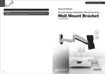
MANUAL DE INSTRUCCIONES
SOPORTE PARA TV LED/LCD (32” – 55”)
WM-5294
ESTIMADO CLIENTE
Con el fin de que obtenga el mayor desempeño de su producto, por favor lea este manual de
instrucciones cuidadosamente antes de comenzar a utilizarlo, y guárdelo para su futura referencia.
Si necesita soporte adicional, no dude en escribir a: [email protected]
ÍNDICE
INSTRUCCIONES DE SEGURIDAD ......................................................................................................... 1 CONTENIDO .............................................................................................................................................. 2 ENSAMBLAJE DE LA PLACA DE PARED .............................................................................................. 3 MONTAJE EN PARED DE LADRILLO O CONCRETO............................................................................ 3 ENSAMBLAR LOS SOPORTES ADAPTADORES .................................................................................. 4 INSTALACIÓN DE LOS SOPORTES ADAPTADORES........................................................................... 4 COLGAR EL TELEVISOR CON LOS SOPORTES EN LA PARED ......................................................... 5 MANTENIMIENTO ..................................................................................................................................... 5 LÍNEAS DE SERVICIO AL CLIENTE PREMIER
Venezuela:
Panamá:
Sitio Web:
E-mail:
0800 – ELECTRIC (353-2874)
300-5185
www.premiermundo.com
[email protected]
NOTA
Nos reservamos el derecho de modificar las especificaciones, características y/u operación de este
producto sin previo aviso, con el fin de continuar las mejoras y desarrollo del mismo.
INSTRUCCIONES DE SEGURIDAD
•
•
•
•
•
•
•
•
•
Lea primero todas las instrucciones antes debe comenzar la instalación. Si tiene alguna pregunta
contacte a su distribuidor local.
El soporte debe ser instalado y utilizado únicamente como se especifica en este manual. Una
instalación inadecuada puede ocasionar daños y lesiones.
El producto debe ser instalado por una persona con buenas habilidades mecánicas y con algo de
experiencia básica en construcción quien comprenda este manual.
Asegúrese de que la superficie donde coloque el soporte tiene la capacidad para soportar el peso
combinado del producto y los elementos que allí cuelgue.
No exceda la capacidad máxima de carga.
Instale este producto únicamente en pared de concreto.
Utilice la ayuda de un asistente o equipo de levantamiento mecánico para colocar el equipo de
forma segura en posición.
Apriete los tornillos con firmeza, pero no demasiado. Excederse puede dañar los elementos y
reduce la capacidad de soporte.
El producto está diseñado para uso en interiores. No lo utilice en exteriores.
P-1
CONTENIDO
Asegúrese de que todas las partes están completas de acuerdo con esta lista de verificación. En caso
de que algo haga falta o alguna parte esté defectuosa, comuníquese con su distribuidor local para
solicitar un reemplazo. El peso máximo de soporte es de 50 kg.
Placa de pared (x2)
A
Soporte adaptador (x2)
B
Conector (x2)
Paquete M
Arandela (x4)
M-D
Paquete W
ST6.3x55 Tornillo Tirafondo (x4)
W-A
Chazo de Concreto (x4)
W-B
HERRAMIENTAS REQUERIDAS
• Destornillador de estrella (200 mm de longitud excluyendo el mango)
• Toma y llave M6
• Taladro eléctrico y broca para concreto de 10 mm
• Marcador
• Martillo
P-2
Arandela 6.5x16 (x4)
W-C
ENSAMBLAJE DE LA PLACA DE PARED
MONTAJE EN PARED DE LADRILLO O CONCRETO
IMPORTANTE
• Al instalar soportes de pared en bloques de hormigón verifique que tiene un espacio mínimo de
35mm del grosor del concreto en el orificio que va a utilizar para los chazos de concreto. ¡No taladre
en las juntas de mortero! Asegúrese de hacer el montaje en una parte sólida del bloque,
generalmente al menos 25mm del lado del bloque. Se sugiere utilizar el taladro eléctrico en la
configuración baja en lugar de en la opción de percutor para evitar romper la parte posterior del
orificio al ingresar a un vacío o cavidad.
• El instalador debe verificar que la superficie soporte el peso combinado del soporte y los elementos
que vaya a colgar.
•
•
Utilice la placa de pared como una plantilla para marcar las ubicaciones de los cuatro orificios en la
pared. Dos en las ranuras de la parte superior y dos en la parte inferior, como se muestra en la
figura 1.1.
Pre-taladre estos orificios con un broca de 10mm llegando a una profundidad de al menos 60mm.
Inserte un chazo de concreto (W-B) en cada uno de los orificios. Coloque la placa de pared
utilizando los cuatro tornillos tirafondo (W-A) y las cuatro arandelas M6 (W-C), como se muestra en
la figura 1.2.
P-3
ENSAMBLAR LOS SOPORTES ADAPTADORES
Coloque los tornillos de seguridad en los soportes adaptadores como se muestra en la figura 2.1
INSTALACIÓN DE LOS SOPORTES ADAPTADORES
•
•
•
Para evitar que la pantalla se raye, coloque una prenda sobre una superficie plana que soporte el
peso del televisor.
Coloque el televisor boca abajo. Coloque los soportes adaptadores en la parte posterior del
televisor, alinee los orificios y centre los soportes en la parte posterior del televisor, como se
muestra en la figura 3.1.
Coloque los soportes adaptadores en la parte posterior del televisor utilizando una combinación
adecuada de tornillos y arandelas, como se muestra en la figura 3.2.
Los tornillos deben dar al menos tres vueltas completas en los orificios de montaje. No los apriete
P-4
demasiado para evitar dañarlos.
COLGAR EL TELEVISOR CON LOS SOPORTES EN LA PARED
Importante: Este paso del montaje se debe hacer con 2 personas.
• Cuelgue los soportes en la parte superior de la placa de pared como se muestra en la figura 4.1.
• Apriete los tornillos de seguridad en los soportes usando un destornillador adecuado. Asegúrese de
que el televisor quede bien enganchado y los tornillos de seguridad del cierre queden firmes antes
de soltar el televisor.
MANTENIMIENTO
•
•
Verifique al menos cada 2 meses que el soporte se encuentra seguro y firme.
Contacte a su distribuidor en caso de que tenga alguna pregunta.
•
Las personas y/o Marcas registradas en este manual de instrucciones no están afiliadas a Premier Electric Japan Corp. y aparecen en
este Manual con propósitos ilustrativos únicamente.
P-5
WWW.PREMIERMUNDO.COM
Maintenance
• Once you have mounted the bracket and the flat screen, check that they are sufficiently secured and safely to
use. You should check whether screws are fixed well every two months.
• If you have any doubts regarding the installation, please consult our retailer or service department for detail.
32 55
WM-5294
P-7
WWW.PREMIERMUNDO.COM
WWW.PREMIERMUNDO.COM
NOTE: Read the entire instruction manual before you start installation and assembly.
WARNING
• Do not begin the installation of the product when you have read and understood the
instructions and warnings contained in this Installation Sheet. If you have any question
regarding any of the instruction or warning, Please contact your local distributor.
• Please refer to manufacturer’s installation guide recommendation for required
distance from wall to avoid risk of property damage.
• This product should only be installed by someone of good mechanical aptitude, with
experience and basic building, and fully understands.
• Make sure that the supporting surface will safely support the combined load of the
equipment and all attached hardware and components.
• Never exceed the Maximum Load Capacity.
• Only install this product on concrete wall.
• Always use an assistant or mechanical lifting equipment to safely lift and position
equipment.
• Tighten screws firmly, but do not over tighten. Over tightening can damage the items,
greatly reducing their holding power.
• This products intended for indoor use only. Use of this product outdoors could lead to
product failure and personal injury.
P-1
P-2
WWW.PREMIERMUNDO.COM
WWW.PREMIERMUNDO.COM
NOTE: Read the entire instruction manual before you start installation and assembly.
WARNING
• Do not begin the installation of the product when you have read and understood the
instructions and warnings contained in this Installation Sheet. If you have any question
regarding any of the instruction or warning, Please contact your local distributor.
• Please refer to manufacturer’s installation guide recommendation for required
distance from wall to avoid risk of property damage.
• This product should only be installed by someone of good mechanical aptitude, with
experience and basic building, and fully understands.
• Make sure that the supporting surface will safely support the combined load of the
equipment and all attached hardware and components.
• Never exceed the Maximum Load Capacity.
• Only install this product on concrete wall.
• Always use an assistant or mechanical lifting equipment to safely lift and position
equipment.
• Tighten screws firmly, but do not over tighten. Over tightening can damage the items,
greatly reducing their holding power.
• This products intended for indoor use only. Use of this product outdoors could lead to
product failure and personal injury.
P-1
P-2
WWW.PREMIERMUNDO.COM
Component Checklist
WWW.PREMIERMUNDO.COM
Assemble the wall plate as shown below.
IMPORTANT: Ensure you have received all parts against the component checklist prior to installing. If any parts
M-F
are missing or faulty, telephone the special franchiser for a placement.
Max loading: 50 KG
wall plate (x2)
A
adapter bracket (x2)
B
connector (x2)
C
1
SOLID BRICK AND CONCRETE BLOCK MOUNTING:
WARNING
Package M
M5x10 (x4)
M-A
M6x10 (x4)
M-B
M8x15 (x4)
M-C
• When installing wall mounts on cinder block, verify that you have a minimum of 35mm of actual
concrete thickness in the hole to be used for the concrete anchors. Do not drill into mortar
joints! Be sure to mount in a solid part of the block, generally 25mm minimum from the side of
the block. It is suggested electric drill on slow setting is used to drill the hole instead of a
hammer drill to avoid breaking out the back of the hole when entering a void or cavity.
• Installer must verify that the supporting surface will safely support the combined load of the
equipment and all attached hardware and components.
• Use the Wall Plate as a template to mark four holes locations on the wall. Two in the top row slots and two
more in the bottom row, as shown in fig.1.1.
washer (x4)
M-D
M5x35 (x2)
M-E
M8x10 (x4)
M-F
• Pre-drill these holes with a 10mm masonry bit to at least 60mm in depth. Insert a Concrete Anchor (W-B)
into each of these holes. Attach the Wall Plate to the wall using four Lag Bolts (W-A) and four M6 Washers
(W-C), as shown in fig.1.2.
Package W
W-B
W-C
W-A
ST6.3x55 lag bolt (x4)
W-A
concrete anchor (x4)
W-B
Ø6.5xØ16 washer (x4)
W-C
Tools required
·Phillips Head Screw driver(200mm length exclude the handle)
·M6 Socket and Wrench
·Electric drill and 10mm masonry bit for concrete wall installation
·Marking Pen
·Hammer
P-3
fig. 1.1
2
fig. 1.2
Assembling Adapter Brackets
• Screw the safety screws on the adapter brackets as shown in fig.2.1.
P-4
WWW.PREMIERMUNDO.COM
WWW.PREMIERMUNDO.COM
M-D
M-A
M-D
M-B
M-C
M-E
fig. 2.1
3
fig. 3.2
4
Installing Adapter Brackets
• To prevent scratching the screen, set a cloth on a flat, level surface that will support the weight of the
screen.
• Place screen face side down. Place adapter brackets on the back of screen, align to holes, and center
on back of screen, as shown in fig.3.1.
• Attach the adapter brackets to the back of the screen using the appropriate combination of screws,
washers, as shown in fig.3.2.
Hang the brackets mounted TV onto the wall plate
Warning: A minimum of two qualified people are required for this operation.
• Hook the TV mounted display brackets over the top of the wall plate as shown in fig. 4.1.
• Tighten the safety screws on the display brackets with a proper screw driver. As shown in fig. 4.1.
Important: Make sure the TV is correctly hooked and the safety locking screws are locked safely before
loosening the TV.
fig. 3.1
Fig.4.1
Screw must make at least three full turns into mounting hole and fit snug into place. Do not over tighten.
P-5
P-6
WWW.PREMIERMUNDO.COM
WWW.PREMIERMUNDO.COM
M-D
M-A
M-D
M-B
M-C
M-E
fig. 2.1
3
fig. 3.2
4
Installing Adapter Brackets
• To prevent scratching the screen, set a cloth on a flat, level surface that will support the weight of the
screen.
• Place screen face side down. Place adapter brackets on the back of screen, align to holes, and center
on back of screen, as shown in fig.3.1.
• Attach the adapter brackets to the back of the screen using the appropriate combination of screws,
washers, as shown in fig.3.2.
Hang the brackets mounted TV onto the wall plate
Warning: A minimum of two qualified people are required for this operation.
• Hook the TV mounted display brackets over the top of the wall plate as shown in fig. 4.1.
• Tighten the safety screws on the display brackets with a proper screw driver. As shown in fig. 4.1.
Important: Make sure the TV is correctly hooked and the safety locking screws are locked safely before
loosening the TV.
fig. 3.1
Fig.4.1
Screw must make at least three full turns into mounting hole and fit snug into place. Do not over tighten.
P-5
P-6
WWW.PREMIERMUNDO.COM
Maintenance
• Once you have mounted the bracket and the flat screen, check that they are sufficiently secured and safely to
use. You should check whether screws are fixed well every two months.
• If you have any doubts regarding the installation, please consult our retailer or service department for detail.
32 55
WM-5294
P-7