1
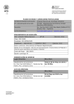
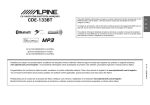
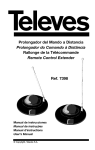
Modem GSM
Manual de instrucciones / User manual
© Copyright, Televés S.A.
ESPAÑOL
Módem GSM
ÍNDICE
1.
Características técnicas
...............................................................................
5
....................................................................................
5
1.2. Características técnicas . . . . . . . . . . . . . . . . . . . . . . . . . . . . . . . . . . . . . . . . . . . . . . . . . . . . . . . . . . . . . . . . . . . . . . . . . . . .
6
1.1. Módem GSM
1.3. Frecuencia de operación . . . . . . . . . . . . . . . . . . . . . . . . . . . . . . . . . . . . . . . . . . . . . . . . . . . . . . . . . . . . . . . . . . . . . . . . . . .
7
1.4. Indicación LEDs . . . . . . . . . . . . . . . . . . . . . . . . . . . . . . . . . . . . . . . . . . . . . . . . . . . . . . . . . . . . . . . . . . . . . . . . . . . . . . . . . .
8
2.
Manejo del producto . . . . . . . . . . . . . . . . . . . . . . . . . . . . . . . . . . . . . . . . . . . . . . . . . . . . . . . . . . . . . . . . . . . . . . . . . . . . . . . . . .
9
3.
Aplicación . . . . . . . . . . . . . . . . . . . . . . . . . . . . . . . . . . . . . . . . . . . . . . . . . . . . . . . . . . . . . . . . . . . . . . . . . . . . . . . . . . . . . . . . . .
10
3
Módem GSM
IMPORTANTES INSTRUCCIONES DE SEGURIDAD
OPERACIÓN SEGURA DEL EQUIPO
CONDICIONES GENERALES DE INSTALACIÓN
• Antes de manipular o conectar el equipo leer este manual.
• Para reducir el riesgo de fuego o choque eléctrico, no exponer el
equipo a la lluvia o a la humedad.
• No quitar la tapa del equipo sin desconectarlo de la red.
• No obstruir las ranuras de ventilación del equipo.
• Deje un espacio libre alrededor del aparato para proporcionar una
ventilación adecuada.
• El aparato no debe ser expuesto a caídas o salpicaduras de agua.
No situar objetos o recipientes llenos de agua sobre o cerca del
aparato si no se tiene la suficiente protección.
• No situar el equipo cerca de fuentes de calor o en ambientes de
humedad elevada.
• No situar el equipo donde pueda estar sometido a fuertes vibraciones o sacudidas.
• La tensión de alimentación de éste producto es de: 230V~ ±15%
50Hz.
• Si algún líquido u objeto se cayera dentro del equipo, por favor
recurra al servicio técnico especializado.
• Para desconectar el equipo de la red, tire del conector, nunca del
cable de red.
• No conectar el equipo hasta que todas las demás conexiones del
equipo hayan sido efectuadas.
• La base de enchufe al que se conecte el equipo debe estar sitúada cerca de éste y será facilmente accesible.
DESCRIPCIÓN DE SIMBOLOGÍA DE SEGURIDAD ELÉCTRICA
• Para evitar el riesgo de choque eléctrico no abrir el equipo.
• Este símbolo indica que el equipo cumple los requerimientos de seguridad para equipos de clase II.
• Este símbolo indica que el equipo cumple los requerimientos del marcado CE.
4
Módem GSM
ref. 5836
(1)
MODEM
GSM/GPRS
PUSH PUSH
SYSTEM
SIM
1
CDC
2
+ 5V
5
PWR
PWR
+ 18V
GND
+ 15V
GND
(4)
ANT
Antena
GSM
STATUS
PWR
3
4
1.- Lector Tarjetas SIM
2.- Conector que implementa
Puerto Serie (Tx/Rx) para
comunicación con CDC (ref. 5059)
3.- Conector de Potencia
4.- LEDS Indicadores PWR y STATUS
5.- Conector F de antena GSM
STATUS
1.1.- MÓDEM GSM
ESPAÑOL
1.- CARACTERÍSTICAS TÉCNICAS
0234013 002
Elemento de cabecera con capacidad para implementar un terminal GSM/GPRS de cúadruple banda, que permite conectarse a una red
GSM/GPRS y poder desarrollar sobre ella servicios tales como:
Telemetría y Telecontrol
Sistemas de Seguridad
Canal de retorno para posibles sistemas Broadcasting Digitales
Sitemas de Comunicación basados en SMS (Short Message Service)
Sistemas basados en comunicaciones IP punto a punto, pudiendo implementar servicios tales como Sockets TCP/UDP, FTP, e-mail,
etc.
5
Módem GSM
1.2.- Características técnicas
Conectores
Interfaz CDC
Conector RJ45 (RS232, sólo TX y RX)
Interfaz SIM
Conector para el Lector Tarjetas SIM
Conector Antena GSM
Conector F Antena GSM
Interfaz Radio GSM
Potencia de Transmisión
GSM-850 / 900
Pico potencia 2W RF (+33 dBm) sobre 50 Ohm
DCS-1800 / PCS-1900
Pico potencia 1W RF (+30 dBm) sobre 50 Ohm.
Referencia Sensibilidad
Antena GSM
GSM-850 / 900
-107 dBm
DCS-1800 / PCS-1900
-106 dBm
Potencia de Entrada
VSWR (standing wave ratio) máx. absoluto
VSWR (standing wave ratio) recomendado
Ganancia Antena
1.5 dBi < Ganancia < 3 dBi (referencia dipolo I/2 )
Impedancia de Antena
Ancho de Banda
50 ohm
80 MHz en EGSM, 150 MHz en GSM 850, 170
MHz en DCS, 140 MHz en la banda PCS
6
> 2W peak power
<= 10:1
<= 2:1
Interfaz Serie
Comandos AT estándar
Baud Rate Máximo
(UART RS232 TX/RX)
Conjunto de Comandos AT Hayes Estándar.
Especificación ETSI GSM 07.07 para comandos AT y comandos GPRS específicos.
Especificación GSM 07.05 de comandos ATpara SMS y CBS (Cell Broadcast Service).
Comandos compatibles con FAX Clase 1.
Niveles CMOS
115,2 Kbps
Potencia / Temperatura
Requerimientos de Potencia
Temperatura de Operación
IP
1.65 W ( 330 mA a 5V) con llamada activa
0.25 W ( 50 mA a 5V) con el módem registrado en Red GSM en espera de llamada
45°C
20
1.3- Frecuencia de Operación
MODO
Frec. TX (MHz)
Frec. RX (MHz)
Canales (ARFC)
TX-RX offset
890.0 - 914.8
935.0 - 959.8
0 - 124
45 MHz
880.2 - 889.8
925.2 - 934.8
975 - 1023
45 MHz
GSM-850
824.2 - 848.8
969.2 - 893.8
128 - 251
45 MHz
DCS-1800
1710.2 - 1784.8
1805.2 - 1879.8
512 - 885
95 MHz
PCS-1900
1850.2 - 1909.8
1930.2 - 1989.8
512 - 810
80 MHz
E-GSM-900
7
ESPAÑOL
Módem GSM
Módem GSM
LED PWR. Indicador de Power ON/OFF
STATUS
PWR
1.4- Indicación LEDs
LED STATUS. Indicación de la disponibilidad de Red. El LED STATUS muestra información sobre de la
disponibilidad de Servicio hacia la Red GSM y el propio estado de la llamada GSM. Se muesta a continuación una tabla.
LED STATUS
Estado Módem GSM/GPRS Ref. 5836
Permanentemente encendido
Llamada Activa
Entrante o Establecida
Secuencia Rápida Parpadeo
(1 segundo)
Búsqueda de Red GSM
Dispostivo NO Registrado
Apagándose
Secuencia Lenta Parpadeo
(3 segundos)
Dispositivo Registrado Red GSM
Permanentemente Apagado
Dispositivo Apagado
8
2. - MANEJO DEL PRODUCTO
El manejo del producto hace referencia al
uso con el CDC Ref. 5059. Los pasos a
seguir para la instalación del módem Ref.
5836 con la ref. 5059 son los siguientes:
a) Mediante el software de cabeceras y
una configuración local, introducir el PIN
(Personal Identification Number) de la
SIM en el CDC Ref. 5059 (Más información en el manual del CDC).
b) Conectar mediante un cable Ethernet
(conexionado directo) el conector exterior RJ45 del Módem GSM y el conector
RJ45 Módem del CDC.
c) Insertar la SIM del operador que se
desee en la entrada al uso.
NOTA:
Es imprescindible para su operatibilidad
con el CDC Ref 5059, disponer de una SIM
(Subscriber Identity Module) con los
Servicios portadores GSM 02.02 activos
por parte del operador, de tal forma que las
llamadas entrantes al Módem GSM/GPRS
sean llamadas identificadas como DATOS y
NO de VOZ.
En algunos casos el operador suele propor-
cionar por SIM, un número telefónico para
las llamadas de Voz y otro para las llamadas de Datos. Hay que tenerlo en cuenta a
la hora de establecer una comunicación
remota (llamar al número de datos) con la
cabecera.
d) Conectar la alimentación en bus.
Comprobar que se enciende el LED PWR
del Módem y ver que el LED STATUS se
enciende y parpadea, como se ha descrito en el punto anterior de los LEDs.
NOTA:
El Módem GSM de Televés soporta la fase
2 del estándar GSM11.14 – SIM de 3
Voltios. La Ref. 5836 posee internamente
un lector de tarjetas SIM que permite el
cambio en “caliente” de las SIM. Por lo
tanto la SIM puede ser extraída y reinsertada mientras el módem está activo.
NOTA:
Cabe destacar, que el tiempo necesario
entre sesiones consecutivas debe ser de 2
minutos, para garantizar que el CDC esté en
disposición de atender una nueva llamada.
9
ESPAÑOL
Módem GSM
Módem GSM
5059
ESPAÑOL
3. - APLICACIÓN
5836
MODEM
GSM/GPRS
SIM
PUSH PUSH
SYSTEM
CDC
SIM
PUSH PUSH
SYSTEM
PWR
ANT
CDC
PWR
STATUS
PWR
SIM
PWR
10
STATUS
0234013 00
Modem GSM
INDEX
1.
Technical specifications . . . . . . . . . . . . . . . . . . . . . . . . . . . . . . . . . . . . . . . . . . . . . . . . . . . . . . . . . . . . . . . . . . . . . . . . . . . . . . . .
13
1.1. Modem GSM
....................................................................................
13
1.2. Technical specifications . . . . . . . . . . . . . . . . . . . . . . . . . . . . . . . . . . . . . . . . . . . . . . . . . . . . . . . . . . . . . . . . . . . . . . . . . . . .
14
15
1.4. LED Indications
..................................................................................
16
2.
Product handling . . . . . . . . . . . . . . . . . . . . . . . . . . . . . . . . . . . . . . . . . . . . . . . . . . . . . . . . . . . . . . . . . . . . . . . . . . . . . . . . . . . . .
17
3.
Application . . . . . . . . . . . . . . . . . . . . . . . . . . . . . . . . . . . . . . . . . . . . . . . . . . . . . . . . . . . . . . . . . . . . . . . . . . . . . . . . . . . . . . . . . .
18
ENGLISH
1.3. Operating Frequency . . . . . . . . . . . . . . . . . . . . . . . . . . . . . . . . . . . . . . . . . . . . . . . . . . . . . . . . . . . . . . . . . . . . . . . . . . . . . .
11
Modem GSM
IMPORTANT SAFETY INSTRUCTIONS
GENERAL INSTALLATION CONDITIONS
HOW TO USE THE EQUIPMENT SAFELY
• Before handling or connecting the equipment, please read this
manual.
• In order to reduce the risk of fire or electric shock, do not expose
the equipment to rain or moisture.
• Do not take the cover off the equipment without disconnecting it
from the mains.
• Do not obstruct the equipment's ventilation system.
• Please allow air circulation around the equipment
• The equipment must not come into contact with water or even be
splashed by liquids. Do not place containers with water on or near
the equipment if it is not adequately protected.
• Do not place the equipment near sources of heat or in excessively
moisture conditions.
• Do not place the equipment where it may be affected by strong
vibrations or knocks.
• The powering supply of this product is: 230V~ ±10% / 50Hz.
• If any liquid or object falls inside the equipment, please contact a
specialized technician.
• To disconnect the equipment from the mains, pull from the connector, and never pull from the cable.
• Do not connect the equipment until all the other connections have
been made.
• The mains socket that is going to be used to connect the equipment should be located nearby and should be easily accessible.
DESCRIPTION OF THE ELECTRICAL SAFETY SYMBOLS
• To avoid the risk of electric shock, do not open the equipment.
• This symbol indicates that the equipment complies with the safety requirements for class II equipment.
• This symbol indicates that the equipment complies with the requirements of CE mark.
12
Modem GSM
1.- TECHNICAL SPECIFICATIONS
ref. 5836
(1)
MODEM
GSM/GPRS
PUSH PUSH
SYSTEM
SIM
1
CDC
2
+ 5V
5
PWR
PWR
+ 18V
GND
+ 15V
GND
(4)
ANT
GSM
aerial
STATUS
PWR
3
4
1.- SIM Card Reader
2.- Connector implementing Serial Port
(Tx/Rx) for communication with Main
Control (ref. 5059)
3.- Power Connector
4.- LEDS PWR and STATUS Indicators
5.- F Connector for GSM aerial
STATUS
1.1.- MODEM GSM
Control device capable of implementing a GSM/GPRS four-band terminal, allowing connection to a GSM/GPRS network and able to carry
out services such as:
Telemetry and Tele-controlling
Safety Systems
Return channel for possible Digital Broadcasting Systems
Communications Systems based on SMS
Systems based on IP point-to-point communications, capable of implementing services such as Sockets TCP/UDP, FTP, e-mail, etc.
13
ENGLISH
0234013 002
Modem GSM
1.2.- Technical specifications
Connectors
Interface CDC
Connector RJ45 (RS232, only TX and RX)
Interface SIM
Connector for SIM Card Reader
GSM Aerial Connector
GSM Aerial F Connector
GSM Radio Interface
Transmission Power
GSM-850 / 900
2W RF Power Peak (+33 dBm) on 50 Ohm
DCS-1800 / PCS-1900
1W RF Power Peak (+30 dBm) on 50 Ohm
Sensitivity Reference
Antena GSM
GSM-850 / 900
-107 dBm
DCS-1800 / PCS-1900
-106 dBm
Input Power
> 2W peak power
<= 10:1
VSWR (standing wave ratio) absolute maximum
<= 2:1
VSWR (standing wave ratio) recommended
Aerial Gain
1.5 dBi < Aerial Gain < 3 dBi (dipole I/2 reference )
Aerial Impedance
Band Width
50 ohm
80 MHz in EGSM, 150 MHz in GSM 850, 170
MHz in DCS, 140 MHz in PCS band
14
Modem GSM
Serial Interface
Standard AT Commands
Baud Rate Máximo
(UART RS232 TX/RX)
Set of AT Hayes Standard Commands
ETSI GSM 07.07 Specification for specific AT and GPRS Commands.
GSM 07.05 Specification for AT Commands for SMS and CBS (Cell Broadcast Service)
Commands that are compatible with Class 1 FAX
CMOS Levels
115,2 Kbps
Power / Temperature
Power Requirements
Operating Temperature
IP
1.65 W ( 330 mA to 5V) with active call
0.25 W ( 50 mA to 5V) with the Modem registered on the GSM network awaiting calls
45°C
20
MODE
Freq. TX (MHz)
Freq. RX (MHz)
Channels (ARFC)
TX-RX offset
890.0 - 914.8
935.0 - 959.8
0 - 124
45 MHz
880.2 - 889.8
925.2 - 934.8
975 - 1023
45 MHz
GSM-850
824.2 - 848.8
969.2 - 893.8
128 - 251
45 MHz
DCS-1800
1710.2 - 1784.8
1805.2 - 1879.8
512 - 885
95 MHz
PCS-1900
1850.2 - 1909.8
1930.2 - 1989.8
512 - 810
80 MHz
E-GSM-900
15
ENGLISH
1.3- Operating Frequency
Modem GSM
LED PWR. Indicator of Power ON/OFF
STATUS
PWR
1.4- LED Indications
LED STATUS. Indication of network availability. The LED STATUS shows information on Service availability toward the GSM network, and the status of the GSM call itself. See the table below.
LED STATUS
State of Modem GSM/GPRS Ref. 5836
Permanently On
Call Active
Incoming or Established
Rapid Blinking Sequence
(1 second)
GSM Network search
NON-Registered Device
Turning off
Slow Blinking Sequence
(3 seconds)
GSM Network Registered Device
Permanently Off
Device Off
16
Modem GSM
2. - PRODUCT HANDLING
a) Using command software and local configuration, introduce the PIN (Personal
Identification Number) of the SIM Card in
the CDC Ref. 5059 (Further information
can be obtained from the CDC Manual).
b) Connect using an Ethernet cable (direct
connection) the external RJ45 Connector
of the GSM Modem and the RJ45
Modem Connector of the CDC.
c) Insert the desired operator SIM Card in
the user port.
NOTE:
For your ability to operate with the CDC
Ref. 5059, you must necessarily have a SIM
(Subscriber Identity Module) card with GSM
02.02 support services enabled by the operator, so that incoming calls to the
GSM/GPRS are DATA and NOT VOICEidentified calls.
In some cases, the operator supplies
through SIM, one phone number for Voice
calls and another one for Data calls. this
must be borne in mind when establishing a
remote communication (call data number)
with control.
d) Bus-connect feed.
Check that the PWR LED on the Modem
lights up and that the STATUS LED lights
up and blinks as described in the previous item on LEDs.
NOTE:
The Televés GSM Modem supports phase 2
of the standard 3-Volt GSM11.14 – SIM.
The Ref. 5836 possesses and internal SIM
Card reader enabling the “hot-status” change of SIMs. Therefore, the SIM Card may be
withdrawn and reinserted while the Modem
is still active.
NOTE:
It should be stressed that the interval
necessary between consecutive sessions
must be of 2 minutes, to guarantee that the
CDC is enabled to attend a new call.
17
ENGLISH
Product handling refers to its use with the
CDC Ref. 5059. The steps to be taken to
install Modem Ref. 5836 with Ref. 5059 are
as follows:
Modem GSM
3. - APPLICATION
5059
5836
MODEM
GSM/GPRS
SIM
PUSH PUSH
SYSTEM
CDC
SIM
PUSH PUSH
SYSTEM
PWR
18
STATUS
0234013 00
ENGLISH
PWR
ANT
CDC
PWR
STATUS
PWR
SIM
Modem GSM
Garantía
Televés S.A. ofrece una garantía de dos años calculados a partir
de la fecha de compra para los países de la UE. En los países no
miembros de la UE se aplica la garantía legal que está en vigor en
el momento de la venta. Conserve la factura de compra para
determinar esta fecha.
Durante el período de garantía, Televés S.A. se hace cargo de los
fallos producidos por defecto del material o de fabricación.
Televés S.A. cumple la garantía reparando o sustituyendo el equipo defectuoso.
No están incluidos en la garantía los daños provocados por uso
indebido, desgaste, manipulación por terceros, catástrofes o cualquier causa ajena al control de Televés S.A.
Televés S.A. offers a one year guarantee, beginning from the date
of purchase for countries in the EEC.
For the batteries and due to the characteristics of this article, the
guarantee period is limited to six months.
For countries that are not part of the EEC, the legal guarantee that
is in force at the time of purchase is applied.
Keep the purchase invoice to determine this date.
During the guarantee period, Televés S.A. becomes position of the
failures produced by defect of the material or manufacture.
The harm produced by improper usage, wear and tear, manipulation by a third party, catastrophes or any other cause beyond the
control of Televés S.A. is not included in the guarantee
Televés S.A. / Rúa Benéfica de Conxo, 17 / 15706 Santiago de
Compostela / Spain / [email protected]
19
ENGLISH
Guarantee
RED COMERCIAL - COMMERCIAL NETWORK
UNITED KINGDOM
TELEVES (UK) Ltd.
11 Hill Street Industrial Estate
Cwmbran, Gwent NP44 7PG
UNITED KINGDOM
Telephone: +44 1633 875821
Fax: +44 1633 866311
EMail: [email protected]
FRANCE
POLSKA
TELEVES FRANCE Sarl
1 Rue Louis de Broglie
Parc d'Activités de l'Esplanade
77400 St. Thibault des Vignes
FRANCE
Telephone: +33 1 6035 9210
Fax: +33 1 6035 9040
EMail: [email protected]
TELEVES POLSKA Sp. z o. o.
Ul. Bardzka 60
50-517 Wroclaw
Telephone : +48 71 7901 115
Fax : +48 71 7901 112
EMail: [email protected]
GERMANY
TELEVES DEUTSCHLAND GmbH
An den Kiesgruben 6, 73240 Wendlingen
DEUTSCHLAND
Telephone: +49 7024 55358
Fax: +49 7024 6295
EMail: [email protected]
Sucursales / Distributors
Para conocer nuestra red de
sucursales en el mundo,
le rogamos consulte en
nuestra pagina web
Please visit Televés web site
to find your nearest
Official Distributor
CHINA
TELEVES CHINA
Unit 207-208, Building A, No 374
Wukang Rd, Xuhui District
200031 Shanghai
CHINA (P.R.C.)
Telephone: +86 21 6126 7620
Fax: +86 21 6466 6431
EMail: [email protected]
USA
TELEVES USA LLC.
9800 Mount Pyramid Court, Suite 400
80112 Englewood, CO
USA
Telephone : +1 303 256 6767
Fax : +1 303 256 6769
EMail: [email protected]
Rúa Benéfica de Conxo, 17
15706 - Santiago de Compostela
ESPAÑA (SPAIN)
Tel: +34 981 52 22 00
Fax: +34 981 52 22 62
PORTUGAL
ITALY
MIDDLE EAST
TELEVES ELECTRONICA PORTUGUESA
Via Dr. Francisco Sa Carneiro, Lote 17
Zona Ind. Maia 1 Sector X
4470 Barca-Maia-Porto
PORTUGAL
Telephone: +351 22 94 78900
Fax: +351 22 94 78900
EMail: [email protected]
TELEVES ITALIA Srl.
Via Liguria 24
2068 Peschiera Borromeo (MI)
ITALIA
Telephone: +39 02 5165 0604
Fax: +39 02 5530 7363
EMail: [email protected]
TELEVES MIDDLE EAST FZE
P.O. Box 17199 Jebel Ali Free Zone
Dubai
UNITED ARAB EMIRATES
Telephone: +971 48 834 344
Fax: +971 48 834 644
EMail: [email protected]
[email protected]
www.televes.com
Miembro de número del
Oficinas Centrales / Head Office
Delegaciones / Subsidiaries
Empresa
Registrada
ER 224/1/94