1
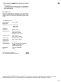
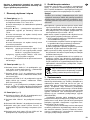
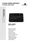
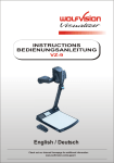
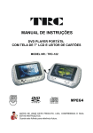
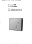
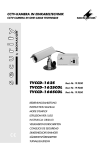
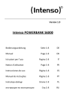
VIDEO-VGA-KONVERTER
VIDEO VGA CONVERTER
VTM-20
Best.-Nr. 19.9900
BEDIENUNGSANLEITUNG
INSTRUCTION MANUAL
MODE D’EMPLOI
ISTRUZIONI PER L’USO
MANUAL DE INSTRUCCIONES
INSTRUKCJA OBSŁUGI
VEILIGHEIDSVOORSCHRIFTEN
SIKKERHEDSOPLYSNINGER
SÄKERHETSFÖRESKRIFTER
TURVALLISUUDESTA
®
D
A
CH
F
B
CH
Bevor Sie einschalten ...
GB
Wir wünschen Ihnen viel Spaß mit Ihrem neuen
Gerät von MONACOR. Dabei soll Ihnen diese
Bedienungsanleitung helfen, alle Funktionsmöglichkeiten kennen zu lernen. Die Beachtung der
Anleitung vermeidet außerdem Fehlbedienungen und schützt Sie und Ihr Gerät vor eventuellen Schäden durch unsachgemäßen Gebrauch.
Der deutsche Text beginnt auf der Seite 4.
Avant toute mise en service ...
We wish you much pleasure with your new
MONACOR unit. With these operating instructions you will be able to get to know all functions
of the unit. By following these instructions false
operations will be avoided, and possible
damage to yourself and your unit due to improper use will be prevented.
The English text starts on page 7.
I
Nous vous remercions d’avoir choisi un appareil
MONACOR et vous souhaitons beaucoup de
plaisir à l’utiliser. Cette notice a pour objectif de
vous aider à mieux connaître les multiples facettes de l’appareil et à vous éviter toute mauvaise
manipulation.
NL
B
S
Antes de cualquier instalación ...
PL
Przed Uruchomieniem ...
Tenemos de agradecerle el haber adquirido un
aparato MONACOR y le deseamos un agradable uso. Este manual quiere ayudarle a conocer
las multiples facetas de este aparato. La observación de las instrucciones evita operaciones
erróneas y protege Vd. y vuestro aparato contra
todo daño posible por cualquier uso inadecuado.
Życzymy zadowolenia z nowego produktu
MONACOR. Dzięki tej instrukcji obsługi będą
państwo w stanie poznać wszystkie funkcje tego
urządzenia. Stosując się do instrukcji unikną
państwo błędów i ewentualnego uszkodzenia
urządzenia na skutek nieprawidłowego użytkowania.
La versión española comienza en la página 16.
Tekst polski zaczyna się na stronie 19.
Voordat u inschakelt ...
DK
Wij wensen u veel plezier met uw nieuw toestel
van MONACOR. Lees de veiligheidsvoorschriften, alvorens het toestel in gebruik te
nemen. Door de veiligheidsvoorschriften op te
volgen zal een slechte werking vermeden worden, en zal een eventueel letsel aan uzelf en
schade aan uw toestel tengevolge van onzorgvuldig gebruik worden voorkomen.
U vindt de veiligheidsvoorschriften op pagina 22.
Förskrift
Vi önskar dig mycket nöje med din nya enhet
från MONACOR. Läs gärna säkerhetsinstruktionerna innan du använder enheten. Genom att
följa säkerhetsistruktionerna kan många problem undvikas, vilket annars kan skada enheten.
Du finner säkerhetsinstruktionerna på sidan 23.
2
Prima di accendere ...
Vi auguriamo buon divertimento con il Vostro
nuovo apparecchio MONACOR. Le istruzioni per
l’uso Vi possono aiutare a conoscere tutte le possibili funzioni. E rispettando quanto spiegato
nelle istruzioni, evitate di commettere degli errori,
e così proteggete Voi stessi, ma anche l’apparecchio, da eventuali rischi per uso improprio.
Il testo italiano inizia a pagina 13.
La version française commence à la page 10.
E
Before you switch on ...
Inden De tænder for apparatet ...
Vi ønsker Dem god fornøjelse med Deres nye
MONACOR apparat. Læs oplysningerne for en
sikker brug af apparatet før ibrugtagning. Følg
sikkerhedsoplysningerne for at undgå forkert
betjening og for at beskytte Dem og Deres
apparat mod skade på grund af forkert brug.
Sikkerhedsoplysningerne finder De på side 22.
FIN
Ennen virran kytkemistä ...
Toivomme, että uusi MONACOR-laitteesi tuo
sinulle paljon iloa ja hyötyä. Ole hyvä ja lue käyttöohjeet ennen laitteen käyttöönottoa. Luettuasi
käyttöohjeet voit käyttää laitetta turvallisesti ja
vältyt laitteen väärinkäytöltä.
Käyttöohjeet löydät sivulta 23.
☛/ Source
➀
1
➁
➂
3
Audio in
C-in
S-in
6
7
8
▼/ Freq.
▲/i
2
3 4
5
9
DC 9V
VGA in
Monitor
Line-in
SPK out
10
11
12
13
14
D
A
Bitte klappen Sie die Seite 3 heraus. Sie sehen
dann immer die beschriebenen Bedienelemente
und Anschlüsse.
CH
1
Bedienelemente und Anschlüsse
1.1 Oberseite (Abb. 1)
1 Taste ☛/Source schaltet zwischen den beiden
Videoeingängen „C-in“ und „S-in“ um
im Bildschirmmenü: zur Bestätigung einer angewählten Menüfunktion
2 Taste ▼/Freq. schaltet zwischen den beiden Bildfrequenzen 60 Hz und 75 Hz für das konvertierte
Videosignal um
im Bildschirmmenü: zum Anwählen der Menüfunktionen und zum Ändern von Einstellungen
3 Taste ▲/i zum Einblenden der Eigenschaften des
aktuellen Videosignals
im Bildschirmmenü: zum Anwählen der Menüfunktionen und zum Ändern von Einstellungen
4 Betriebsanzeige für den Videokonverter
ein: konvertiertes Videosignal von „C-in“ bzw.
„S-in“ und Audiosignale an „Audio-in“ werden
ausgegeben
aus: Signale an „VGA-in“ und „Line-in“ werden
ausgegeben
5 Taste zum Aufrufen und Verlassen des Bildschirmmenüs
2
Achtung!
Das Netzgerät wird mit lebensgefährlicher Netzspannung (230 V~) versorgt. Nehmen Sie deshalb nie
selbst Eingriffe in dieses Gerät vor. Durch unsachgemäßes Vorgehen besteht die Gefahr eines elektrischen Schlages. Außerdem erlischt beim Öffnen des
Konverters oder des Netzgerätes jeglicher Garantieanspruch.
●
Setzen Sie den Konverter und das Netzgerät nur im
Innenbereich ein und schützen Sie die Geräte vor
Tropf- und Spritzwasser, hoher Luftfeuchtigkeit und
Hitze (zulässiger Einsatztemperaturbereich 0 – 40 °C).
●
Nehmen Sie den Konverter nicht in Betrieb bzw. ziehen Sie das Netzgerät sofort aus der Steckdose:
1. wenn sichtbare Schäden an dem Konverter oder
am Netzgerät vorhanden sind,
2. wenn nach einem Sturz oder Ähnlichem der Verdacht auf einen Defekt besteht,
3. wenn Funktionsstörungen auftreten.
Lassen Sie den Konverter oder das Netzgerät in
jedem Fall in einer Fachwerkstatt reparieren.
●
Verwenden Sie für die Reinigung nur ein trockenes,
weiches Tuch, niemals Chemikalien oder Wasser.
●
Werden der Konverter oder das Netzgerät zweckentfremdet, falsch angeschlossen bzw. bedient oder nicht
fachgerecht repariert, kann keine Haftung für daraus
resultierende Sach- oder Personenschäden und keine
Garantie für die Geräte übernommen werden.
1.2 Vorderseite (Abb. 2)
6 Cinch-Buchsen „Audio in“ zum Anschluss des
Audiosignals der Videoquelle an „C-in“ (7) oder
„S in“ (8)
7 Cinch-Buchse „C-in“ zum Anschluss einer Videoquelle (z. B. Kamera, Videorecorder, DVD-Player,
Spielekonsole) mit FBAS-Signal (composite)
8 Mini-DIN-Buchse „S-in“ zum Anschluss einer
Videoquelle (z.B. Kamera, Videorecorder, DVDPlayer, Spielekonsole) mit S-Video-Signal
9 Taste
zum Umschalten zwischen Videokonverter-Betrieb und PC-Durchschleifbetrieb (siehe
Kap. 1.1, Punkt 4 „Betriebsanzeige“)
1.3 Rückseite (Abb. 3)
10 Versorgungsbuchse „DC 9V“ zum Anschluss des
mitgelieferten Steckernetzgerätes
11 D-SUB-Buchse „VGA in“ zum Anschluss eines PC
12 D-SUB-Buchse „Monitor“ zum Anschluss an den
Monitor
13 3,5-mm-Stereo-Klinkenbuchse „Line-in“ zum Anschluss an die Line-out-Buchse (Audioausgang)
eines PC
14 3,5-mm-Stereo-Klinkenbuchse „SPK out“, Audioausgang z. B. zum Anschluss von Aktivlautsprechern
4
Hinweise für den sicheren Gebrauch
Der Konverter und das beiliegende Steckernetzgerät
entsprechen der Richtlinie für elektromagnetische Verträglichkeit 89/336/EWG. Das Netzgerät entspricht
zusätzlich der Niederspannungsrichtlinie 73/23/EWG.
Sollen der Konverter und das Netzgerät
endgültig aus dem Betrieb genommen
werden, übergeben Sie die Geräte zur umweltgerechten Entsorgung einem örtlichen
Recyclingbetrieb.
3
Einsatzmöglichkeiten
Mit diesem Konverter lassen sich Signale beliebiger
Videoquellen, wie z. B. Kameras, Videomultiplexer,
Videorecorder, DVD-Player oder Spielekonsolen, in
ein VGA-Signal umwandeln und auf einem PC-Monitor
darstellen. Das Videosignal kann im FBAS-Format
(composite) oder im S-Video-Format vorliegen. Per
Tastendruck lässt sich zwischen den beiden Videoeingängen umschalten. Dabei stellt sich das Gerät automatisch auf die Videonorm des anliegenden Signals
(PAL oder NTSC) ein.
Der Konverter besitzt zusätzlich einen VGA-Durchschleifeingang für den Anschluss eines PC sowie
Audioeingänge und -ausgänge, sodass zwischen den
konvertierten Videosignalen und dem VGA-Signal des
PC sowie den dazugehörigen Audiosignalen umgeschaltet werden kann. Ein VGA-Kabel und ein Audiokabel für die Verbindungen vom PC zum Konverter
werden mitgeliefert.
Über ein Bildschirmmenü lässt sich der Konverter
auf vielfältige Weise an die Bedürfnisse des Anwenders anpassen. Es lassen sich Helligkeit, Kontrast,
Farbe, Bildschärfe, Auflösung, Bildfrequenz und Bildschirmtyp einstellen.
4
Anschluss
Alle Anschlüsse dürfen nur bei ausgeschalteten Geräten durchgeführt werden!
1) Die Videoquelle an die Eingangsbuchse „C-in“ (7)
oder „S-in“ (8) anschließen. Sind beide Eingänge
mit unterschiedlichen Videoquellen belegt, kann
jederzeit per Tastendruck zwischen den beiden
umgeschaltet werden.
2) Den Monitor an die Buchse „Monitor“ (12) anschließen.
3) Den VGA-Ausgang des PC an die Buchse „VGA in“
(11) anschließen.
4) Den Audio-Ausgang des PC mit der Buchse „Linein“ (13) verbinden.
5) Den Audio-Ausgang der Videoquelle an die Buchsen „Audio in“ (6) anschließen.
6) Die Aktivlautsprecher des PC oder einen externen
Audioverstärker an die Buchse „SPK out“ (14)
anschließen.
7) Den Kleinspannungsstecker des Netzgerätes mit
der Buchse „DC 9V“ (10) verbinden und das Netzgerät in eine Netzsteckdose stecken.
Hinweis: Dient der VTM-20 lediglich als Konverter für
das Videosignal und soll er nicht wechselweise mit
einem PC an einem Monitor betrieben werden, kann
auf die Anschlüsse der Punkte 3)–6) verzichtet werden.
5
Bedienung
Ist die Taste
(9) nicht gedrückt [die Betriebsanzeige
(4) leuchtet nicht], werden die durchgeschleiften Signale an „VGA-in“ und „Line-in“ ausgegeben. Alle Einstellmöglichkeiten des Konverters haben keinerlei Einfluss
auf die durchgeschleiften Signale.
1) Mit der Taste
(9) den Konverter aktivieren. Die
Betriebsanzeige (4) leuchtet. Es wird nun das konvertierte Videosignal auf dem Monitor dargestellt.
Gleichzeitig werden die Audiosignale an den Buchsen „Audio in“ (6) auf den Ausgang „SPK out“ (14)
geschaltet.
2) Zum Umschalten zwischen den beiden Videoeingängen „C-in“ (7) und „S-in“ (8) die Taste ☛/Source (1)
drücken.
3) Zum Umschalten zwischen den beiden Bildfrequenzen 60 Hz und 75 Hz für die Ausgabe des
Videosignals die Taste ▼/Freq. (2) drücken.
4) Mit der Taste ▲/i (3) werden für ca. 5 s Informationen zum aktuellen Videosignal eingeblendet:
Videoeingang („CVBS“=“C-in“ / „S-VIDEO“=“S-in“)
Videonorm (PAL / NTSC)
Bildfrequenz (60 Hz / 75 Hz)
Bildauflösung (1024 x 768/800 x 600/640 x 480)
5) Um die Bildeinstellungen (Helligkeit, Kontrast, Farbe usw.) durchzuführen, das Bildschirmmenü aufrufen – siehe dazu Kap. 5.1.
D
A
CH
5.1 Einstellungen im Bildschirmmenü
Mit der Taste (5) das Menü aufrufen. Mit derselben
Taste kann das Menü jederzeit wieder verlassen werden. Wird bei eingeblendetem Menü länger als 15 s
keine Taste gedrückt, blendet sich das Menü automatisch wieder aus.
Das Menü:
BRIGHTNESS
Bildhelligkeit
CONTRAST
Kontrast
COLOR
Farbintensität
HUE
Farbton
SHARPNESS
Bildschärfe
RESOLUTION
Bildauflösung
FREQUENCY
Bildfrequenz
MONITOR
Monitortyp
RESET
Rücksetzen aller Einstellungen
Die gewünschte Menüfunktion mit den Tasten ▼/Freq.
(2) oder ▲/i (3) anwählen und mit der Taste ☛/Source
(1) bestätigen. Die angewählte Funktion ist rot markiert.
Anschließend die Einstellung mit den Pfeiltasten (2
oder 3) vornehmen.
1) Zum Einstellen von Bildhelligkeit (BRIGHTNESS),
Kontrast (CONTRAST), Farbintensität (COLOR),
Farbton (HUE) und Bildschärfe (SHARPNESS) die
jeweilige Funktion aufrufen (mit den Pfeiltasten ▲
und ▼ anwählen und mit ☛ bestätigen) und anschließend mit den Pfeiltasten den gewünschten
Wert (min. 0 bis max. 100, bei SHARPNESS: 0 bis
15) einstellen: Zum Erhöhen des Wertes die Taste
▲/i (3) drücken, zum Reduzieren des Wertes die
Taste ▼/Freq. (2).
2) Für eine Änderung der Bildauflösung (horizontale
und vertikale Anzahl der Bildpunkte im konvertierten
Videosignal) die Funktion RESOLUTION aufrufen.
Mit den Tasten ▲/i (3) und ▼/Freq. (2) kann zwischen den folgenden Auflösungen gewählt werden:
1024 x 768, 800 x 600 und 640 x 480.
Der aktuelle Wert ist farbig unterlegt dargestellt.
3) Über die Funktion FREQUENCY kann, wie mit der
Taste ▼/Freq. (2) außerhalb des Menüs, zwischen
den beiden Bildfrequenzen 60 Hz und 75 Hz für die
Ausgabe des Videosignals umgeschaltet werden.
Dazu die Taste ▲/i (3) oder ▼/Freq. (2) drücken.
Der aktuelle Wert ist farbig unterlegt dargestellt.
4) Über die Funktion MONITOR kann der Typ des verwendeten Monitors gewählt werden. Zur Auswahl
stehen LCD (Flüssigkeitskristallanzeige) und CRT
(Kathodenstrahlröhre).
Mit der Taste ▲/i (3) oder ▼/Freq. (2) den zutreffenden Monitortyp auswählen. Der aktuell eingestellte Typ ist farbig unterlegt dargestellt.
5) Über die Funktion SOURCE kann, wie mit der
Taste ☛/Source (1) außerhalb des Menüs, zwischen den beiden Videoeingängen „CVBS“=„C-in“
(7) und „S-VIDEO“=„S-in“ (8) umgeschaltet werden.
5
D
A
CH
Dazu die Taste ▲/i (3) oder ▼/Freq. (2) drücken.
Der gewählte Eingang ist farbig unterlegt dargestellt.
6) Für das Zurücksetzen der Menüeinstellungen die
Funktion RESET anwählen und mit der Taste
☛/Source (1) bestätigen.
Diese Funktion löscht alle vom Anwender vorgenommenen Einstellungen und ersetzt sie durch die
Werkseinstellung.
5.2 Nach dem Gebrauch
Da das Gerät auch im Durchschleifbetrieb einen geringen Strom verbraucht, ist es ratsam, nach dem
Gebrauch das Netzgerät aus der Steckdose zu ziehen.
6
Technische Daten
Videonormen: . . . . PAL, NTSC
Auflösungen
(Bildpunkte
hor. x vert.):. . . . . . 1024 x 768
800 x 600
640 x 480
Bildfrequenzen:. . . 60 Hz, 75 Hz
Videoeingänge:. . . Cinch, FBAS (composite)
Mini-DIN, S-Video
D-SUB, 15-pol., VGA
Audioeingänge:. . . Cinch, stereo
3,5-mm-Klinke, stereo
Videoausgang: . . . D-SUB, 15-pol., VGA
Audioausgang: . . . 3,5-mm-Klinke, stereo
Einsatztemperatur: 0 – 40 °C
Stromversorgung: . 9 V , 600 mA über beiliegendes
Netzgerät an 230 V~/50 Hz/5 VA
Abmessungen: . . . 170 x 30 x 110 mm
Gewicht: . . . . . . . . 225 g
Laut Angaben des Herstellers.
Änderungen vorbehalten.
Diese Bedienungsanleitung ist urheberrechtlich für MONACOR ® INTERNATIONAL GmbH & Co. KG geschützt.
Eine Reproduktion für eigene kommerzielle Zwecke – auch auszugsweise – ist untersagt.
6
Please unfold page 3. Then you can always see the
operating elements and connections described.
1
Operating Elements and Connections
1.1 Upper side (fig. 1)
1 Button ☛/Source to switch between the two video
inputs “C-in” and “S-in”.
in the on-screen menu: to confirm a selected menu
function
2 Button ▼/Freq. to switch between the two picture
frequencies 60 Hz and 75 Hz for the converted
video signal
in the on-screen menu: to select the menu functions and to change adjustments
3 Button ▲/i to insert the features of the present
video signal
in the on-screen menu: to select the menu functions and to change adjustments
4 Power LED for the video converter
on:
converted video signal from “C-in” or “S-in”
and audio signals at “Audio-in” are sent to
the output
off:
signals at “VGA-in” and “Line-in” are sent to
the output
5 Button to call and exit the on-screen menu
2
●
●
●
●
1.3 Rear side (fig. 3)
10 Supply jack “DC 9V” for connection of the supplied
plug-in power supply unit
11 D-SUB jack “VGA in” for connection of a PC
12 D-SUB jack “Monitor” for connection to the monitor
13 3.5 mm stereo jack “Line-in” for connection to the
line-out jack (audio output) of a PC
14 3.5 mm stereo jack “SPK out”, audio output e. g. for
connection of active speakers
GB
Attention!
The power supply unit is supplied with hazardous
mains voltage (230 V~). Leave servicing to skilled
personnel only. Inexpert handling may cause an electric shock hazard. Furthermore, any guarantee claim
will expire if the converter or the power supply unit
has been opened.
1.2 Front side (fig. 2)
6 Phono jacks “Audio in” for connection of the audio
signal of the video source at “C-in” (7) or “S-in” (8)
7 Phono jack “C-in” for connection of a video source
(e. g. camera, video recorder, DVD player, games
console) with composite signal
8 Mini DIN jack “S-in” for connection of a video source
(e. g. camera, video recorder, DVD player, games
console) with S-video signal
9 Button
for switching between video converter
operation and PC feed-through operation (see
chapter 1.1, item 4 “Power LED”)
Safety Notes
The converter and the supplied plug-in power supply
unit correspond to the directive 89/336/EEC for electromagnetic compatibility. The power supply unit additionally corresponds to the low voltage directive
73/23/EEC.
The converter and the power supply unit are suitable
for indoor use only. Protect them against dripping
water and splash water, high air humidity, and heat
(admissible ambient temperature range 0–40 °C).
Do not set the converter into operation, and immediately disconnect the power supply unit from the
mains socket if
1. there is visible damage to the converter or the
power supply unit,
2. a defect might have occurred after a drop or similar accident,
3. there are malfunctions.
The converter and the power supply unit must in any
case be repaired by skilled personnel.
For cleaning only use a dry, soft cloth, by no means
chemicals or water.
No guarantee claims for the converter or the power
supply unit and no liability for any resulting personal
damage or material damage will be accepted if the
units are used for other purposes than originally
intended, if they are not correctly connected, operated, or not repaired in an expert way.
If the converter and the power supply unit
are to be put out of operation definitively,
take them to a local recycling plant for a
disposal which is not harmful to the environment.
3
Applications
This converter allows to convert signals of any desired
video sources, e. g. cameras, video multiplexers, video
recorders, DVD players, or games consoles, into a
VGA signal and to display them on a PC monitor. The
video signal can be available in the composite format
or in the S-video format. By pressing a button it is possible to switch between both video inputs. Then the
unit automatically adjusts itself to the video standard of
the applied signal (PAL or NTSC).
The converter additionally has a VGA feed-through
input for the connection of a PC and audio inputs and
audio outputs so that it is possible to switch between
the converted video signals and the VGA signal of the
PC and the corresponding audio signals. A VGA cable
and an audio cable for the connections from the PC to
the converter are supplied.
7
GB
Via an on-screen menu the converter can be adapted to the requirements of the user in a versatile way. It
is possible to adjust brightness, contrast, colour, picture sharpness, resolution, picture frequency, and
monitor type.
4
Connection
All connections must only be made with the units
switched off!
1) Connect the video source to the input jack “C-in” (7)
or “S-in” (8). If different video sources are connected to the two inputs, it is possible to switch between them at any time by pressing a button.
2) Connect the monitor to the jack “Monitor” (12).
3) Connect the VGA output of the PC to the jack “VGA
in” (11).
4) Connect the audio output of the PC to the jack
“Line-in” (13).
5) Connect the audio output of the video source to the
jacks “Audio in” (6).
6) Connect the active speaker of the PC or an external
audio amplifier to the jack “SPK out” (14).
7) Connect the low voltage plug of the power supply
unit to the jack “DC 9V” (10) and the power supply
unit to a mains socket.
Note: If the VTM-20 only serves as a converter for the
video signal and if it is not to be operated alternately
with a PC at a monitor, the connections of items 3) to
6) are not necessary.
5
Operation
If the button
(9) is not pressed [the operating indication (4) does not light up], the fed-through signals at
“VGA in” and “Line-in” are sent to the output. Any adjusting possibilities of the converter will not have any
effect on the fed-through signals.
1) Activate the converter with the button
(9). The
power LED (4) lights up. Now the converted video
signal is displayed on the monitor. At the same time
the audio signals at the jacks “Audio in” (6) are sent
to the output “SPK out” (14).
2) To switch between the two video inputs “C-in” (7)
and “S-in” (8), press the button ☛/Source (1).
3) To switch between the two picture frequencies
60 Hz and 75 Hz for the output of the video signal,
press the button ▼/Freq. (2).
4) With the button ▲/i (3) information on the present
video signal is inserted for approx. 5 s:
video input (“CVBS” = “C-in”/“S-VIDEO” = “S-in”)
video standard (PAL/NTSC)
picture frequency (60 Hz/75 Hz)
picture resolution (1024 x 768/800x600/640x480)
5) To make the picture adjustments (brightness, contrast, colour, etc.), call the on-screen menu – for this
purpose see chapter 5.1.
8
5.1 Adjustments in the on-screen menu
Call the menu with the button (5). With the same
button the menu can be exited at any time. If no button
is pressed for more than 15 s with the menu inserted,
the menu will be automatically extinguished.
The menu:
BRIGHTNESS
CONTRAST
COLOR
HUE
SHARPNESS
RESOLUTION
FREQUENCY
MONITOR
RESET
Select the desired menu function with the buttons
▼/Freq. (2) or ▲/i (3) and confirm with the button
☛/Source (1). The selected function has a red marking. Then make the adjustment with the arrow keys (2
or 3).
1) To adjust the BRIGHTNESS, CONTRAST, COLOR
intensity, HUE, and the picture SHARPNESS, call
the respective function (select it with the arrow keys
▲ and ▼ and confirm with ☛) and then adjust the
desired value (min. 0 to max. 100, for SHARPNESS: 0 to 15) with the arrow keys: to increase the
value, press the button ▲/i (3), to decrease the
value, the button ▼/Freq. (2).
2) For a change of the picture resolution (horizontal
and vertical number of the pixels in the converted
video signal), call the function RESOLUTION.
With the buttons ▲/i (3) and ▼/Freq. (2) it is
possible to select between the following resolutions: 1024 x 768, 800 x 600, and 640 x 480.
The present value is highlighted in colour.
3) Via the function FREQUENCY it is possible to
switch between the two picture frequencies 60 Hz
and 75 Hz for the output of the video signal. The
same is possible with the button ▼/Freq. (2) outside
the menu.
For this purpose press the button ▲/i (3) or
▼/Freq. (2). The present value is highlighted in
colour.
4) Via the function MONITOR the type of the monitor
used can be selected. LCD (liquid crystal display)
and CRT (cathode ray tube) are available for selection.
With the button ▲/i (3) or ▼/Freq. (2) select the
corresponding monitor type. The type currently
adjusted is highlighted in colour.
5) Via the function SOURCE it is possible to switch
between the two video inputs “CVBS” = “C-in” (7)
and “S-VIDEO” = “S-in” (8). The same is possible
with the button ☛/Source (1) outside the menu.
For this purpose press the button ▲/i (3) or
▼/Freq. (2). The selected input is highlighted in
colour.
6) To reset the menu adjustments, select the function
RESET and confirm with the button ☛/Source (1).
This function deletes all adjustments made by
the user and replaces them by the factory settings.
GB
5.2 After use
As the unit has a low current consumption even in the
feed-through operation, it is recommended to disconnect the power supply unit from the mains socket
after use.
6
Specifications
Video standards:. . PAL, NTSC
Resolutions
(pixels hor. x vert.): 1024 x 768
800 x 600
640 x 480
Picture frequencies: 60 Hz, 75 Hz
Video inputs: . . . . . phono, composite
mini DIN, S-video
D-SUB, 15-pole, VGA
Audio inputs: . . . . . phono, stereo
3.5 mm jack, stereo
Video output:. . . . . D-SUB, 15-pole, VGA
Audio output:. . . . . 3.5 mm jack, stereo
Ambient
temperature: . . . . . 0 – 40 °C
Power supply: . . . . 9 V , 600 mA via supplied
power supply unit connected to
230 V~/50 Hz/5 VA
Dimensions: . . . . . 170 x 30 x 110 mm
Weight: . . . . . . . . . 225 g
According to the manufacturer.
Subject to technical modification.
All rights reserved by MONACOR ® INTERNATIONAL GmbH & Co. KG. No part of this instruction manual may
be reproduced in any form or by any means for any commercial use.
9
F
B
Ouvrez le présent livret page 3 de manière à visualiser les éléments et branchements.
CH
1
Eléments et branchements
1.1 Face supérieure (schéma 1)
1 Touche ☛/Source : commute entre les deux entrées vidéo “C-in” et “S-in”
Sur le menu écran : pour confirmer une fonction du
menu sélectionné
2 Touche ▼/Freq. : commute entre les deux fréquences d’images 60 Hz et 75 Hz pour le signal vidéo
converti
Sur le menu écran : pour sélectionner les fonctions
du menu et pour modifier les réglages
3 Touche ▲/i pour afficher les propriétés du signal
vidéo actuel
Sur le menu écran : pour sélectionner les fonctions
du menu et pour modifier les réglages
4 Témoin de fonctionnement pour le convertisseur
vidéo
marche : le signal vidéo converti de “C-in” ou
“S-in” et les signaux audio à “Audio-in”
sont envoyés à la sortie
arrêt :
les signaux à “VGA-in” et “Line-in” sont
envoyés à la sortie
5 Touche pour appeler et quitter le menu écran
2
Attention !
Le bloc secteur est alimenté par une tension dangereuse 230 V~. Ne touchez jamais l’intérieur de l’appareil car, en cas de mauvaise manipulation, vous
pourriez subir une décharge électrique mortelle. En
outre, l’ouverture de l’appareil ou du bloc secteur
rend tout droit à la garantie caduque.
●
●
●
●
1.2 Face avant (schéma 2)
6 Prises RCA “Audio in” pour brancher le signal audio
de la source vidéo à “C-in” (7) ou “S-in” (8)
7 Prise RCA “C-in” pour brancher une source vidéo
(p. ex. caméra, magnétoscope, lecteur DVD, console de jeu) avec signal composite
8 Mini prise DIN “S-in” pour brancher une source
vidéo (par exemple caméra, magnétoscope, lecteur DVD, console de jeu) avec signal S-VHS
9 Touche
pour commuter entre fonctionnement
convertisseur vidéo et fonctionnement repiquage
PC (voir chapitre 1.1, point 4 “témoin de fonctionnement”)
1.3 Face arrière (schéma 3)
10 Prise d’alimentation “DC 9V” pour brancher le bloc
secteur livré
11 Prise D-SUB “VGA in” pour brancher un PC
12 Prise D-SUB “Monitor” pour brancher au moniteur
13 Prise jack 3,5 stéréo “Line-in” pour brancher à la
prise Line out (sortie audio) d’un PC
14 Prise jack 3,5 stéréo “SPK out “, sortie audio par
exemple pour brancher des haut-parleurs actifs
10
Conseils d’utilisation et de sécurité
Le convertisseur et le bloc secteur livré répondent à la
norme européenne 89/336/CEE relative à la compatibilité électromagnétique ; le bloc secteur répond en
plus à la norme européenne 73/23/CEE portant sur
les appareils à basse tension.
Ne faites fonctionner le convertisseur et le bloc secteur qu’en intérieur et protégez-les de tout type de
projections d’eau, des éclaboussures, d’une humidité élevée et la chaleur (plage de température de
fonctionnement autorisée : 0 – 40 °C).
Ne faites pas fonctionner le convertisseur ou débranchez immédiatement le bloc secteur du secteur
lorsque :
1. des dommages apparaissent sur le convertisseur
ou le bloc secteur
2. après une chute ou un cas similaire, vous avez un
doute sur l’état de l’appareil,
3. des dysfonctionnements apparaissent.
Faites toujours appel à un technicien spécialisé pour
effectuer les réparations.
Pour le nettoyage, utilisez un chiffon sec et doux, en
aucun cas, de produits chimiques ou d’eau.
Nous déclinons toute responsabilité en cas de dommages matériels ou corporels résultants si le convertisseur ou le bloc secteur est utilisé dans un but
autre que celui pour lequel il a été conçu, s’il n’est
pas correctement branché, utilisé ou n’est pas
réparé par une personne habilitée, en outre, la
garantie deviendrait caduque.
Lorsque le convertisseur et le bloc secteur
sont définitivement retirés du service, vous
devez les déposer dans une usine de recyclage adaptée pour contribuer à leur élimination non polluante.
3
Possibilités d’utilisation
Avec ce convertisseur, on peut convertir des signaux
de sources vidéo au choix, p. ex. caméras, multiplexeurs vidéo, enregistreurs vidéo, lecteurs DVD,
consoles de jeu, en un signal VGA et les afficher sur un
moniteur de PC. Le signal vidéo peut être au format
composite ou au format S-VHS. Par pression sur la
touche, on peut commuter entre les deux entrées
vidéo. L’appareil se règle automatiquement sur la
norme vidéo du signal présent (PAL ou NTSC).
Le convertisseur possède, en plus, une entrée VGA
pour repiquage pour brancher un PC et des entrées et
sorties audio de sorte qu’on puisse commuter entre les
signaux vidéo convertis et le signal VGA du PC et
entre les signaux audio correspondants. Un cordon
VGA et un cordon audio pour les liaisons du PC au
convertisseur sont livrés.
Via le menu écran, le convertisseur peut être adapté de multiples façons aux besoins de l’utilisateur. On
peut régler la luminosité, le contraste, la couleur, la
netteté de l’image, la résolution, la fréquence d’image
et le type d’écran.
4
Branchement
Il faut effectuer les branchements exclusivement si les
appareils sont éteints!
1) Reliez la source vidéo à la prise d’entrée “C-in” (7)
ou “S-in” (8). Si des sources vidéo différentes sont
reliées aux deux entrées, on peut à tout moment
commuter entre les deux par une pression sur la
touche.
2) Reliez le moniteur à la prise “Monitor” (12).
3) Reliez la sortie VGA du PC à la prise “VGA in” (11).
4) Reliez la sortie audio du PC à la prise “Line-in” (13).
5) Reliez la sortie audio de la source vidéo aux prises
“Audio in” (6).
6) Reliez les haut-parleurs actifs du PC ou un amplificateur audio externe à la prise “SPK out” (14).
7) Connectez la fiche d’alimentation du bloc secteur à
la prise “DC 9 V” (10) puis reliez le bloc secteur à
une prise secteur.
Conseil : si le VTM-20 ne sert que de convertisseur
pour le signal vidéo et s’il ne devait pas fonctionner
alternativement avec un PC relié à un moniteur, on
peut s’affranchir des points 3) à 6).
5
Utilisation
Si la touche
(9) n’est pas enfoncée [le témoin de
fonctionnement (4) ne brille pas], les signaux repiqués
à “VGA-in” et “Line-in” sont envoyés vers la sortie. Toutes les possibilités de réglage du convertisseur n’ont
aucune influence sur les signaux repiqués.
1) Avec la touche
(9), activez le convertisseur. La
LED (4) brille. Le signal vidéo converti est affiché
sur le moniteur. Simultanément, les signaux audio
aux prises “Audio in” (6) sont envoyés sur la sortie
“SPK out” (14).
2) Pour commuter entre les deux entrées vidéo “C-in”
(7) et “S-in” (8), enfoncez la touche ☛/Source (1).
3) Pour commuter entre les deux fréquences d’images
60 Hz et 75 Hz pour la sortie du signal vidéo, enfoncez la touche ▼/Freq. (2).
4) Avec la touche ▲/i (3), les informations sur le signal
vidéo actuel sont affichées pendant 5 secondes
environ :
entrée vidéo (“CVBS”=“C-in”/“S-VIDEO”=“S-in”)
norme vidéo (PAL/NTSC)
Fréquence images (60 Hz/75 Hz)
Résolution image (1024 x 768/800x600/640x480)
5) Pour effectuer les réglages d’image (luminosité,
contraste, couleur …), appelez le menu écran (voir
chapitre 5.1).
5.1 Réglages sur le menu écran
Avec la touche (5), appelez le menu. Avec la même
touche, vous pouvez quitter à tout moment le menu. Si
lorsque le menu est affiché, aucune touche n’est
enfoncée pendant plus de 15 secondes, le menu
disparaît automatiquement.
Le menu :
BRIGHTNESS
luminosité image
CONTRAST
contraste
COLOR
intensité couleur
HUE
chromaticité
SHARPNESS
netteté image
RESOLUTION
résolution image
FREQUENCY
fréquence image
MONITOR
type moniteur
RESET
réinitialisation de tous les réglages
F
B
CH
Sélectionnez la fonction de menu voulue avec les touches ▼/Freq. (2) ou ▲/i (3) et confirmez avec la touche ☛/Source (1). La fonction sélectionnée est
repérée en rouge. Ensuite, effectuez le réglage avec
les touches flèche (2 ou 3).
1) Pour régler la luminosité de l’image (BRIGHTNESS), le contraste (CONTRAST), l’intensité des
couleurs (COLOR), la chromaticité (HUE) et la netteté de l’image (SHARPNESS), appelez la fonction
correspondante (sélectionnez avec les touches
flèche ▲ et ▼ et confirmez avec ☛), puis avec les
touches flèche, réglez la valeur voulue (minimum 0
à maximum 100, pour SHARPNESS : de 0 à 15) :
pour augmenter la valeur, enfoncez la touche ▲/i
(3), pour diminuer la valeur, enfoncez la touche
▼/Freq. (2).
2) Pour modifier la résolution de l’image (nombre vertical et horizontal de points de l’image dans le signal
vidéo converti), appelez la fonction RESOLUTION.
Avec les touches ▲/i (3) et ▼/Freq. (2), on peut
choisir entre les résolutions suivantes : 1024 x 768,
800 x 600 et 640 x 480.
La valeur actuelle est repérée en couleur.
3) Via la fonction FREQUENCY, on peut basculer
entre les deux fréquences d’image 60 Hz et 75 Hz
pour la sortie du signal vidéo comme avec la touche
▼/Freq. (2) en dehors du menu.
Pour ce faire, enfoncez la touche ▲/i (3) ou
▼/Freq. (2). La valeur actuelle est soulignée en
couleur.
4) Via la fonction MONITOR, on peut sélectionner le
type de moniteur utilisé. Deux types sont disponibles : LCD (affichage à cristaux liquides) et CRT
(tubes cathodiques).
Avec la touche ▲/i (3) ou ▼/Freq. (2), sélectionnez le type de moniteur concerné. Le type
sélectionné est repéré en couleur.
5) Via la fonction SOURCE, on peut commuter entre
les deux entrées vidéo “CVBS”=“C-in” (7) et “SVIDEO”=“S-in” (8) ; la même chose est possible
avec la touche ☛/Source (1) en dehors du menu.
Pour ce faire, enfoncez la touche ▲/i(3) ou ▼/Freq.
(2), l’entrée sélectionnée est repérée en couleur.
11
F
B
CH
6) Pour réinitialiser les réglages du menu, sélectionnez la fonction RESET et confirmez avec la touche ☛/Source (1).
Cette fonction efface l’ensemble des réglages
effectués par l’utilisateur et les remplace par les
réglages d’usine.
5.2 Après l’utilisation
Dans la mesure où l’appareil a une faible consommation même en mode pour repiquage, il est conseillé de
débrancher le bloc secteur de la prise secteur après
l’utilisation.
6
Caractéristiques techniques
Normes vidéo : . . . PAL, NTSC
Résolutions
(points image
hor. x vert.) : . . . . . 1024 x 768
800 x 600
640 x 480
Fréquences
image : . . . . . . . . . 60 Hz, 75 Hz
Entrées vidéo : . . . RCA, composite
Mini DIN, S-VHS
D-SUB, 15 pôles, VGA
Entrées audio : . . . RCA, stéréo
jack 3,5 stéréo
Sortie vidéo :. . . . . D-SUB, 15 pôles, VGA
Sortie audio :. . . . . jack 3,5 stéréo
Température fonc. : 0 – 40 °C
Alimentation : . . . . 9 V , 600 mA par bloc secteur
livré relié à 230 V~/50 Hz/5 VA
Dimensions : . . . . . 170 x 30 x 110 mm
Poids :. . . . . . . . . . 225 g
D’après les données du constructeur.
Tout droit de modification réservé.
Notice d’utilisation protégée par le copyright de MONACOR ® INTERNATIONAL GmbH & Co. KG. Toute reproduction même partielle à des fins commerciales est interdite.
12
Vi preghiamo di aprire completamente la pagina 3.
Così vedrete sempre gli elementi di comando e i
collegamenti descritti.
1
Elementi di commando e collegamenti
1.1 Lato superiore (fig. 1)
1 Tasto ☛/Source cambia fra i due ingressi video
“C-in” e “S-in”
nel menù sullo schermo: per confermare la funzione selezionata del menù
2 Tasto ▼/Freq. cambia fra le due frequenze per l’immagine, 60 Hz e 75 Hz, per il segnale video convertito
nel menù sullo schermo: per selezionare la funzione del menu e per cambiare le impostazioni
3 Tasto ▲/i visualizza le caratteristiche del segnale
video attuale
nel menù sullo schermo: per selezionare la funzione del menu e per cambiare le impostazioni
4 Spia di funzionamento del convertitore video
on:
vengono emessi il segnale video convertito
di “C-in” o “S-in” e i segnali audio di “Audio-in”
off:
vengono emessi i segnali di “VGA-in” e
“Line-in”
5 Tasto per chiamare ed abbandonare il menù
sullo schermo
2
1.3 Lato posteriore (fig. 3)
10 Presa di alimentazione “DC 9V” per collegare l’alimentatore in dotazione
11 Presa D-SUB “VGA in” per collegare un PC
12 Presa D-SUB “Monitor” per collegare il monitor
13 Jack stereo 3,5 mm “Line-in” per il collegamento
con la presa Line out (uscita audio) di un PC
14 Jack stereo 3,5 mm “SPK out”, uscita audio, p. es.
per collegare altoparlanti attivi
I
Attenzione!
L’alimentatore funziona con tensione di rete di
230 V~. Non intervenire mai al suo interno; la manipolazione scorretta può provocare delle scariche
pericolose. Se il convertitore o l’alimentatore vengono aperti, cessa ogni diritto di garanzia.
●
●
●
●
1.2 Lato anteriore (fig. 2)
6 Prese RCA “Audio in” per collegare il segnale audio
della sorgente video con “C-in” (7) o “S-in” (8)
7 Presa RCA “C-in” per collegare una sorgente video
(p. es. videocamera, videoregistratore, lettore DVD,
console di giochi) con segnale composito
8 Presa mini-DIN “S-in”per collegare una sorgente
video (p. es. videocamera, videoregistratore, lettore DVD, console di giochi) con segnale S-Video
9 Tasto
per cambiare fra funzionamento come
convertitore video e funzionamento di attraversamento PC (vedi cap. 1.1, punto 4 “Spia di funzionamento”)
Avvertenze di sicurezza
Il convertitore e l’alimentatore in dotazione sono conformi alla direttiva CE 89/336/CEE sulla compatibilità
elettromagnetica. L’alimentatore è in più conforme alla
direttiva 73/23/CEE per apparecchi a bassa tensione.
Far funzionare il convertitore e l’alimentatore solo
all’interno di locali e proteggeteli dall’acqua gocciolante e dagli spruzzi d’acqua, da alta umidità dell’aria e dal calore (temperatura d’impiego ammessa fra
0 e 40 °C).
Non mettere in funzione i convertitore o staccare
subito l’alimentatore dalla rete se:
1. il convertitore o l’alimentatore presentano dei
danni visibili;
2. dopo una caduta o dopo eventi simili sussiste il
sospetto di un difetto;
3. l’apparecchio non funziona correttamente.
Per la riparazione del convertitore o dell’alimentatore rivolgersi sempre ad un’officina competente.
Per la pulizia usare solo un panno morbido, asciutto;
non impiegare in nessun caso prodotti chimici o
acqua.
Nel caso d’uso improprio, di collegamenti o impieghi
sbagliati o di riparazione non a regola d’arte del convertitore o dell’alimentatore, non si assume nessuna
responsabilità per eventuali danni consequenziali a
persone o a cose e non si assume nessuna garanzia per lo strumento.
Se si desidera eliminare il convertitore e
l’alimentatore definitivamente, consegnarli
per lo smaltimento ad un’istituzione locale
per il riciclaggio.
3
Possibilità d’impiego
Con questo convertitore è possibile convertire i segnali di qualsiasi sorgente video, p. es. di telecamere, multiplexer video, videoregistratori, lettori DVD o console
di giochi, in un segnale VGA e riprodurlo su un monitor
per PC. Il segnale video può essere un segnale composito oppure un segnale S-Video. Con la pressione di
un tasto si cambia fra i due ingressi video. L’apparecchio imposta automaticamente la norma video del
segnale presente (PAL o NTSC).
Il convertitore possiede in più un ingresso VGA di
attraversamento per il collegamento di un PC nonché
ingressi ed uscite audio in modo da poter cambiare fra
i segnali video convertiti e il segnale VGA del PC nonché fra i relative segnali audio. Sono in dotazione un
cavo VGA e un cavo audio per il collegamento fra PC
e convertitore.
Tramite il menù sullo schermo, il convertitore può
essere adattato in tanti modo alle esigenze dell’utente.
Si possono impostare luminosità, contrasto, fuoco,
risoluzione, frequenza dell’immagine e tipo di schermo.
13
I
4
Collegamento
Tutti i collegamenti devono essere eseguiti solo con gli
apparecchi spenti!
1) Collegare la sorgente video con la presa d’ingresso
“C-in” (7) o “S-in” (8). Se entrambi gli ingressi sono
impegnati con sorgenti video differenti, con la pressione di un tasto si può cambiare in ogni momento
fra i due ingressi.
2) Collegare il monitor con la presa “Monitor” (12).
3) Collegare l’uscita VGA del PC con la presa “VGA in”
(11).
4) Collegare l’uscita audio del PC con la presa “Linein” (13).
5) Collegare l’uscita audio della sorgente video con le
prese “Audio in” (6).
6) Collegare gli altoparlanti attivi del PC oppure un
amplificatore audio esterno con la presa “SPK out”
(14).
7) Collegare la spina di alimentazione DC dell’alimentatore con la presa “DC 9V” (10) e inserire l’alimentatore in un presa di rete.
N. B.: Se il VTM-20 serve solo come convertitore per il
segnale video e se non è richiesto il funzionamento
alternativo con un monitor e tramite un PC, si può fare
a meno dei collegamenti dei punti 3) – 6).
5
Funzionamento
Se il tasto
(9) non è premuto [la spia di funzionamento (4) non è accesa], vengono emessi i segnali di
attraversamento presenti a “VGA-in” e “Line-in”. Tutte
le possibilità di impostazione del convertitore sono
senza importanza per i segnali di attraversamento.
1) Attivare il convertitore con il tasto
(9). La spia di
funzionamento (4) si accende. Sul monitor si vede
il segnale video convertito. Nello stesso tempo, i
segnali audio delle prese “Audio in” (6) vengono
portati sull’uscita “SPK out” (14).
2) Per cambiare fra i due ingressi video “C-in” (7) e
“S-in” (8) premere il tasto ☛/Source (1).
3) Per cambiare fra le due frequenze dell’immagine
60 Hz e 75 Hz per l’emissione del segnale video,
premere il tasto ▼/Freq. (2).
4) Con il tasto ▲/i (3) saranno visualizzate per 5 sec.
circa delle informazioni sul segnale video attuale:
ingresso video (“CVBS”=“C-in”/“S-VIDEO”=“S-in”)
norma video (PAL/NTSC)
frequenza immagine (60 Hz/75 Hz)
risoluzione (1024 x 768/800 x 600/640 x 480)
5) Per eseguire le impostazioni per l’immagine (luminosità, contrasto, colore ecc.), chiamare il menù
sullo schermo – vedi cap. 5.1.
14
5.1 Impostazioni con il menù sullo schermo
Chiamare il menu con il tasto (5). Con lo stesso
tasto si può uscire dal menu in qualsiasi momento. Se
con il menù presente, per più di 15 sec. non si preme
nessun tasto, il menù si spegne automaticamente.
Il menù:
BRIGHTNESS
luminosità dell’immagine
CONTRAST
contrasto
COLOR
saturazione dei colori
HUE
tono cromatico
SHARPNESS
fuoco
RESOLUTION
risoluzione
FREQUENCY
frequenza dell’immagine
MONITOR
tipo del monitor
RESET
reset di tutte le impostazioni
Selezionare la funzione richiesta del menu con i tasti
▼/Freq. (2) o ▲/i (3) e confermare con il tasto
☛/Source (1). La funzione selezionata è evidenziata
in rosso. Quindi eseguire le impostazioni con l’aiuto dei
tasti freccia (2 o 3).
1) Per impostare luminosità (BRIGHTNESS), contrasto (CONTRAST), saturazione (COLOR), tono cromatico (HUE) e fuoco (SHARPNESS), chiamare la
relativa funzione (selezionarla con i tasti freccia ▲
e ▼ e confermare con ☛) e successivamente impostare il valore desiderato (min. 0 fino a max. 100,
con SHARPNESS: 0 a 15), aiutandosi con i tasti
freccia: per aumentare il valore premere il tasto ▲/i
(3), per ridurre il valore usare il tasto ▼/Freq. (2).
2) Per modificare la risoluzione (numero dei pixel orizzontali e verticali nel segnale video convertito),
chiamare la funzione RESOLUTION.
Con i tasti ▲/i (3) e ▼/Freq. (2) si può scegliere
fra le seguenti risoluzioni: 1024 x 768, 800 x 600 e
640 x 480.
Il valore attuale è evidenziato con un colore.
3) Tramite la funzione FREQUENCY è possibile,
come con il tasto ▼/Freq. (2) al di fuori del menù,
cambiare fra le due frequenze per l’immagine,
60 Hz e 75 Hz, valide per la rappresentazione del
segnale video.
Premere il tasto ▲/i (3) o ▼/Freq. (2). Il valore
attuale è evidenziato con un colore.
4) Tramite la funzione MONITOR è possibile scegliere
il tipo del monitor usato. Si può scegliere fra LCD (a
cristalli liquidi) e CRT (tubo catodico).
Premere il tasto ▲/i (3) o ▼/Freq. (2) per selezionare il monitor. Il tipo impostato è evidenziato
con un colore.
5) Tramite la funzione SOURCE si può, come con
il tasto ☛/Source (1) al di fuori del menù, cambiare fra i due ingressi video “CVBS”=“C-in” (7) e
“S-VIDEO”=“S-in” (8).
Premere il tasto ▲/i (3) o ▼/Freq. (2). L’ingresso selezionato è evidenziato con un colore.
6) Per resettare le impostazioni del menu, selezionare la funzione RESET e confermare con il tasto
☛/Source (1).
Questa funzione cancella tutte le impostazioni
eseguite dall’utente e le sostituisce con le impostazioni dalla fabbrica.
I
5.2 Dopo l’uso
Dato che l’apparecchio consuma un po’ di corrente
anche nel funzionamento di attraversamento, è consigliabile, dopo l’uso, staccare l’alimentatore dalla presa
di rete.
6
Dati tecnici
Norme video: . . . . PAL, NTSC
Risoluzione
(pixel orizz. x vert.): 1024 x 768
800 x 600
640 x 480
Frequenze
immagine: . . . . . . . 60 Hz, 75 Hz
Ingressi video:. . . . RCA, composito
Mini-DIN, S-Video
D-SUB, 15 poli, VGA
Ingressi audio: . . . RCA, stereo
jack 3,5 mm, stereo
Uscita video: . . . . . D-SUB, 15 poli, VGA
Uscita audio: . . . . . jack 3,5 mm, stereo
Temperatura
d’esercizio: . . . . . . 0 – 40 °C.
Alimentazione: . . . 9 V , 600 mA tramite alimentatore in dotazione con
230 V~/50 Hz/5 VA
Dimensioni: . . . . . . 170 x 30 x 110 mm
Peso:. . . . . . . . . . . 225 g
Dati forniti dal costruttore.
Con riserva di modifiche tecniche.
La MONACOR ® INTERNATIONAL GmbH & Co. KG si riserva ogni diritto di elaborazione in qualsiasi forma delle
presenti istruzioni per l’uso. La riproduzione – anche parziale – per propri scopi commerciali è vietata.
15
E
Abrir el presente libro página 3 de manera a visualizar los elementos y las conexiones.
1
Elementos operativos y conexiones
1.1 Parte superior (fig. 1)
1 Botón ☛/Source para conmutar entre dos entradas vídeo “C-in” y “S-in”.
en el menú de pantalla: para confirmar una función
del menú seleccionada
2 Botón ▼/Freq. para conmutar entre dos frecuencias de imagen 60 Hz y 75 Hz para la señal vídeo
convertida
en el menú de pantalla: para seleccionar las funciones del menú y cambiar ajustes
3 Botón ▲/i para insertar las características de la
señal vídeo actual
en el menú pantalla: para seleccionar las funciones
de menú y cambiar ajustes
4 LED de potencia para el conversor vídeo
on:
señal vídeo convertida desde “C-in” o “S-in”
y señales audio en “Audio-in” se envían a la
salida
off:
señales en “VGA-in y “Line-in” se envían a
la salida
5 Botón para llamar y salir del menú de pantalla
2
¡Atención!
La unidad de alimentación recibe un voltaje principal
peligroso de 230 V~. No manipule nunca el interior
del aparato, podría en caso de manipulación inadecuada, sufrir una descarga eléctrica mortal. La apertura del conversor o de la unidad de alimentación
niega todo derecho de garantía.
●
●
●
1.2 Parte delantera (fig. 2)
6 Tomas phono “Audio in” para la conexión de la señal
audio de la fuente vídeo en “C-in” (7) o “S-in” (8)
7 Toma phono “C-in” para la conexión de una fuente
vídeo (p. ej. cámara, vídeocassette, reproductor
DVD, consola de juegos) con señal compuesta de
color
8 Toma mini DIN “S-in” para la conexión de una fuente vídeo (p. ej. cámara, vídeocassette, reproductor
DVD, consola de juegos) con señal S-Video
9 Botón
para conmutar entre la función de conversor vídeo y la función por la alimentación de las
señales vía el PC (ver capítulo 1.1, artículo 4 “LED
de potencia”)
1.3 Parte trasera (fig. 3)
10 Toma de alimentación “DC 9V” para la conexión de
la unidad de alimentación entregada
11 Toma D-SUB “VGA in” para la conexión de un PC
12 Toma D-SUB “Monitor” para la conexión al monitor
13 Toma estéreo 3,5 mm “Line-in” para la conexión a
la toma Line-out (salida audio) de un PC
14 Toma estéreo 3,5 mm “SPK out”, salida audio p. ej.
para la conexión de altavoces activos
16
Notas de seguridad
El conversor y la unidad de alimentación entregada
responden a la normativa 89/336/EEC relativa a la
compatibilidad electromagnética. La unidad de alimentación responde adicionalmente a la directiva de bajo
voltaje 73/23/EEC.
●
El conversor y la unidad de alimentación són sólo
para uso interior. Protegerlos contra todo tipo de
proyecciones de agua y las salpicaduras de agua, la
alta humedad en el ambiente y el calor (rango de
temperaturas admisibles para su funcionamiento
0 – 40 °C)
No conectar el conversor e inmediatamente desconectar la unidad de alimentación de la toma de
red si:
1. hay un daño visible en el conversor o en la unidad
de alimentación
2. puede haber un error después de una caída o un
accidente similar
3. hay algún malfuncionamiento.
Siempre deben repararse sólo por personal especializado.
Para limpiarlos utilizar sólo un trapo seco y blando
sin ningún tipo de producto químico o agua.
Rechazamos cualquier responsabilidad en caso de
daños personales o materiales resultantes si el conversor o la unidad de alimentación han sido utilizados para otras utilidades, si no han sido conectados
o utilizados correctamente o no han sido reparados
de manera experta; por estos mismos motivos
carecería todo tipo de garantía.
Cuando el conversor y la unidad de alimentación estén definitivamente retirados del
servicio, hay que depositarlos en una fábrica de reciclaje adaptada para su contaminación no contaminante.
3
Aplicaciones
Este conversor permite convertir las señales de cualquier fuente de vídeo deseada, p. ej. cámaras, multiplexores de vídeo, vídeocassettes, reproductores de
DVD o consolas de juegos en una señal VGA y visualizarlos en el monitor de un PC. La señal vídeo puede
utilizarse en el formato de señal compuesta de color
o en el formato S-video. Presionando el botón es posible de conmutar entre las dos entradas vídeo. La
unidad se ajusta automáticamente al estándar del
vídeo de la señal aplicada (PAL o NTSC).
El conversor tiene adicionalmente una entrada de
alimentación de señales VGA para la conexión de un
PC y entradas audio y salidas audio de manera que es
posible conmutar entre las señales de vídeo converti-
das y la señal VGA del PC y las señales audio correspondientes. Se proporciona un cable VGA y un cable
audio para las conexiones desde el PC al conversor.
Vía un menú de pantalla el conversor puede adaptarse a las necesidades del usuario de manera muy
versátil. Es posible ajustar el brillo, el contraste, el
color, la nitidez de la imagen, la resolución, la frecuencia de imagen y el tipo de monitor.
4
Conexión
¡Todas las conexión deben hacerse sólo con las unidades desconectadas!
1) Conectar la fuente de vídeo a la toma de entrada
“C-in” (7) o “S-in” (8). Si distintas fuentes vídeo se
conectan a las dos entradas, es posible conmutar
entre ellas en cualquier momento presionando un
botón.
2) Conectar el monitor a la toma “Monitor” (12).
3) Conectar la salida VGA del PC a la toma “VGA in”
(11).
4) Conectar la salida audio del PC a la toma “Line-in”
(13).
5) Conectar la salida audio de la fuente vídeo a las
tomas “Audio in” (6).
6) Conectar los altavoces activos del PC o un amplificador audio externo a la toma “SPK out” (14).
7) Conectar la toma de bajo voltaje de la unidad de alimentación a la toma “DC 9V” (10) y la unidad de alimentación a la toma principal de corriente.
Note: Si el VTM-20 sólo se utiliza como conversor
para la señal vídeo y si no debe funcionar alternativamente con un monitor de PC, las conexiones de los
aparatos 3) a 6) no son necesarios.
5
Funcionamiento
Si el botón
(9) no se presiona [el LED de potencia
(4) no se ilumina], las señales de alimentación en
“VGA in” y “Line-in” se mandan a la salida. Cualquier
posibilidad de ajuste del conversor no tendrá ningún
efecto en las señales de alimentación.
1) Activar el conversor con el botón
(9). El LED (4)
de potencia se ilumina. Ahora la señal de vídeo
convertida aparece en el monitor. Al mismo tiempo
las señales audio en las tomas “Audio in” (6) se
mandan a la salida “SPK out” (14).
2) Para conmutar entre las dos entradas vídeo “C-in”
(7) y “S-in” (8), presionar el botón ☛/Source (1).
3) Para conmutar entre las dos frecuencias de imagen
60 Hz y 75 Hz para la emisión de la señal vídeo,
presionar el botón ▼/Freq. (2).
4) Con el botón ▲/i (3) se inserta información referente a la señal de vídeo actual durante aprox. 5 s:
Entrada vídeo (“CVBS”=“C-in”/ “S-VIDEO”=“S-in”)
Estándar vídeo (PAL/NTSC)
Frecuencia de imagen (60 Hz/75 Hz)
Resolución de imagen (1024 x 768/800 x 600/
640 x 480)
5) Para hacer los ajustes de imagen (brillo, contraste,
color, etc.), llamar el menú de pantalla – ver cap. 5.1.
5.1 Ajustes en el menú de pantalla
E
Llamar el menú con el botón (5). Con este mismo
botón el menú puede cerrarse en cualquier momento.
Si no se presiona ningún botón durante más de
15 seg. con el menú insertado, el menú se cerraré
automáticamente.
El menú:
BRIGHTNESS
brillo
CONTRAST
contraste
COLOR
intensidad de color
HUE
tonalidad
SHARPNESS
nitidez de imagen
RESOLUTION
resolución
FREQUENCY
frecuencia
MONITOR
tipo de monitor
RESET
reinicialización de todos
los ajustes
Seleccionar la función de menú deseada con los botones ▼/Freq. (2) o ▲/i (3) y confirmar con el botón
☛/Source (1). La función seleccionada tiene una
marca roja. Luego hacer el ajuste con las teclas de
flechas (2 o 3).
1) Para ajustar el brillo (BRIGHTNESS), contraste
(CONTRAST), intensidad de color (COLOR), tonalidad (HUE) y nitidez de imagen (SHARPNESS), llamar la función respectiva (seleccionarla con las
teclas de flechas ▼ y ▲ y confirmar con ☛) y luego
ajustar el valor deseado (min. 0 hasta un máximo de
100, para SHARPNESS: 0 hasta 15) con las teclas
de flechas: para aumentar el valor, presionar el
botón ▲/i (3), para disminuirlo, el botón ▼/Freq. (2).
2) Para cambiar la resolución de imagen (número
horizontal y vertical de píxels en la señal vídeo convertida), llamar la función RESOLUTION.
Con los botones ▲/i (3) y ▼/Freq. (2) es posible
seleccionar las siguientes resoluciones: 1024 x 768,
800 x 600 y 640 x 480.
El valor actual está destacado en color.
3) Vía la función FREQUENCY es posible conmutar
entre las dos frecuencias de imagen 60 Hz y 75 Hz
para el proceso de salida de la señal vídeo. Lo
mismo es posible con el botón ▼/Freq. (2) fuera del
menú.
Para este propósito presionar el botón ▲/i (3) o
▼/Freq. (2). El valor actual está destacado en color.
4) Vía la función MONITOR el tipo de monitor utilizado puede seleccionarse. LCD (pantalla de cristal
líquido) y CRT (tubo de rayos catódicos) se pueden
seleccionar.
Con el botón ▲/i (3) o ▼/Freq. (2) seleccionar el
tipo de monitor correspondiente. El tipo de monitor
que está ajustado actualmente está marcado en
color.
5) Vía la función SOURCE es posible conmutar entre
las dos entradas vídeo “CVBS” = “C-in” (7) y “SVIDEO” = “S-in” (8). Lo mismo es posible con el
botón ☛/Source (1) fuera del menú.
Para este propósito presionar el botón ▲/i (3) o
▼/Freq. (2). La entrada seleccionada está destacada en color.
17
E
6) Para reinicializar los ajustes del menú, seleccionar la función RESET y confirmar con el botón
☛/Source (1).
Esta función borra todos los ajustes hechos por
el usuario y las sustituye por los ajustes de fábrica.
5.2 Después el uso
Como la unidad tiene un consumo de corriente bajo
incluso en el funcionamiento de alimentación de las
señales, se recomienda desconectar la unidad de alimentación de la toma principal de corriente después
de utilizarla.
6
Especificaciones
Estándar de vídeo:. PAL, NTSC
Resoluciones
(píxels hor. x vert.): 1024 x 768
800 x 600
640 x 480
Frecuencias
de imagen: . . . . . . 60 Hz, 75 Hz
Entradas vídeo:. . . phono, compuesta
mini DIN, S-Video
D-SUB, 15 polos, VGA
Entradas audio:. . . phono, estéreo
toma 3,5 mm, estéreo
Salida vídeo: . . . . . D-SUB, 15 polos, VGA
Salida audio: . . . . . toma 3,5 mm, estéreo
Temperatura
ambiente: . . . . . . . 0 – 40 °C
Alimentación: . . . . 9 V , 600 mA vía unidad de alimentación proporcionada conectada a 230 V~/50 Hz/5 VA
Dimensiones: . . . . 170 x 30 x 110 mm
Peso:. . . . . . . . . . . 225 g
Datos según fabricante.
Sujeto a modificaciones técnicas.
Manual de instrucciones protegido por el copyright de MONACOR ® INTERNATIONAL GmbH & Co. KG. Toda
reproducción incluida parcial con fines comerciales está prohibida.
18
Prosimy o otworzenie instrukcji na stronie 3,
gdzie znajdą Państwo opisywane elementy sterujące i gniazda połączeniowe.
2
1
Uwaga!
Zasilacz jest zasilany niebezpiecznym dla życia
napięciem zmiennym 230 V. Aby uniknąć porażenia
elektrycznego nie wolno otwierać urządzenia. Jego
naprawą powinien zajmować się tylko przeszkolony
personel.
Elementy użytkowe i złącza
1.1 Panel górny (rys.1)
1 Przycisk ☛/Source – przełączanie pomiędzy dwoma wejściami wideo “C-in” oraz “S-in”.
W menu ekranowym: do zatwierdzenia wybranej
funkcji menu.
2 Przycisk ▼/Freq. – przełączanie częstotliwości
odświeżania sygnału po konwersji: 60 Hz lub
75 Hz.
W menu ekranowym: do wyboru funkcji menu
oraz zmiany ustawień.
3 Przycisk ▲/i – wybór właściwości bieżącego sygnału wideo
W menu ekranowym: do wyboru funkcji menu
oraz zmiany ustawień.
4 Wskaźnik zasilania konwertera wideo
włączony: sygnały po konwersji z wejść “C-in”
lub “S-in” oraz sygnały audio z wejść
“Audio-in” są wysyłane na wyjście
wyłączony: sygnały z wejść “VGA-in” oraz “Linein” są wysyłane na wyjście
5 Przycisk do wywołania oraz opuszczenia menu
ekranowego.
●
●
●
●
1.2 Panel przedni (rys. 2)
6 Gniazda chinch “Audio-in” do podłączenia sygnału audio sygnału wejściowego – podawanego
na wejścia “C-in” (7) lub “S-in” (8).
7 Gniazdo chinch “C-in” do podłączenia sygnału
wideo VHS (np. kamera, odtwarzacz wideo, DVD,
konsola do gier).
8 Gniazdo mini-DIN “S-in” do podłączenia sygnału
wideo SVHS (np. kamera, odtwarzacz wideo,
DVD, konsola do gier).
9 Przycisk
do przełączania pomiędzy trybami
pracy: konwersją sygnału lub pracy przepustowej
(zob. rozdział 1.1, punkt 4 “Wskaźnik zasilania”).
1.3 Panel tylni (rys.3)
10 Gniazdo zasilające “DC 9V” do podłączenia zasilacza (dołączonego do konwertera).
11 Gniazdo VGA “VGA-in” do podłączenia komputera.
12 Gniazdo VGA “Monitor” do podłączenia monitora.
13 Gniazdo mały jack stereo 3,5 mm “Line-in” do
podłączenia wyjścia liniowego komputera (lineout).
14 Gniazdo mały jack stereo 3,5 mm “SPK out” do
podłączenia np. aktywnych głośników.
Środki bezpieczeństwa
PL
Konwerter oraz zasilacz są zgodne z wymaganiami
normy o zgodności elektromagnetycznej 89/336/
EEC. Zasilacz dodatkowo z wymaganiami normy dotyczącej urządzeń niskonapięciowych 73/23/EEC.
Urządzenia są przeznaczone tylko do użytku wewnątrz pomieszczeń. Należy chronić przed dostaniem się jakiejkolwiek cieczy do środka urządzeń,
dużą wilgotnością oraz ciepłem (temperatura otoczenia powinna wynosić od 0 – 40 °C).
Nie wolno używać urządzenia lub natychmiast odłączyć główną wtyczkę zasilającą z gniazda:
1. Jeśli występują widoczne uszkodzenia urządzenia lub kabla zasilającego.
2. Uszkodzenie urządzenia może wystąpić w wyniku upadku lub innego podobnego zdarzenia.
3. Jeśli urządzenie działa nieprawidłowo.
W takim przypadku naprawą urządzenia powinien
zajmować się tylko przeszkolony personel.
Do czyszczenia należy używać tylko suchej, miękkiej ściereczki. Nie wolno używać wody ani żadnych
środków chemicznych.
Nie ponosi się odpowiedzialności za wynikłe uszkodzenia sprzętu lub obrażenia użytkownika w
przypadku gdy urządzenie jest wykorzystywane w
innych celach niż to się przewiduje lub jeśli jest nieodpowiednio zainstalowane, podłączane, użytkowane lub naprawiane.
Aby nie zaśmiecać środowiska po całkowitym zakończeniu eksploatacji urządzeń
należy je oddać do punktu recyklingu.
3
Zastosowanie
VTM-20 pozwala na konwersję sygnału praktycznie z
dowolnego źródła wideo, np. kamery, multipleksera,
odtwarzacza wideo, DVD lub konsoli do gier na
sygnał VGA, który można podać na monitor komputerowy. Urządzenie daje możliwość podłączenia
dwóch typów sygnału wejściowego: VHS lub SVHS.
Za pomocą przycisku można dokonać wyboru źródła
sygnału. Konwerter sam automatycznie wykrywa i
dostraja się do standardu podłączanego sygnału
(PAL lub NTSC).
Urządzenie posiada także dodatkowo wejście
przepustowe VGA pozwalające na podłączenie komputera wraz z fonią. W ten sposób można przełączać
pomiędzy sygnałem z komputera a sygnałem skonwertowanym (wraz z fonią).
Za pomocą menu ekranowego można dokonywać
ustawień parametrów wyświetlanego obrazu w bardzo szerokim zakresie: jasności, kontrastu, koloru,
ostrości, rozdzielczości, częstotliwości odświeżania
oraz typu podłączanego monitora.
19
PL
4
Podłączenia
Wszelkich podłączeń należy dokonywać przy wyłączonych urządzeniach!
1) Podłączyć źródło sygnału wideo do gniazd “C-in”
(7) lub “S-in” (8). Naciskając przycisk ☛/Source
(1) można wybrać źródło, jeśli podłączone są dwa
różne źródła sygnału.
2) Podłączyć monitor do gniazda “Monitor” (12).
3) Podłączyć wyjście VGA komputera do gniazda
“VGA in” (11).
4) Podłączyć wyjście audio komputera do gniazda
“Line-in” (13).
5) Podłączyć wyjście audio źródła wideo do gniazda
“Audio-in” (6).
6) Podłączyć aktywne głośniki lub zewnętrzny
wzmacniacz do wyjścia “SPK out” (14).
7) Podłączyć wtyk zasilacza do gniazda “DC 9V” (10)
a następnie zasilacz do gniazda sieciowego.
Uwaga: Jeśli VTM-20 będzie służyło jedynie jako
konwerter sygnału wideo i nie jest wymagana praca z
komputerem należy pominąć kroki od 3) do 6).
5
Obsługa
Przy wyłączonym urządzeniu – wyciśniętym przycisku
(9) [zgaszony wskaźnik (4)] sygnał z wejść
“VGA in” oraz “Line-in” jest wysyłany na wyjście.
Jakiekolwiek ustawienia parametrów tego sygnałów
będą wtedy niemożliwe.
1) Włączyć konwerter naciskając przycisk
(9).
Zapali się wskaźnik LED (4). Sygnał wideo po konwersji zostanie wysłany na wyjście natomiast
sygnał audio z wejść “Audio in” (6) na wyjście “SPK
out” (14).
2) Aby wybrać pomiędzy źródłami podłączonymi do
wejść “C-in” (7) oraz “S-in” (8), nacisnąć przycisk
☛/Source (1).
3) Za pomocą przycisku ▼/Freq. (2) można wybrać
częstotliwość odświeżania sygnału wyjściowego
wideo pomiędzy 60 Hz a 75 Hz.
4) Aby wyświetlić informacje o podłączonym sygnale
wideo (informacja będzie wyświetlana przez około
5 sekund) należy nacisnąć przycisk ▲/i (3):
Wybrane wejście sygnału (“CVBS” = “C-in”/
“S-VIDEO” = “S-in”)
Standard wideo (PAL/NTSC)
Częstotliwość obrazu (60 Hz/75 Hz)
Rozdzielczość obrazu (1024 x 768/800 x 600/
640 x 480)
5) Aby dokonać ustawień parametru obrazu (jasność, kontrast, kolor, itd.) należy wywołać menu
ekranowe – zobaczyć rozdział 5.1.
20
5.1 Ustawienia w menu ekranowym
Wywołać menu ekranowe przyciskiem (5). Za
pomocą tego samego przycisku w każdej chwili
menu można opuścić. Jeśli przez około 15 sekund
żaden przycisk nie zostanie naciśnięty menu automatycznie wygaśnie.
Pozycje menu:
BRIGHTNESS
Jasność
CONTRAST
Kontrast
COLOR
Kolor
HUE
Odcień
SHARPNESS
Ostrość
RESOLUTION
Rozdzielczość
FREQUENCY
Częstotliwość
MONITOR
Monitor
RESET
Reset
Wybrać żądaną funkcję menu za pomocą przycisku
▼/Freq. (2) lub ▲/i (3) i zatwierdzić przyciskiem
☛/Source (1). Wybrana pozycja zostanie podświetlona na czerwono. Następnie za pomocą strzałek (2 lub
3) należy dokonać odpowiednich ustawień.
1) Aby ustawić Jasność (BRIGHTNESS), kontrast
(CONTRAST), kolor (COLOR), Odcień (HUE)
oraz Ostrość (SHARPNESS) obrazu, wywołać
odpowiednią funkcję (wybrać przyciskami ▲ oraz
▼ i zatwierdzić ☛) a następnie ustawić odpowiednią wartość (min. 0, maksymalnie 100, dla ostrości
od 0 do 15) za pomocą strzałek. Aby zwiększyć
wartość użyć przycisku ▲/i (3), aby zmniejszyć
przycisku ▼/Freq. (2).
2) Aby zmienić rozdzielczość obrazu (liczba pikseli w
płaszczyźnie poziomej oraz pionowej skonwertowanego sygnału) należy wywołać funkcję Rozdzielczość (RESOLUTION).
Za pomocą przycisków ▲/i (3) oraz ▼/Freq.
Można wybrać następujące rozdzielczości:
1024 x 768, 800 x 600 oraz 640 x 480.
3) Funkcja Częstotliwość (FREQUENCY) służy do
zmiany częstotliwości odświeżania sygnału wyjściowego pomiędzy 60 Hz a 75 Hz. To samo można
wykonać naciskając przycisk ▼/Freq. (2) spoza
menu.
W tym celu należy użyć przycisków ▲/i (3) lub
▼/Freq. (2). Wybrana wartość zostanie podświetlona na czerwono.
4) Typ podłączonego monitora można wybrać
funkcją Monitor (MONITOR). Do wyboru są następujące opcje: LCD (monitor ciekłokrystaliczny)
oraz CRT (monitor kineskopowy).
W tym celu należy użyć przycisków ▲/i (3) lub
▼/Freq. (2). Wybrany typ zostanie podświetlony
na czerwono.
5) Funkcja Źródło (SOURCE) służy do przełączania
pomiędzy dwoma źródłami sygnału wideo “CVBS”
= “C-in” (7) oraz “S-VIDEO” = “S-in” (8). To samo
można wykonać naciskając przycisk ▼/Freq. (1)
spoza menu.
W tym celu należy użyć przycisków ▲/i (3) lub
▼/Freq. (2). Wybrane wejście zostanie podświetlone na czerwono.
6) Aby zresetować ustawienia menu, należy wybrać
funkcję Reset (RESET) i zatwierdzić przyciskiem
▼/Freq. (1).
Wywołanie tej funkcji spowoduje przywrócenie
ustawień fabrycznych.
PL
5.2 Po zakończeniu użytkowania
Ponieważ urządzenie będzie pobierało z sieci niewielką ilość energii nawet jeśli będzie wyłączone [wyciśnięty przycisk
(9)], zaleca się po użyciu odłączyć zasilacz z sieci.
6
Dane techniczne
Standard wideo: . . PAL, NTSC
Rozdzielczość
(ilość pikseli
poziom x pion): . . . 1024 x 768
800 x 600
640 x 480
Częstotliwość
odświeżania
obrazu: . . . . . . . . . 60 Hz, 75 Hz
Wejścia wideo: . . . chinch – VHS
mini Din –SVHS
D-SUB, 15 pinowe – VGA
Wejścia audio: . . . chinch, stereo
mały jack 3,5 mm stereo
Wyjście wideo: . . . D-SUB, 15 pinowe – VGA
Wyjście audio:. . . . mały jack 3,5 mm stereo
Temperatura pracy: 0 – 40 °C
Zasilanie: . . . . . . . 9 V , 600 mA z dołączonego
zasilacza
podłączonego do sieci
230 V~/50 Hz/5 VA
Wymiary: . . . . . . . . 170 x 30 x 110 mm
Waga: . . . . . . . . . . 225 g
Zgodnie z danymi producenta.
Z zastrzeżeniem do możliwych zmian.
Wszelkie prawa zastrzeżone dla MONACOR ® INTERNATIONAL GmbH & Co. KG. Żadna część tej instrukcji nie
może być dobrowolnie powielana lub wykorzystywana do celów komercyjnych.
21
NL
Video-VGA-omzetter
B
Lees aandachtig de onderstaande veiligheidsvoorschriften, alvorens het toestel in gebruik te nemen.
Mocht u bijkomende informatie over de bediening van
het toestel nodig hebben, lees dan de Engelse tekst
van deze handleiding.
●
Veiligheidsvoorschriften
De video-VGA-omzetter en de meegeleverde netadapter zijn in overeenstemming met de EU-richtlijn 89/336/
EEG voor elektromagnetische compatibiliteit. De netadapter is bovendien in overeenstemming met de EUrichtlijn 73/23/EEG voor toestellen op laagspanning.
Opgelet!
De netspanning (230 V~) van de netadapter is
levensgevaarlijk. Open het toestel niet, want door
onzorgvuldige ingrepen loopt u het risico op elektrische schokken. Bovendien vervalt elke garantie bij
het eigenhandig openen van de video-VGA-omzetter
of de netadapter.
Let eveneens op het volgende:
● De video-VGA-omzetter en de netadapter zijn enkel
geschikt voor gebruik binnenshuis. Vermijd druip- en
spatwater, uitzonderlijk warme plaatsen en plaatsen
DK
●
●
●
Video VGA Konverter
Læs nedenstående sikkerhedsoplysninger opmærksomt igennem før ibrugtagning af enheden. Bortset fra
sikkerhedsoplysningerne henvises til den engelske
tekst.
●
●
Vigtige sikkerhedsoplysninger
Denne enhed og plug-in strømforsyningen overholder
EU-direktivet vedrørende elektromagnetisk kompatibilitet 89/336/EØF. Strømforsyningen overholder desuden lavspændingsdirektivet 73/23/EØF
Vigtigt!
Plug-in strømforsyningen benytter livsfarlig netspænding (230 V~). For at undgå fare for elektrisk
stød må den ikke åbnes. Overlad servicering til autoriseret personel. Desuden bortfalder enhver reklamationsret, hvis enheden eller strømforsyningen har
været åbnet.
Vær altid opmærksom på følgende:
● Enheden og plug-in strømforsyningen er kun beregnet til indendørs brug. Beskyt enhederne mod vanddråber og -stænk, høj luftfugtighed og varme (tilladt
omgivelsestemperatur 0 – 40 °C).
22
met een hoge vochtigheid (toegestaan omgevingstemperatuurbereik: 0 – 40 °C).
Schakel de video-VGA-omzetter niet in en trek
onmiddellijk de netadapter uit het stopcontact:
1. wanneer de video-VGA-omzetter of de netadapter zichtbaar beschadigd is,
2. wanneer er een defect zou kunnen optreden
nadat het toestel bijvoorbeeld gevallen is,
3. wanneer het toestel slecht functioneert.
De video-VGA-omzetter resp. de netadapter moet in
elk geval hersteld worden door een gekwalificeerd
vakman.
Gebruik voor de reiniging uitsluitend een droge,
zachte doek. Gebruik in geen geval chemicaliën of
water.
In geval van ongeoorloofd of verkeerd gebruik, verkeerde aansluiting, foutieve bediening of van herstelling door een niet-gekwalificeerd persoon vervalt
de verantwoordelijkheid voor hieruit resulterende
materiële of lichamelijke schade en de garantie voor
de video-VGA-omzetter en de netadapter.
Wanneer de video-VGA-omzetter en de netadapter
definitief uit bedrijf worden genomen, bezorg ze dan
voor milieuvriendelijke verwerking aan een plaatselijk recyclagebedrijf.
●
●
●
Selv hvis enheden slukkes, har strømforsyningen et
lille strømforbrug, når den er tilsluttet netspænding.
Tag ikke enheden i brug og tag straks strømforsyningen ud af stikkontakten i følgende tilfælde:
1. hvis der er synlig skade på enheden eller strømforsyningen.
2. hvis der kan være opstået skade, efter at enhederne er tabt eller lignende.
3. hvis der forekommer fejlfunktion.
Enheden/strømforsyningen skal altid repareres af
autoriseret personel.
Til rengøring må kun benyttes en tør, blød klud; der
må under ingen omstændigheder benyttes kemikalier eller vand.
Hvis enheden eller strømforsyningen benyttes til
andre formål, end de oprindeligt er beregnet til, hvis
den ikke er tilsluttet korrekt, hvis den betjenes forkert, eller hvis den ikke repareres af autoriseret personel, omfattes eventuelle skader ikke af garantien.
Hvis enhederne skal tages ud af drift for bestandigt,
skal de bringes til en lokal genbrugsstation for bortskaffelse.
Video VGA Konverter
Innan enheten tas i bruk, läs noga igenom säkerhetsföreskrifterna. För ytterligare information, läs den
Engelska delen av bruksanvisningen.
S
●
●
Säkerhetsföreskrifter
Enheten och nätdelen uppfyller EG-direktiv 89/336/
EWG avseende elektromagnetiska störfält. Nätdelen
uppfyller dessutom EG-direktiv 73/23/EWG avseende
lågspänningsapplikationer.
OBS!
Nätdelen använder livsfarligt hög spänning internt
(230 V~). For att undvika en elektrisk stöt, öppna aldrig chassiet på egen hand utan överlåt all service till
auktoriserad verkstad. Alla garantier upphör att gälla
om egna eller oauktoriserade ingrepp görs i nätdelen
eller enheten.
●
●
●
Ge även akt på följande:
● Enheten och nätdelen är endast avsedda för inomhusbruk. Skydda enheterna mot vätskor, hög luftfuktighet och hög värme (tillåten omgivningstemperatur
0 – 40 °C).
Nätdelen har en låg strömförbrukning även då enheten är frånslagen.
Använd inte enheten och ta omedelbart nätdelen ur
elurtaget om något av följande fel uppstår:
1. Enheten eller nätdelen har synliga skador.
2. Enheten är skadad av fall e. d.
3. Enheten har andra felfunktioner.
Enheten skall alltid lagas på verkstad av utbildad
personal.
Rengör endast med en mjuk och torr trasa, använd
aldrig kemikalier eller vatten vid rengöring.
Om enheten eller nätdelen används för andra
ändamål än avsett, om den kopplas in felaktigt, om
den används på fel sätt eller inte repareras av auktoriserad personal upphör alla garantier att gälla och
inget ansvar tas heller för uppkommen skada på person eller materiel.
Om enheten och nätdelen skall kasseras bör de lämnas in till återvinning.
Video VGA muunnin
Ole hyvä ja huomioi aina seuraavat turvallisuutta
koskevat ohjeet ennen laitteen käyttöön ottoa. Katso
käyttöön liittyviä ohjeita myös Englanninkielisistä
ohjeista, jos tarvitset lisää tietoa laitteen käytöstä.
FIN
●
●
Turvallisuudesta
Laitteet (video VGA muunnin ja kytkettävä virtalähde)
vastaavat direktiiviä 89/336/EEC sähkömagneettisesta yhteensopivuudesta. Liitettävä virtalähde vastaa
lisäksi matalajännite direktiiviä 73/23/EEC.
Huomio!
Liitettävä virtalähde toimii hengenvaarallisella jännitteellä (230 V~). Jätä huoltotoimet valtuutetulle huoltoliikkeelle. Epäpätevä huolto ja käsittely saattavat
aiheuttaa sähköiskun vaaran. Takuu raukeaa,
jos laite tai virtalähde on avattu.
Huomioi seuraavat seikat:
● Nämä laitteet soveltuvat käytettäväksi ainoastaan
sisätiloissa. Suojele laitetta kosteudelta, vedeltä ja
kuumuudelta (sallittu ympäröivä lämpötila 0 – 40
Celsius astetta).
●
●
●
Virtalähde kuluttaa jonkin verran virtaa silloinkin kun
laite on pois päältä.
Irrota virtalähteen johto pistorasiasta, äläkä käynnistä laitetta, jos:
1. laitteessa tai virtalähteessä on havaittu vaurio,
2. laitteiden putoaminen tai vastaava vahinko on
saattanut aiheuttaa vaurion,
3. laitteissa esiintyy toimintahäiriöitä.
Kaikissa tapauksissa laite tulee toimittaa valtuutettuun huoltoliikkeeseen.
Käytä puhdistamiseen pelkästään kuivaa, pehmeää
kangasta.
Jos laitetta käytetään muuhun kuin mihin ne ovat
alun perin tarkoitettu, jos niitä käytetään väärin taikka niitä ei ole huollettu tai korjattu valtuutetussa
huoltoliikkeessä, takuu ei ole voimassa, eikä valmistaja, maahantuoja taikka myyjä ota vastuuta aiheutuneesta vahingosta.
Kun laite poistetaan lopullisesti käytöstä, huolehdi,
että laite hävitetään asianmukaisesti jätteenkäsittelylaitoksessa.
23
®
Copyright © by MONACOR INTERNATIONAL GmbH & Co. KG, Bremen, Germany. All rights reserved. A-0289.99.01.10.2004