1
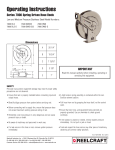
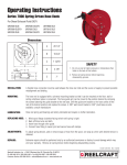
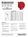
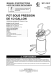
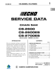
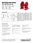
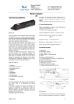
Operating Instructions
Series 7000 Spring Driven Hose Reels
Low, Medium and High Pressure Model Numbers:
7600 OLP
7640 OLP
7650 OLP
7607 OLP
7670 OLP
7800 OLP
7830 OLP
7840 OLP
7850 OLP
7850 OLP121
7850 OLPSW57
7900 OLP
7925 OLP
7600 OMP
7630 OMP
7640 OMP
7650 OMP
7800 OMP
7830 OMP
7840 OMP
7850 OMP
7400 OHP
7440 OHP
7450 OHP
7600 OHP
7640 OHP
7650 OHP
Dimensions
A
20 1/4”
B
19 3/4”
C
7 13/16”
D
3 7/8”
IMPORTANT
E
7”
Read this manual carefully before installing, operating or
servicing this equipment.
SAFETY
Personal injury and/or equipment damage may result if proper safety
precautions are not observed.
•Ensure that reel is properly installed before connecting input and
output hoses.
•A high tension spring assembly is contained within the reel.
Exercise extreme caution.
•Bleed fluid/gas pressure from system before servicing reel.
•Pull hose from reel by grasping the hose itself, not the control
valve.
•Before connecting reel to supply line, ensure that pressure does
not exceed maximum working pressure rating of reel.
•Remember, even low pressure is very dangerous and can cause
personal injury or death.
•Ensure that reel, hose, and equipment being serviced are
properly grounded. Use an ohmmeter to check ground
continuity.
•Be aware of machinery and personnel in work area.
•If reel ceases to unwind or rewind, remove system pressure
immediately. Do not pull or jerk on hose!
•If a leak occurs in the hose or reel, remove system pressure
immediately.
•Treat and respect the hose reel as any other piece of machinery,
observing all common safety practices.
Form# 829-696A Rev: 11/2015
Reelcraft Industries, Inc. • 2842 E Business Hwy 30, Columbia City, IN 46725
Ph: 800-444-3134 / 260-248-8188 • Fax: 800-444-4587 / 260-248-2605
Customer Service: 855-634-9109 • [email protected] • www.reelcraft.com
Series 7000 Spring Driven Hose Reels
INSTALLATION INSTRUCTIONS
MOUNTING
Caution: Unless reel was specified
differently when ordering, maximum
installation height is 16 feet. Do not
exceed this distance.
1. Unpack and inspect reel for damage.
Turn by hand to check for smooth
operation. Check for completeness.
2. Configure reel for top, side or
bottom-wind hose dispensing by
removing nuts (1) securing guide arm
bracket (2). Position guide arm bracket
to desired location, and replace nuts.
Caution: When changing guide arm
positions, the U-bolt must be placed in
the proper location as instructed in
figure A below. The reel can
“latch out” during use if this
instruction is not adhered to.
3. Position reel on floor, wall, or ceiling.
Secure into place using four (customer
supplied) bolts (3).
INSTALLING THE INPUT HOSE(S)
Warning: Ensure that supply line
pressure does not exceed maximum
working pressure rating of reel. Apply
pipe thread sealant to all threads.
Caution: Use flexible hose connection at
input. Do not use rigid plumbing.
1. Connect supply line hose (4) to main
shaft input (5) as indicated in
illustration.
INSTALLING THE OUTPUT HOSE(S)
Warning: Use extreme caution; reel
under tension. Avoid releasing latch
mechanism. Apply pipe thread sealant to
all threads.
1. Manually turn sheave (10) until spring
is tight, back off 3 turns, then latch.
2. Route output hose(s) (11) through
guide arm bracket (2), U-bolts (12),
then through cutout (13) in spool as
indicated in illustration.
3. Connect output hose(s) (11) to swivel
(14) as indicated in illustration.
4. Tighten U-bolts (12).
5. Charge hose(s). Momentarily open
control valve to purge hose(s) of gases.
When fluid appears at control valve,
close valve. With hose(s) fully charged,
release latch and wind output hose(s)
onto reel.
ADJUSTMENTS
Warning: Use extreme caution; reel
under tension. Avoid releasing latch
mechanism. If necessary, adjust spring
tension on reel by adding or removing
wraps of hose from spool, one wrap at a
time, until desired tension is obtained.
Add wraps to increase tension. Remove
wraps to decrease tension.
SERVICE INSTRUCTIONS
User servicing of the reel is limited to
replacing input/output hoses only. Refer
all other repairs to an authorized service
person or directly to Reelcraft. Failure to
do so can result in personal injury and/or
equipment damage and may void the
warranty. Warning: Rewind hose on
reel, then bleed pressure from system
before performing the following procedures.
1. Replace hoses in accordance with
procedures given in “Installation
Instructions” section of this manual.
Caution: When replacing drive spring,
hold the center of the spring down as the
hub is pulled out. If the center is allowed
to raise up, the spring may escape from
it’s container with enough force to cause
injuries.
When disposing of old or broken spring
assemblies, the coils should be welded or
wired together to prevent possible injury
to scrap handling personnel.
2. All mating moving parts are to be
lubricated with Perma Bond or Loctite
anti-seize compound.
Figure A
Page 2
www.reelcraft.com
Series 7000 Spring Driven Hose Reels
Item
Description
#
1 Swivel Assembly
3 90° Ell
4 Sheave Assembly
5 Drive Spring Assembly
6 Spring Arbor Assembly
7 Gasket
8 Spring Case Assembly
10 Main Shaft
11 1 1/4” Snap Ring
12 Base Assembly
13 1/2-13 Set Screw
14 Guide arm with Rollers
15 Hose Bumper Assembly
16 5/16-18 Locknut
17 10-32 x 3/8” Nyloc Nut
18 1/2-20 x 5/8” Hex Nut
19 Latch Spring
21 10-32 Shoulder Screw
22 Latch Pawl Assembly
23 3/8-24 Jam Nut
24 Spring Case Stud
25 U-bolt
26 1/4-20 x 3/8” Locknut
28 Swivel Union
Hose Assembly
Hose I.D. x Length
Reel Inlet Connection
Max. Operating Pressure
Max. Operating Temperature
www.reelcraft.com
#
Req.
1
1
1
1
1
1
1
1
2
1
1
1
1
4
7
1
1
1
1
1
1
1
2
1
7600 OLP
7640 OLP
7650 OLP
7607 OLP
7670 OLP
S600923-1
None
S260011
S260028
S600621
S260069
S260074
602231
300007
S600016
S35-84
S600017
None
300107
S82-15
S280-8
260067-1
S393-2
S600018
S76-106
S260031
3-117440
261650-1
S257-26
None
None
1/2” FPT
500 PSI
210 °F
S600923-1 S600923-1 S600923-1 S600923-1
None
None
None
None
S260011
S260011
S260011
S260011
S260028-1
260028-1
S260028
S260028
S600621
S600621
S600621
S600621
S260069
S260069
S260069
S260069
S260074
S260074
S260074
S260074
602231
602231
602231
602231
300007
300007
300007
300007
S600016
S600016
S600016
S600016
S35-84
S35-84
S35-84
S35-84
S600017
S600017
S600017
S600017
1-HR1004-3 1-HR1004-3
None
1-HR1004-3
300107
300107
300107
300107
S82-15
S82-15
S82-15
S82-15
S280-8
S280-8
S280-8
S280-8
260067-1
260067-1 260067-1 260067-1
S393-2
S393-2
S393-2
S393-2
S600018
S600018
S600018
S600018
S76-106
S76-106
S76-106
S76-106
S260031
S260031
S260031
S260031
3-117440
3-117440 3-117440 3-117440
261650-1
261650-1 261650-1 261650-1
S257-26
S257-26
S257-26
S257-26
601014-40 601017-50
None
601017-70
3/8” x 40’
3/8” x 50’
None
3/8” x 70’
1/2” FPT
1/2” FPT
1/2” FPT
1/2” FPT
300 PSI
300 PSI
500 PSI
300 PSI
150 °F
150 °F
210 °F
150 °F
7800 OLP
7830 OLP
7840 OLP
7850 OLP
S600923-1 S600923-1 S600923-1 S600923-1
None
None
None
None
S260011
S260011
S260011
S260011
S260037
S260037
S260037
S260037
S600621
S600621
S600621
S600621
S260069
S260069
S260069
S260069
S260074
S260074
S260074
S260074
602231
602231
602231
602231
300007
300007
300007
300007
S600016
S600016
S600016
S600016
S35-84
S35-84
S35-84
S35-84
S600017
S600017
S600017
S600017
None
2-HR1004-3 2-HR1004-3 2-HR1004-3
300107
300107
300107
300107
S82-15
S82-15
S82-15
S82-15
S280-8
S280-8
S280-8
S280-8
260067-1 260067-1
260067-1
260067-1
S393-2
S393-2
S393-2
S393-2
S600018
S600018
S600018
S600018
S76-106
S76-106
S76-106
S76-106
S260031
S260031
S260031
S260031
3-117440 3-117440
3-117440
3-117440
261650-1 261650-1
261650-1
261650-1
S257-26
S257-26
S257-26
S257-26
None
601021-30 601019-40 601021-50
None
1/2” x 30’
1/2” x 40’
1/2” x 50’
1/2” FPT
1/2” FPT
1/2” FPT
1/2” FPT
500 PSI
300 PSI
300 PSI
300 PSI
210 °F
150 °F
150 °F
150 °F
Page 3
Series 7000 Spring Driven Hose Reels
7850
7850
Item
#
Description
#
Req. OLP121
OLPSW57
1 Swivel Assembly
1
S600923-1 S600923-1
3 90° Ell
2
None
None
4 Sheave Assembly
1
S260011
S260011
5 Drive Spring Assembly
1
S260037
S260037
6 Spring Arbor Assembly 1
S600621
S600621
7 Gasket
1
S260069
S260069
8 Spring Case Assembly
1
S260074
S260074
10 Main Shaft
1
602231
602231
11 1 1/4” Snap Ring
2
300007
300007
12 Base Assembly
1
600012
600016
13 1/2-13 Set Screw
1
S35-84
S35-84
14 Guide arm with Rollers
1
S600017
S600017
15 Hose Bumper Assembly 1 2-HR1004-3 2-HR1004-3
16 5/16-18 Locknut
4
300107
300107
17 10-32 x 3/8” Nyloc Nut 7
S82-15
S82-15
18 1/2-20 x 5/8” Hex Nut
1
S280-8
S280-8
19 Latch Spring
1
260067-1
260067-1
21 10-32 Shoulder Screw
1
S393-2
S393-2
22 Latch Pawl Assembly
1
S600018
S600018
23 3/8-24 Jam Nut
1
S76-106
S76-106
24 Spring Case Stud
1
S260031
S260031
25 U-bolt
1
3-117440
3-117440
26 1/4-20 x 3/8” Locknut
2
261650-1
261650-1
28 Swivel Union
1
S257-26
S257-26
Hose Assembly
601022-50 S601053-50
Hose I.D. x Length
1/2” x 50’
1/2” x 50’
Reel Inlet Connection
1/2” FPT
3/4” NH
Max. Operating Pressure
300 PSI
300 PSI
Max. Operating Temperature
150 °F
150 °F
Item
Description
#
1 Swivel Assembly
3 90° Ell
4 Sheave Assembly
5 Drive Spring Assembly
6 Spring Arbor Assembly
7 Gasket
8 Spring Case Assembly
10 Main Shaft
11 1 1/4” Snap Ring
12 Base Assembly
13 1/2-13 Set Screw
14 Guide arm with Rollers
15 Hose Bumper Assembly
16 5/16-18 Locknut
17 10-32 x 3/8” Nyloc Nut
18 1/2-20 x 5/8” Hex Nut
19 Latch Spring
21 10-32 Shoulder Screw
22 Latch Pawl Assembly
23 3/8-24 Jam Nut
24 Spring Case Stud
25 U-bolt
26 1/4-20 x 3/8” Locknut
28 Swivel Union
Hose Assembly
Hose I.D. x Length
Reel Inlet Connection
Max. Operating Pressure
Max. Operating Temperature
Page 4
7900 OLP
7925 OLP
7600 OMP
600242
S159-5
S260011
S600023
S600621
S260069
S260074
602231-1
300007
600016
S35-84
S600017
None
300107
S82-15
S280-8
260067-1
S393-2
S600018
S76-106
S260031
5-117440
261650-1
None
None
None
3/4” FPT
500 PSI
210 °F
600242
S159-5
S260011
S600023
S600621
S260069
S260074
602231-1
300007
600016
S35-84
S600017
3-HR1004-3
300107
S82-15
S280-8
260067-1
S393-2
S600018
S76-106
S260031
5-117440
261650-1
None
601026-25
3/4” x 25’
3/4” FPT
250 PSI
150 °F
S600300
None
S260011
S260053
S600621
S260069
S260074
602231
300007
600016
S35-84
S600017
None
300107
S82-15
S280-8
260067-1
S393-2
S600018
S76-106
S260031
3-117440
261650-1
S257-26
None
None
1/2” FPT
3000 PSI
210 °F
7630 OMP
7640 OMP
7650 OMP
S600300
S600300
S600300
None
None
None
S260011
S260011
S260011
S260053
S260053
S260053
S600621
S600621
S600621
S260069
S260069
S260069
S260074
S260074
S260074
602231
602231
602231
300007
300007
300007
600016
600016
600016
S35-84
S35-84
S35-84
S600017
S600017
S600017
1-HR1004-3 1-HR1004-3 1-HR1004-3
300107
300107
300107
S82-15
S82-15
S82-15
S280-8
S280-8
S280-8
260067-1
260067-1
260067-1
S393-2
S393-2
S393-2
S600018
S600018
S600018
S76-106
S76-106
S76-106
S260031
S260031
S260031
3-117440
3-117440
3-117440
261650-1
261650-1
261650-1
S257-26
S257-26
S257-26
3-260043
4-260043
5-260043
3/8” x 30’
3/8” x 40’
3/8” x 50’
1/2” FPT
1/2” FPT
1/2” FPT
2600 PSI
2600 PSI
2600 PSI
210 °F
210 °F
210 °F
7800 OMP
S600300
None
S260011
S260053
S600621
S260069
S260074
602231
300007
600016
S35-84
S600017
None
300107
S82-15
S280-8
260067-1
S393-2
S600018
S76-106
S260031
3-117440
261650-1
S257-26
None
None
1/2” FPT
3250 PSI
210 °F
#
7450 OHP 7600 OHP 7640 OHP 7650 OHP
Req. 7830 OMP 7840 OMP 7850 OMP 7400 OHP 7440 OHP
1
S600300
S600300
S600300
S602110
S602110
S602110
S602110
S602110
S602110
1
None
None
None
None
None
None
None
None
None
1
S260011
S260011
S260011
S600364
S600364
S600364
S260011
S260011
S260011
1
S260053
S260053
S260053
S260053
S260053
S260053
S260053
S260053
S260053
1
S600621
S600621
S600621
S600621
S600621
S600621
S600621
S600621
S600621
1
S260069
S260069
S260069
S260069
S260069
S260069
S260069
S260069
S260069
1
S260074
S260074
S260074
S260074
S260074
S260074
S260074
S260074
S260074
1
602231
602231
602231
602231
602231
602231
602231
602231
602231
2
300007
300007
300007
300007
300007
300007
300007
300007
300007
1
600016
S600016
S600016
S600016
S600016
S600016
S600016
S600016
S600016
1
S35-84
S35-84
S35-84
S35-84
S35-84
S35-84
S35-84
S35-84
S35-84
1
S600017
S600017
S600017
S600017
S600017
S600017
S600017
S600017
S600017
1 2-HR1004-3 2-HR1004-3 2-HR1004-3
None
1-HR1004-3A 1-HR1004-3A
None
1-HR1004-3 1-HR1004-3
4
300107
300107
300107
300107
300107
300107
300107
300107
300107
7
S82-15
S82-15
S82-15
S82-15
S82-15
S82-15
S82-15
S82-15
S82-15
1
S280-8
S280-8
S280-8
S280-8
S280-8
S280-8
S280-8
S280-8
S280-8
1
260067-1
260067-1
260067-1 260067-1 260067-1
260067-1 260067-1 260067-1
260067-1
1
S393-2
S393-2
S393-2
S393-2
S393-2
S393-2
S393-2
S393-2
S393-2
1
S600018
S600018
S600018
S600018
S600018
S600018
S600018
S600018
S600018
1
S76-106
S76-106
S76-106
S76-106
S76-106
S76-106
S76-106
S76-106
S76-106
1
S260031
S260031
S260031
S260031
S260031
S260031
S260031
S260031
S260031
1
3-117440
3-117440
3-117440 3-117440 3-117440
3-117440 3-117440 3-117440
3-117440
2
261650-1
261650-1
261650-1 261650-1 261650-1
261650-1 261650-1 261650-1
261650-1
1
S257-26
S257-26
S257-26
S257-72
S257-72
S257-72
S257-72
S257-72
S257-72
6-260043
7-260043
8-260043
None
8-260044
9-260044
None
4-260044
5-260044
1/2” x 30’
1/2” x 40’
1/2” x 50’
None
1/4” x 40’
1/4” x 50’
None
3/8” x 40’
3/8” x 50’
1/2” FPT
1/2” FPT
1/2” FPT
1/4” FPT
1/4” FPT
1/4” FPT
1/4” FPT
1/4” FPT
1/4” FPT
3250 PSI
3250 PSI
3250 PSI 5000 PSI
5000 PSI
5000 PSI
5000 PSI 4800 PSI
4800 PSI
210 °F
210 °F
210 °F
210 °F
210 °F
210 °F
210 °F
210 °F
210 °F
www.reelcraft.com
Instrucciones de Operacion
Series 7000 Carreteles para Mangueras
Bajo, medio y números de modelo de alta presión:
7600 OLP
7640 OLP
7650 OLP
7607 OLP
7670 OLP
7800 OLP
7830 OLP
7840 OLP
7850 OLP
7850 OLP121
7850 OLPSW57
7900 OLP
7925 OLP
7600 OMP
7630 OMP
7640 OMP
7650 OMP
7800 OMP
7830 OMP
7840 OMP
7850 OMP
7400 OHP
7440 OHP
7450 OHP
7600 OHP
7640 OHP
7650 OHP
Dimensiones
A
20 1/4”
B
19 3/4”
C
7 13/16”
D
3 7/8”
IMPORTANTE
E
7”
Lea este manual detenidamente antes de
instalar, operar o dar servicio a este equipo.
Seguridad
Podrían ocurrir lesiones personales y/o daños en el equipo si no se
siguen las instrucciones de seguridad adecuadas.
• Asegúrese de que el carretel esté instalado apropiadamente
antes de conectar las mangueras de entrada y de salida.
• Hay un ensamblaje de resorte de tensión alta en el interior del
carretel. Sea extremadamente precavido.
• Purgue la presión de fluidos/gases del sistema antes de suministrar servicio al carretel.
• Jale la manguera del carretel sujetando la manguera, y no la
válvula de control.
• Antes de conectar el carretel a la línea de suministro,
asegúrese de que la presión no exceda la clasificación máxima
de la presión operativa del carretel.
• Si el carretel deja de desenrollarse o enrollarse, elimine
inmediatamente la presión del sistema. ¡No jale ni sacuda la
manguera!
• Recuerde que aún la presión baja es muy peligrosa y podría
causar lesiones personales o la muerte.
• Trate y utilice el carretel de manguera como lo haría con
cualquier otra máquina, siguiendo todas las pautas de seguridad generales.
• Esté atento y fíjese si hay maquinaria o
personas en el área de trabajo.
• Si existe una fuga en la manguera o en el carretel, elimine
inmediatamente la presión del sistema.
Page 5
Reelcraft Industries, Inc. • 2842 E Business Hwy 30, Columbia City, IN 46725
Ph: 800-444-3134 / 260-248-8188 • Fax: 800-444-4587 / 260-248-2605
Customer Service: 855-634-9109 • [email protected] • www.reelcraft.com
Form# 829-696A Rev: 11/2015
Series 7000 Carreteles para Mangueras
INSTRUCCIONES DE INSTALACIÓN
Montaje
PRECAUCIÓN: A menos de que el carretel haya sido suministrado con características diferentes al ordenarlo, la altura
máxima de instalación es de 16 pies. No
exceda esta altura.
1. Desempaque e inspeccione si el riel
esta dañado. Girelo con la mano
suave y revise su integridad.
2. Configure el riel por arriba, abajo o
lados, enrrolle el dispensador de la
manguera para remover las tuercas
(1) Asegurando la guia de soporte de
el brazo para escoger el sitio, reemplaze las tuercas.
ATENCIÓN: Al cambiar las posiciones del
brazo guía, el perno en U debe colocarse
en la posición correcta, como se indica
en la figura A. Si no se cumple con esta
instrucción, el carrete puede bloquearse
durante el uso.
3. Posicione el carretel sobre el piso,
pared o techo. Asegurese de instalarlo usando cuatro tornillos (abastesidos al cliente) y (3) tuercas.
INSTALACIÓN DE LA MANGUERA DE
ENTRADA
ADVERTENCIA: Asegurece que la linea
de abastecimiento de presion no exeda el
maximo rango de trabajo de presion de el
carretel. Aplique sellante de roscas para
tuberia. PRECAUCION: Use conecciones
de manguera flexible en la entrada. No
use tuberia rigida.
1. Conecte la linea de abastecimiento de
la manguera (4) a la entrada principal
del canal del eje giratorio (5) como
se indica en la ilustracion.
INSTALACIÓN DE LA SALIDA DE
LA(S) MANGUERA(S)
ADVERTENCIA: Use extrema precaucion;
carretel bajo tension. Aplique sellante de
roscas para tuberia a todas las roscas
estandar.
1. Manualmente gire la rueda exentrica
o riel (10) hasta que el resorte este
apretado, devuelvalo 3 giros y entonces asegurelo.
2. Encamine la(s) salida(s) de la
manguera(s) (11) hasta la guia de
soporte de el brazo (2), tornillos-U
(12) entonces saquelos atravez (13)
del carretel como se indica en la
ilustracion.
3. Conecte la(s) salida(s) de la(s) (11)
a el eje giratorio (14) como se indica
en la ilustracion.
4. Aprite los tornillos-U (12).
5. Cargue las mangueras.
Momentaneamente abra la valvula de
control para purgar la mangueras de
los gases cuando el fluido aparesca
en el control de las valvulas, cierre
la valvula, Con las mangueras total
mente cardas, suelte el seguro y
enrrolle la(s) manguera(s) sobre el
carretel.
AJUSTAMIENTOS
ADVERTENCIA: Use extrema precaucion,
carretel bajo tension. Evite soltar el seguro mecanico. Si es necesario, ajuste el
resorte de tencion de el carretel poiniendo
ó quitando vueltas de la manguera del
carretel una vuelta a la vez hasta que la
tension deseada es obtenida. Adicione
vueltas para incrementar la tension. Quite
vueltas para decrecer la tension.
INSTRUCCIONES DE SERVICIO
El suministro de servicio por parte del
usuario se limita únicamente a reemplazar mangueras de entrada/salida. Remita
cualquier otra reparación a un técnico
de servicio autorizado o directamente a
Reelcraft. El no hacerlo podría resultar
en lesiones personales y/o daños del
equipo que podrían anular la garantía.
Advertencia: Enrolle la manguera en el
carretel, y después purgue la presión del
sistema antes de efectuar los siguientes
procedimientos. Precaución: Elimine
toda la tensión del resorte antes de
desensamblar el carretel de manguera. No
trate de abrir el ensamblaje remachado de
la caja de resorte.
1. Reemplace la manguera de acuerdo
con los procedimientos de la sección
Instrucciones de Instalación de este
manual.
2. Todas las partes móviles correspondientes han sido lubricadas adecuadamente en la fábrica.
Figura A
Page 6
www.reelcraft.com
Series 7000 Carreteles para Mangueras
NO.
ART.
7600 OLP
Descripción
REQ.
NO.
1 Eje giratorio emsamblado
1 S600923-1
3 Codo de 90 grados
1
None
4 Polea ensamblada
1 S260011
5 Resorte ensamblado de propulcion
1 S260028
6 Resorte del arbol
1 S600621
7 Empaque
1 S260069
8 Resorte de la caja ensamblada 1 S260074
10 Columna principal
1
602231
11 1 1/4” Anillo de resorte
2
300007
12 Base ensamblada
1 S600016
13 1/2-13 T ornillo
1
S35-84
14 Guia del brazo con rodillos
1 S600017
15 Manguera del parachoque ensamblada
1
None
16 5/16-18 Contre écrou
4
300107
17 10-32 x 3/8” écrou Nyloc
7
S82-15
18 1/2-20 x 5/8” écrou hexagonal 1
S280-8
19 Ressort de loquet
1 S260067
21 10-32 tornillo de hombro
1
S393-2
22 Assemblage de cliquet
1 S600018
23 3/8-24 contre-écrou
1 S76-106
1 S260031
24 Boulon de boîtier de ressort
25 Tornillo “u”
1 3-117440
26 1/4-20 x 3/8” contre-écrou
2 261650-1
28 Union del eje giratorio
1 S257-26
Manguera del ensamblada
None
Manguera I.D. y Medida
None
Coneccion de Entrada al Carretel
1/2” FPT
Max. Presion de Operacion
500 PSI
Max. Temperatura de Operacion
210 °F
www.reelcraft.com
7640 OLP
7650 OLP 7607 OLP 7670 OLP 7800 OLP 7830 OLP
S600923-1 S600923-1 S600923-1
None
None
None
S260011
S260011 S260011
S260028-1
260028-1 S260028
S600621
S600621 S600621
S260069
S260069 S260069
S260074
S260074 S260074
602231
602231
602231
300007
300007
300007
S600016
S600016 S600016
S35-84
S35-84
S35-84
S600017
S600017 S600017
1-HR1004-3 1-HR1004-3 None
300107
300107
300107
S82-15
S82-15
S82-15
S280-8
S280-8
S280-8
S260067
S260067 S260067
S393-2
S393-2
S393-2
S600018
S600018 S600018
S76-106
S76-106
S76-106
S260031
S260031 S260031
3-117440
3-117440 3-117440
261650-1
261650-1 261650-1
S257-26
S257-26
S257-26
601014-40 601017-50
None
3/8” x 40’
3/8” x 50’
None
1/2” FPT
1/2” FPT 1/2” FPT
300 PSI
300 PSI
500 PSI
150 °F
150 °F
210 °F
S600923-1
None
S260011
S260028
S600621
S260069
S260074
602231
300007
S600016
S35-84
S600017
1-HR1004-3
300107
S82-15
S280-8
S260067
S393-2
S600018
S76-106
S260031
3-117440
261650-1
S257-26
601017-70
3/8” x 70’
1/2” FPT
300 PSI
150 °F
S600923-1
None
S260011
S260037
S600621
S260069
S260074
602231
300007
S600016
S35-84
S600017
None
300107
S82-15
S280-8
S260067
S393-2
S600018
S76-106
S260031
3-117440
261650-1
S257-26
None
None
1/2” FPT
500 PSI
210 °F
7840 OLP
7850 OLP
S600923-1 S600923-1 S600923-1
None
None
None
S260011
S260011
S260011
S260037
S260037
S260037
S600621
S600621
S600621
S260069
S260069
S260069
S260074
S260074
S260074
602231
602231
602231
300007
300007
300007
S600016
S600016
S600016
S35-84
S35-84
S35-84
S600017
S600017
S600017
2-HR1004-3 2-HR1004-3 2-HR1004-3
300107
300107
300107
S82-15
S82-15
S82-15
S280-8
S280-8
S280-8
S260067
S260067
S260067
S393-2
S393-2
S393-2
S600018
S600018
S600018
S76-106
S76-106
S76-106
S260031
S260031
S260031
3-117440
3-117440
3-117440
261650-1
261650-1
261650-1
S257-26
S257-26
S257-26
601021-30 601019-40 601021-50
1/2” x 30’
1/2” x 40’
1/2” x 50’
1/2” FPT
1/2” FPT
1/2” FPT
300 PSI
300 PSI
300 PSI
150 °F
150 °F
150 °F
Page 7
Series 7000 Carreteles para Mangueras
ART.
NO.
7850
7850
Descripción
OLPSW57
NO.
REQ. OLP121
1 Eje giratorio emsamblado
1
S600923-1 S600923-1
3 Codo de 90 grados
1
Ninguno
Ninguno
4 Polea ensamblada
1
S260011
S260011
ensamblado de
5 Resorte
1
S260037
S260037
propulcion
6 Resorte del arbol
1
S600621
S600621
7 Empaque
1
S260069
S260069
8 Resorte de la caja ensamblada
1
S260074
S260074
10 Columna principal
1
602231
602231
11 1 1/4” Anillo de resorte
2
300007
300007
12 Base ensamblada
1
600012
600016
13 1/2-13 T ornillo
1
S35-84
S35-84
14 Guia del brazo con rodillos
1
S600017
S600017
del parachoque
15 Manguera
1
2-HR1004-3 2-HR1004-3
ensamblada
16 5/16-18 Contre écrou
4
300107
300107
17 10-32 x 3/8” écrou Nyloc
7
S82-15
S82-15
18 1/2-20 x 5/8” écrou hexagonal
1
S280-8
S280-8
19 Ressort de loquet
1
260067-1
260067-1
21 10-32 tornillo de hombro
1
S393-2
S393-2
22 Assemblage de cliquet
1
S600018
S600018
23 3/8-24 contre-écrou
1
S76-106
S76-106
24 Boulon de boîtier de ressort
1
S260031
S260031
25 Tornillo “u”
1
3-117440
3-117440
26 1/4-20 x 3/8” contre-écrou
2
261650-1
261650-1
28 Union del eje giratorio
1
S257-26
S257-26
Manguera del ensamblada
601022-50 S601053-50
Manguera I.D. y Medida
1/2” x 50’
1/2” x 50’
Coneccion de Entrada al Carretel
1/2” FPT
3/4” NH
Max. Presion de Operacion
300 PSI
300 PSI
Max. Temperatura de Operacion
150 °F
150 °F
7900 OLP
7925 OLP
600242
S159-5
S260011
600242
S159-5
S260011
7600 OMP 7630 OMP 7640 OMP 7650 OMP 7800 OMP
S600300
Ninguno
S260011
S600300
Ninguno
S260011
S600300
Ninguno
S260011
S600300
Ninguno
S260011
S600300
Ninguno
S260011
S600023
S600023
S260053
S260053
S260053
S260053
S260053
S600621
S260069
S260074
602231-1
300007
600016
S35-84
S600017
S600621
S260069
S260074
602231-1
300007
600016
S35-84
S600017
S600621
S260069
S260074
602231
300007
600016
S35-84
S600017
S600621
S260069
S260074
602231
300007
600016
S35-84
S600017
S600621
S260069
S260074
602231
300007
600016
S35-84
S600017
S600621
S260069
S260074
602231
300007
600016
S35-84
S600017
S600621
S260069
S260074
602231
300007
600016
S35-84
S600017
Ninguno
3-HR1004-3
Ninguno
300107
S82-15
S280-8
260067-1
S393-2
S600018
S76-106
S260031
5-117440
261650-1
Ninguno
Ninguno
Ninguno
3/4” FPT
500 PSI
210 °F
300107
S82-15
S280-8
260067-1
S393-2
S600018
S76-106
S260031
5-117440
261650-1
Ninguno
601026-25
3/4” x 25’
3/4” FPT
250 PSI
150 °F
300107
S82-15
S280-8
260067-1
S393-2
S600018
S76-106
S260031
3-117440
261650-1
S257-26
Ninguno
Ninguno
1/2” FPT
3000 PSI
210 °F
1-HR1004-3 1-HR1004-3 1-HR1004-3
300107
S82-15
S280-8
260067-1
S393-2
S600018
S76-106
S260031
3-117440
261650-1
S257-26
3-260043
3/8” x 30’
1/2” FPT
2600 PSI
210 °F
300107
S82-15
S280-8
260067-1
S393-2
S600018
S76-106
S260031
3-117440
261650-1
S257-26
4-260043
3/8” x 40’
1/2” FPT
2600 PSI
210 °F
300107
S82-15
S280-8
260067-1
S393-2
S600018
S76-106
S260031
3-117440
261650-1
S257-26
5-260043
3/8” x 50’
1/2” FPT
2600 PSI
210 °F
Ninguno
300107
S82-15
S280-8
260067-1
S393-2
S600018
S76-106
S260031
3-117440
261650-1
S257-26
Ninguno
Ninguno
1/2” FPT
3250 PSI
210 °F
ART.
NO.
Descripción
7830 OMP 7840 OMP 7850 OMP 7400 OHP 7440 OHP
7450 OHP 7600 OHP 7640 OHP 7650 OHP
NO.
REQ.
1 Eje giratorio emsamblado
1
S600300
S600300
S600300
S602110
S602110
S602110
S602110
S602110
S602110
3 Codo de 90 grados
1
Ninguno
Ninguno
Ninguno
Ninguno
Ninguno
Ninguno
Ninguno
Ninguno
Ninguno
4 Polea ensamblada
1
S260011
S260011
S260011
S600364
S600364
S600364
S260011
S260011
S260011
ensamblado de
5 Resorte
1
S260053
S260053
S260053
S260053
S260053
S260053
S260053
S260053
S260053
propulcion
6 Resorte del arbol
1
S600621
S600621
S600621
S600621
S600621
S600621
S600621
S600621
S600621
7 Empaque
1
S260069
S260069
S260069
S260069
S260069
S260069
S260069
S260069
S260069
8 Resorte de la caja ensamblada 1
S260074
S260074
S260074
S260074
S260074
S260074
S260074
S260074
S260074
10 Columna principal
1
602231
602231
602231
602231
602231
602231
602231
602231
602231
11 1 1/4” Anillo de resorte
2
300007
300007
300007
300007
300007
300007
300007
300007
300007
S600016
12 Base ensamblada
1
600016
S600016
S600016
S600016
S600016
S600016
S600016
S600016
13 1/2-13 T ornillo
1
S35-84
S35-84
S35-84
S35-84
S35-84
S35-84
S35-84
S35-84
S35-84
14 Guia del brazo con rodillos
1
S600017
S600017
S600017
S600017
S600017
S600017
S600017
S600017
S600017
del parachoque
15 Manguera
1
2-HR1004-3 2-HR1004-3 2-HR1004-3 Ninguno 1-HR1004-3A 1-HR1004-3A Ninguno 1-HR1004-3 1-HR1004-3
ensamblada
16 5/16-18 Contre écrou
4
300107
300107
300107
300107
300107
300107
300107
300107
300107
17 10-32 x 3/8” écrou Nyloc
7
S82-15
S82-15
S82-15
S82-15
S82-15
S82-15
S82-15
S82-15
S82-15
18 1/2-20 x 5/8” écrou hexagonal 1
S280-8
S280-8
S280-8
S280-8
S280-8
S280-8
S280-8
S280-8
S280-8
19 Ressort de loquet
1
S260067
S260067
S260067
S260067
S260067
S260067
S260067
S260067
S260067
21 10-32 tornillo de hombro
1
S393-2
S393-2
S393-2
S393-2
S393-2
S393-2
S393-2
S393-2
S393-2
22 Assemblage de cliquet
1
S600018
S600018
S600018
S600018
S600018
S600018
S600018
S600018
S600018
23 3/8-24 contre-écrou
1
S76-106
S76-106
S76-106
S76-106
S76-106
S76-106
S76-106
S76-106
S76-106
24 Boulon de boîtier de ressort
1
S260031
S260031
S260031
S260031
S260031
S260031
S260031
S260031
S260031
25 Tornillo “u”
1
3-117440
3-117440
3-117440
3-117440
3-117440
3-117440
3-117440
3-117440
3-117440
26 1/4-20 x 3/8” contre-écrou
2
261650-1
261650-1
261650-1
261650-1
261650-1
261650-1
261650-1
261650-1
261650-1
28 Union del eje giratorio
1
S257-26
S257-26
S257-26
S257-72
S257-72
S257-72
S257-72
S257-72
S257-72
Manguera del ensamblada
6-260043
7-260043
8-260043
Ninguno
8-260044
9-260044
Ninguno
4-260044
5-260044
Manguera I.D. y Medida
1/2” x 30’
1/2” x 40’
1/2” x 50’
Ninguno
1/4” x 40’
1/4” x 50’
Ninguno
3/8” x 40’
3/8” x 50’
Coneccion de Entrada al Carretel
1/2” FPT
1/2” FPT
1/2” FPT
1/4” FPT
1/4” FPT
1/4” FPT
1/4” FPT
1/4” FPT
1/4” FPT
Max. Presion de Operacion
3250 PSI
3250 PSI
3250 PSI
5000 PSI
5000 PSI
5000 PSI
5000 PSI
4800 PSI
4800 PSI
Max. Temperatura de Operacion
210 °F
210 °F
210 °F
210 °F
210 °F
210 °F
210 °F
210 °F
210 °F
Page 8
www.reelcraft.com
Instructions D’Opération
Série 7000 Enrouleurs de Tuyau
Bas, milieu et numéros de type à haute pression:
7600 OLP
7640 OLP
7650 OLP
7607 OLP
7670 OLP
7800 OLP
7830 OLP
7840 OLP
7850 OLP
7850 OLP121
7850 OLPSW57
7900 OLP
7925 OLP
7600 OMP
7630 OMP
7640 OMP
7650 OMP
7800 OMP
7830 OMP
7840 OMP
7850 OMP
7400 OHP
7440 OHP
7450 OHP
7600 OHP
7640 OHP
7650 OHP
Dimensions
A
20 1/4”
B
19 3/4”
C
7 13/16”
D
3 7/8”
IMPORTANT
E
7”
Lisez ce manuel soigneusement avant d’installer, actionner,
ou entretenir cet èquipment.
Sécurité
Podrían ocurrir lesiones personales y/o daños en el equipo si no se
siguen las instrucciones de seguridad adecuadas.
• Assurez-vous que l’enrouleur est correctement installé avant de
raccorder les tuyaux d’entrée et de sortie.
• Si une fuite apparaît dans le tuyau ou l’enrouleur, décompressez
le système immédiatement.
• Evacuez tout liquide/gaz sous pression du système avant
d’entreprendre l’entretien de l’enrouleur.
• L’enrouleur comporte un assemblage à ressort de haute tension.
Observez la plus grande prudence.
• Avant de raccorder l’enrouleur à la ligne d’alimentation, assurezvous que la pression n’excède pas la pression de fonctionnement
nominale maximum de l’enrouleur.
• Sortez le tuyau de l’enrouleur en tirant sur le tuyau lui-même,
pas sur l’embout.
• Souvenez-vous, même les pressions basses sont dangereuses et
peuvent provoquer des blessures ou la mort.
• Ayez conscience des machines et des personnes se trouvant
dans la zone de travail.
Page 9
Reelcraft Industries, Inc. • 2842 E Business Hwy 30, Columbia City, IN 46725
Ph: 800-444-3134 / 260-248-8188 • Fax: 800-444-4587 / 260-248-2605
Customer Service: 855-634-9109 • [email protected] • www.reelcraft.com
• Si l’enrouleur arrête d’enrouler ou de dérouler, décompressez le
système immédiatement. Ne pas tirer ou secouer le tuyau !
• Comme avec toute autre machine, traitez l’enrouleur de tuyau
avec respect, en observant les consignes de sécurité habituelles.
Form# 829-696A Rev: 11/2015
Série 7000 Enrouleurs de Tuyau
CONSIGNES D’INSTALLATION
MONTAMIENTO
AVERTISSMENT: Sauf enrouleur a été
spécifié différemment lors de la commande, au maximum hauteur d’installation
est de 16 pieds. Ne pas dépasser cette
distance.
1. Déballez l’enrouleur et inspectez-le
pour déceler le dommage. Faites
tournez à la main pour vérifier le bon
fonctionnement. Vérifiez l’enrouleur
pour voir s’il est complet.
2. Agencez l’enrouleur en prévision
d’une sortie laterale, par le haut, ou
par le bas en enlevantles écrous qui
correspondent au support. Fixez le
support guide la position désirée, et
remplacez les écrous.
3. Positionnez l’enrouleur au sol, au
mur, ou au plafond. Fixez-le solidement en utilisant 4 boulons (fournis
par le client).
INSTALLATION DES TUYAUX
D’ENTRÉS
MIS EN GARDE: Assurez-vous que la
pression du tuyau d’alimentation ne
dépasse pas la pression maximum qui
est specifié pour l’enrouleur. Appliquez
du materiau d’étanchiété pour les filets de
tuyau à tous les filets uniquement sur les
enrouleurs. AVERTISSMENT: Utilisez un
raccord flexible à l’entré. N’utilisez pas les
tuyaux rigides.
1. Connectez la ligne d’alimentation (4)
à la manche d’entré principale (5)
comme indiqué.
INSTALLATION DES TUYAUX DE
SORTIES
MIS EN GARDE: Faites attention; enrouleur sous tension! Évitez de lâcher le
mécanisme d’accrochage. Appliquez du
matériau d’étanchéité pour les filets du
tuyau à tous les filets uniquement sur les
enrouleurs.
1. Tournez à la main la poulie (10)
jusqu’au ressort est tendu, puistournez-la 3 tours à la sense opposite, puis fermez au loquet.
2. Guidez le(s) tuyau(x) (11) à travers le
support guide, les boulons en U (12),
et puis à travers le trou (13) dans
l’entrouleur comme indiqué.
3. Connectez le(s) tuyau(x) (11) au raccord tounant (14) comme indiqué.
4. Serrez bien le boulons en U.
5. Chargez le(s) tuyau(x). Ouvrez
momentanément la vanne de régulation pour évacuer le(s) tuyau(x) des
gaz. Quand du fluide arrive à la vanne
de régulation, fermez-la. Lorsque
le(s) tuyau(x) sont completement
chargé(s), relâchez le mécanisme
d’accorchage et enroulez le(s)
tuyau(x) de sortie sur l’enrouleur.
RÉGLAGES
MISE EN GARDE: Faites attention;
enrouleur sous tension. Évitez de relâcher
le mécanisme d’accrochage. Au besoin,
réglez la tension du ressort l’enrouleur en
ajoutant ou en enlevant un tour de câble
à la fois jusqu’à l’obtention de la tension
désirée. Ajoutez un tour de câble pour
augmenter la tension. Enlevez un
tour pour l’effet contraire.
DIRECTIVES DE MAINTENANCE
La maintenance de l’enrouleur par
l’utilisateur est limitée à la remplacement
des tuyaux d’entré et de sortie. Signalez
tout autre problème seulement à une
personne autorisée ou directement à
Reelcraft. Inobservation de le faire peut
résulter en blessure personnel et/ou
le dommage d’équipment. En plus, la
garantie peut être annulée. MISE EN
GARDE: Rebobinez le tuyau à l’enrouleur,
et puis évacuez la pression du système
avant de faire ce qui suit.
1. Remplacez les tuyaux comme
décrivé au paragraphe “Instructions
d’Installation” qui se trouve dans ce
manuel.
AVERTISSMENT: Quand vous remplacez
le ressort de mouvement, maintenez-le
bien en place lorsque le moyeu est enlevé.
Si le centre du ressort peut se lever, il
peut échapper de son conteneur avec
assez de force de causer des blessures.
En jetant de vieux assemblages ou des
assemblages cassés, les câbles doivent
être soudés ensemble ou fixés ensemble
pour éviter des blessures possibles aux
ferrailleurs.
1. Toutes les pièces qui se touchent en
mouvant doivent être lubrifiées avec
du Perma Bond ou du Loctite (composé qui empêche le grippage).
Figure A
Page 10
www.reelcraft.com
Série 7000 Enrouleurs de Tuyau
ART
N°
DÉSCRIPTION
N°.
REQ. 7600 OLP
1 Assemblage de pivot
1 S600923-1
3 Coude à 90°
1
None
4 Assemblage de poulie
1
S260011
de ressort de mouve5 Assemblage
1
S260028
ment
6 Mandrin de ressort
1
S600621
7 Joint d’étanchéité
1
S260069
8 Assemblge de boîtier de ressort
1
S260074
10 Arbre principal
1
602231
11 1 1/4” dispositif de retenue
2
300007
12 Assemblage de base
1
S600016
13 1/2-13 vis sans tête
1
S35-84
14 Assemblage de guide
1
S600017
15 Assemblage d’arrêt de câble
1
None
16 5/16-18 contre écrou
4
300107
17 10-32 x 3/8” écrou Nyloc
7
S82-15
18 1/2-20 x 5/8” écrou hexagonal
1
S280-8
19 Ressort de loquet
1
S260067
21 10-32 vis à épaulement
1
S393-2
22 Assemblage de cliquet
1
S600018
23 3/8-24 contre-écrou
1
S76-106
24 Boulon de boîtier de ressort
1
S260031
25 Boulon en U
1
3-117440
26 1/4-20 x 3/8” contre-écrou
2
261650-1
28 Union de pivot
1
S257-26
Assemblage de tuyau
None
Longeur et Diamètre Intérieur du Tuyau
None
Raccord d’entré d’enrouleur
1/2” FPT
Pression d’opération maximum
500 PSI
Température d’opération maximum
210 °F
www.reelcraft.com
7640 OLP
7650 OLP
7607 OLP
7670 OLP
7800 OLP
7830 OLP
7840 OLP
7850 OLP
S600923-1
None
S260011
S600923-1
None
S260011
S600923-1
None
S260011
S600923-1
None
S260011
S600923-1
None
S260011
S600923-1
None
S260011
S600923-1
None
S260011
S600923-1
None
S260011
S260028-1
260028-1
S260028
S260028
S260037
S260037
S260037
S260037
S600621
S260069
S260074
602231
300007
S600016
S35-84
S600017
1-HR1004-3
300107
S82-15
S280-8
S260067
S393-2
S600018
S76-106
S260031
3-117440
261650-1
S257-26
601014-40
3/8” x 40’
1/2” FPT
300 PSI
150 °F
S600621
S260069
S260074
602231
300007
S600016
S35-84
S600017
1-HR1004-3
300107
S82-15
S280-8
S260067
S393-2
S600018
S76-106
S260031
3-117440
261650-1
S257-26
601017-50
3/8” x 50’
1/2” FPT
300 PSI
150 °F
S600621
S260069
S260074
602231
300007
S600016
S35-84
S600017
None
300107
S82-15
S280-8
S260067
S393-2
S600018
S76-106
S260031
3-117440
261650-1
S257-26
None
None
1/2” FPT
500 PSI
210 °F
S600621
S260069
S260074
602231
300007
S600016
S35-84
S600017
1-HR1004-3
300107
S82-15
S280-8
S260067
S393-2
S600018
S76-106
S260031
3-117440
261650-1
S257-26
601017-70
3/8” x 70’
1/2” FPT
300 PSI
150 °F
S600621
S260069
S260074
602231
300007
S600016
S35-84
S600017
None
300107
S82-15
S280-8
S260067
S393-2
S600018
S76-106
S260031
3-117440
261650-1
S257-26
None
None
1/2” FPT
500 PSI
210 °F
S600621
S260069
S260074
602231
300007
S600016
S35-84
S600017
2-HR1004-3
300107
S82-15
S280-8
S260067
S393-2
S600018
S76-106
S260031
3-117440
261650-1
S257-26
601021-30
1/2” x 30’
1/2” FPT
300 PSI
150 °F
S600621
S260069
S260074
602231
300007
S600016
S35-84
S600017
2-HR1004-3
300107
S82-15
S280-8
S260067
S393-2
S600018
S76-106
S260031
3-117440
261650-1
S257-26
601019-40
1/2” x 40’
1/2” FPT
300 PSI
150 °F
S600621
S260069
S260074
602231
300007
S600016
S35-84
S600017
2-HR1004-3
300107
S82-15
S280-8
S260067
S393-2
S600018
S76-106
S260031
3-117440
261650-1
S257-26
601021-50
1/2” x 50’
1/2” FPT
300 PSI
150 °F
Page 11
Série 7000 Enrouleurs de Tuyau
ART
N°
DÉSCRIPTION
N°.
REQ. 7850 OLP121
1 Assemblage de pivot
1
S600923-1
3 Coude à 90°
1
None
4 Assemblage de poulie
1
S260011
de ressort de
5 Assemblage
1
S260037
mouvement
6 Mandrin de ressort
1
S600621
7 Joint d’étanchéité
1
S260069
Assemblge
de
boîtier
de
8 ressort
1
S260074
10 Arbre principal
1
602231
11 1 1/4” dispositif de retenue
2
300007
12 Assemblage de base
1
600012
13 1/2-13 vis sans tête
1
S35-84
14 Assemblage de guide
1
S600017
15 Assemblage d’arrêt de câble
1
2-HR1004-3
16 5/16-18 contre écrou
4
300107
17 10-32 x 3/8” écrou Nyloc
7
S82-15
18 1/2-20 x 5/8” écrou hexagonal 1
S280-8
19 Ressort de loquet
1
260067-1
21 10-32 vis à épaulement
1
S393-2
22 Assemblage de cliquet
1
S600018
23 3/8-24 contre-écrou
1
S76-106
24 Boulon de boîtier de ressort
1
S260031
25 Boulon en U
1
3-117440
26 1/4-20 x 3/8” contre-écrou
2
261650-1
28 Union de pivot
1
S257-26
Assemblage de tuyau
601022-50
Longeur et Diamètre Intérieur du Tuyau
1/2” x 50’
Raccord d’entré d’enrouleur
1/2” FPT
Pression d’opération maximum
300 PSI
Température d’opération maximum
150 °F
ART
N°
DÉSCRIPTION
N°.
REQ. 7830 OMP
1 Assemblage de pivot
1
S600300
3 Coude à 90°
1
Aucun
4 Assemblage de poulie
1
S260011
de ressort de
5 Assemblage
1
S260053
mouvement
6 Mandrin de ressort
1
S600621
7 Joint d’étanchéité
1
S260069
de boîtier de
8 Assemblge
1
S260074
ressort
10 Arbre principal
1
602231
11 1 1/4” dispositif de retenue
2
300007
12 Assemblage de base
1
600016
13 1/2-13 vis sans tête
1
S35-84
14 Assemblage de guide
1
S600017
15 Assemblage d’arrêt de câble
1
2-HR1004-3
16 5/16-18 contre écrou
4
300107
17 10-32 x 3/8” écrou Nyloc
7
S82-15
18 1/2-20 x 5/8” écrou hexagonal 1
S280-8
19 Ressort de loquet
1
S260067
21 10-32 vis à épaulement
1
S393-2
22 Assemblage de cliquet
1
S600018
23 3/8-24 contre-écrou
1
S76-106
24 Boulon de boîtier de ressort
1
S260031
25 Boulon en U
1
3-117440
26 1/4-20 x 3/8” contre-écrou
2
261650-1
28 Union de pivot
1
S257-26
Assemblage de tuyau
6-260043
Longeur et Diamètre Intérieur du Tuyau
1/2” x 30’
Raccord d’entré d’enrouleur
1/2” FPT
Pression d’opération maximum
3250 PSI
Température d’opération maximum
210 °F
Page 12
7850
OLPSW57
S600923-1
None
S260011
7900 OLP
7925 OLP
7600 OMP
7630 OMP
7640 OMP
7650 OMP
7800 OMP
600242
S159-5
S260011
600242
S159-5
S260011
S600300
None
S260011
S600300
None
S260011
S600300
None
S260011
S600300
None
S260011
S600300
None
S260011
S260037
S600023
S600023
S260053
S260053
S260053
S260053
S260053
S600621
S260069
S600621
S260069
S600621
S260069
S600621
S260069
S600621
S260069
S600621
S260069
S600621
S260069
S600621
S260069
S260074
S260074
S260074
S260074
S260074
S260074
S260074
S260074
602231
300007
600016
S35-84
S600017
2-HR1004-3
300107
S82-15
S280-8
260067-1
S393-2
S600018
S76-106
S260031
3-117440
261650-1
S257-26
S601053-50
1/2” x 50’
3/4” NH
300 PSI
150 °F
602231-1
300007
600016
S35-84
S600017
None
300107
S82-15
S280-8
260067-1
S393-2
S600018
S76-106
S260031
5-117440
261650-1
None
None
None
3/4” FPT
500 PSI
210 °F
602231-1
300007
600016
S35-84
S600017
3-HR1004-3
300107
S82-15
S280-8
260067-1
S393-2
S600018
S76-106
S260031
5-117440
261650-1
None
601026-25
3/4” x 25’
3/4” FPT
250 PSI
150 °F
602231
300007
600016
S35-84
S600017
None
300107
S82-15
S280-8
260067-1
S393-2
S600018
S76-106
S260031
3-117440
261650-1
S257-26
None
None
1/2” FPT
3000 PSI
210 °F
602231
300007
600016
S35-84
S600017
1-HR1004-3
300107
S82-15
S280-8
260067-1
S393-2
S600018
S76-106
S260031
3-117440
261650-1
S257-26
3-260043
3/8” x 30’
1/2” FPT
2600 PSI
210 °F
602231
300007
600016
S35-84
S600017
1-HR1004-3
300107
S82-15
S280-8
260067-1
S393-2
S600018
S76-106
S260031
3-117440
261650-1
S257-26
4-260043
3/8” x 40’
1/2” FPT
2600 PSI
210 °F
602231
300007
600016
S35-84
S600017
1-HR1004-3
300107
S82-15
S280-8
260067-1
S393-2
S600018
S76-106
S260031
3-117440
261650-1
S257-26
5-260043
3/8” x 50’
1/2” FPT
2600 PSI
210 °F
602231
300007
600016
S35-84
S600017
None
300107
S82-15
S280-8
260067-1
S393-2
S600018
S76-106
S260031
3-117440
261650-1
S257-26
None
None
1/2” FPT
3250 PSI
210 °F
7840 OMP
7850 OMP
7400 OHP
7440 OHP
7450 OHP
7600 OHP
7640 OHP
7650 OHP
S600300
Aucun
S260011
S600300
Aucun
S260011
S602110
Aucun
S600364
S602110
Aucun
S600364
S602110
Aucun
S600364
S602110
Aucun
S260011
S602110
Aucun
S260011
S602110
Aucun
S260011
S260053
S260053
S260053
S260053
S260053
S260053
S260053
S260053
S600621
S260069
S600621
S260069
S600621
S260069
S600621
S260069
S600621
S260069
S600621
S260069
S600621
S260069
S600621
S260069
S260074
S260074
S260074
S260074
S260074
S260074
S260074
S260074
602231
300007
S600016
S35-84
S600017
2-HR1004-3
300107
S82-15
S280-8
S260067
S393-2
S600018
S76-106
S260031
3-117440
261650-1
S257-26
7-260043
1/2” x 40’
1/2” FPT
3250 PSI
210 °F
602231
300007
S600016
S35-84
S600017
2-HR1004-3
300107
S82-15
S280-8
S260067
S393-2
S600018
S76-106
S260031
3-117440
261650-1
S257-26
8-260043
1/2” x 50’
1/2” FPT
3250 PSI
210 °F
602231
300007
S600016
S35-84
S600017
Aucun
300107
S82-15
S280-8
S260067
S393-2
S600018
S76-106
S260031
3-117440
261650-1
S257-72
Aucun
Aucun
1/4” FPT
5000 PSI
210 °F
602231
300007
S600016
S35-84
S600017
Aucun
300107
S82-15
S280-8
S260067
S393-2
S600018
S76-106
S260031
3-117440
261650-1
S257-72
Aucun
Aucun
1/4” FPT
5000 PSI
210 °F
602231
300007
S600016
S35-84
S600017
1-HR1004-3
300107
S82-15
S280-8
S260067
S393-2
S600018
S76-106
S260031
3-117440
261650-1
S257-72
4-260044
3/8” x 40’
1/4” FPT
4800 PSI
210 °F
602231
300007
S600016
S35-84
S600017
1-HR1004-3
300107
S82-15
S280-8
S260067
S393-2
S600018
S76-106
S260031
3-117440
261650-1
S257-72
5-260044
3/8” x 50’
1/4” FPT
4800 PSI
210 °F
602231
602231
300007
300007
S600016
S600016
S35-84
S35-84
S600017
S600017
1-HR1004-3A 1-HR1004-3A
300107
300107
S82-15
S82-15
S280-8
S280-8
S260067
S260067
S393-2
S393-2
S600018
S600018
S76-106
S76-106
S260031
S260031
3-117440
3-117440
261650-1
261650-1
S257-72
S257-72
8-260044
9-260044
1/4” x 40’
1/4” x 50’
1/4” FPT
1/4” FPT
5000 PSI
5000 PSI
210 °F
210 °F
www.reelcraft.com