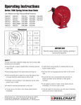
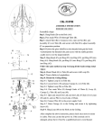
1
Ltd.
10090 Zagreb, Medarska 69
tel. +38549222900, fax +38549426450
www.tepex.hr
e-mail: [email protected]
USER MANUAL FOR EXPLOSION PROTECTED
FLUORESCENT LIGHTING FITTING
TYPE PSF 218 - .
Doc.No: TEPEx.RS.018
Rev : 1
Date: 10.02.2009.
PURPOSE
Explosion proof fluorescent lighting fitting type PSF 218-. is intended for use in industry areas:
- in areas endangered by flammable and explosive mixtures of gases and air, fumes of flammable liquids and air, or various combinations between the two, in danger zones
1,2 in ordinance with standards IEC 60079-10/02.
TYPE OF PROTECTION
Explosion protection is achived by the use of requirements of the protection types: " Ex d flameproof enclosure" in accordance with EN 50018:2001, "Ex e increased safety"
in accordance with EN 50019:2001and "General requirements" in accordance with EN 50014:1997.
Apparatus category: II 2G
Marking of explosion-protection:
- EEx de IIC T6
ambient temperature -20°C<Ta<+40°C
- EEx de IIC T5
ambient temperature -20°C<Ta<+50°C
Type test certificate: Ex Agencija - HREx T05.003
Degree of protection (IP Code): IP 56 in accordance with EN 60529+A1, category 1 - type PSF 218-1
Degree of protection (IP Code): IP 66 in accordance with EN 60529+A1, category 1 - type PSF 218-2
Insulation class : I (protective earthing) in accordance with EN 61140
Electromagnetic compatibility: in accordance with the Directive 89/336 EEC, EN 55015, EN 61547
DESIGN
Casting is made from AlSi10Mg alloy (type PSF218-2, picture 1.) or polyester with glass fibres (type PSF218-1, picture 2.), with silicone gasket, closed with cover made of
UV-stable polycarbonate and secured with clamps with blockade switch to prevent uncontroled opening. Inside are installed: reflector with Ex lampholders and fluorescent
lights, Ex electronic ballast, Ex connecting clamps, and wireing cables.
810
±1
808
200
140
148
±1
188
±1
70
400
800
606
±1
Picture 1.
Picture 2.
TECHNICAL DATA
Rated voltage: 230 V, 50 Hz
Working voltage: 220 - 240 V ± 10%, 50/60 Hz
Light source: 2 x 18 W fluorescent tube T8 (ø26 mm), lampholder G13
Rated power: 37 W
Power factor: λ = 0,95
THD (total harmonic distorsion): < 10 %
Energy efficient: EEI=A1
Fluorescent tube ignition: Instant start with controlled power
Protection from overvoltage: 300V / 5 min
Protection from working without fluorescent tubes
Disconnection of non-working fluorescent tube ( «end of live» effect )
Protection from uptemperature with turning off after reset of power supply with automatic recovery
Lumen output: 2 x 1350 lm (LUMILUX 18 W/840, OSRAM)
Average life expectancy of the fluorescent tubes- average: 12 000 hours (LUMILUX 18 W/840, OSRAM)
Average life expectancy of the electronic ballast: 50 000 hours
Connecting terminals: L1, L2, L3, N, PE - max. 4 mm2 / PE, IP - max. 2 x 6mm2 – solid, stranded
Wiring: 5 x 2,5 mm2 H05SJ-K (L1, L2, L3, N, PE) , 16 A max.
Cable gland & Plug: Cable gland M25x1,5 for cable diameter Ø6-15 mm, and plug M25x1,5 in conformity with EN 50262
Tightening torque: cable gland screw 2,5 Nm; cable gland body and Plug 3,5 Nm
Dimensions: according to pictures 1. and 2.
Weight: ca 7,70 kg
Marking: CE
ASSEMBLY
Assembly and installation of lighting fitting is made according to nacional directive , national regulations and laws, and according to approved rules of technique. Quality of
used materials ensure functionality according to norm, in "normal" industrial enviroment. It is necesarry to prevent operation of fluorescent fitting if it is exposed to extend sun
emission or in another way prevent raise of enviromen temperature above allowed. For boundary cases please contact the manufacturer.
By default, with every fitting, two screws M8 DIN 580 for pendant fitting montage are delivered.
On buyer request, another assemly accessories can be delivered.
Accessories for ceiling mounting
16
Screw M8 DIN 580
3
25
M8
184
O9
10
40
O10
15
240
Accessories for wall mounting or vertical construction with possibility
of fitting rotating angled up to 30°, 45° or 60° regarding to wall
3
10 / 45°
15,3
A
29,3
35,1
29,3
6,4
60
35,1
O
15,3
10 / 45°
A-A
O
6,4
28
20
20,5
40
130
6,4
40
11,6
Accessories for pole or pipe mounting ø38 – ø48 mm
11,6
R21
9
R1
R24
3
O8,5
11
20,5
28
25
40
A
1
ELECTRIC CONNECTION
Connection scheme:
18 W-T8
G 13
G 13
1,5mm 2
crvena
crna 2,5mm 2
crna 1,5mm
2
crna 2,5mm2
crna 2,5mm 2
plava 2,5mm 2
ž-z 2,5mm 2
L3
L1
L2
L2
SMP 05
L1
N
ž-z 1,5mm 2
L3
N
smeđa 1,5mm 2
plava 1,5mm 2
ž-z 1,5mm 2
crvena 1,5mm 2
PE
PE
ž-z 1,5mm 2
crna 1,5mm 2
G 13
18 W-T8
G 13
Clamps deblockade allows fixture opening, and can be done with Allen wrench number 5, turning the blockade switch by 90°counter-clockwise. Deblockade can be done
only on a middle clamp on each side. Than is necesarry to release four screws M4 which tighten inside reflector, and than remove reflector. Now, access to connecting
clamps is allowed. Wireing cable is installed trough cable glands. Special attention must be dedicated to selection of inner gasket sealing ring of Exe gland according to
diameter of connecting cable. Gland screw and gland body with threads must be tightened with torgue regulated by manufacturer. Unused cable introduction must be
closed with plug. The electric connection is performed by linking power supply cable to connecting terminals L1,(L2,L3), N, PE and tightening the screws of connecting
terminals with tightening torque regulated by manufacturer.
It is important to pay attention on maximum number of lighting fittings installed on one automatic installation switch:
Automatic installation switch
Maximum number of ligt. fittings installed
1pB 10A
10
1pC 10A
17
1pB 16A
16
1pC 16A
28
Maximum voltage for dielectric strength insulation resistance test is 1 kV/AC; DC and max. 10mA only between PE and L (L1,L2,L3), and between N and PE.
The closing of the enclosure should be done by a reverse sequence of action.
ASSEMBLGE AND REPLACING THE FLUORESCENT G13 TUBES
The opening of the enclosure is exclusively allowed in a non-voltage state while respecting the warnings on the label. Non-voltage state must be ensured by turning of
power source on main switch. The installing of flurescent G13 tube is done by slightly pushing the left and right side of tube simultaneously into the G13 lampholders.
Than, the G13 tube is need to be turned by 90° in blockade position. In that way, tube is in position which not allow it to fall out. Taking out the tube is done in reverse
sequence of action.
STORAGE AND TRANSPORT
Transport and storage is only allowed in the original packaging, on the way pointed out on the carton box.
CONTROL, MAINTENANCE AND REPAIR
It is necessary to conduct review and maintenance on all parts on which the explosion proof protection depends in accordance to standards IEC 60079-17, general and
individual demands of the manufacturer and the regulations of the user, and especially:
•
that enclosure, the protective cover and the gasket of the cover are completely without a crack or damage
•
that the Exe cable glands, plugs, and connecting terminals are tightened with torque regulated by manufacturer
•
that the protective cover is only cleaning with wet cloth because of danger from electostatic discharge, with adequate use of cleaning detergent, and wash with
water temparature bellow 50°C.
•
That the interval recomended by manufacturer for replacing the G13 tube is respected.
The repair of the fitting is done by the manufacturer or a person legally authorized by the manufacturer, with original parts from the products documentation, and in
accordance to the IEC 60079-19 standards. If the repair is done by a third person, the manufacturer is free of all responsibility from the product, and the declaration of
conformity which is given by the manufacturer becomes insignificant.
Spare parts:
6
1
1.
2.
3.
4.
5.
6.
protective cover, type PSF 218,
gasket, type PSF 218,
electronic ballast with lampholder G13, type SMP 05/4 – 91000 set,
connectin terminal, type SL5,
cable gland M25, type SPU 25,
plug M25, type SPC 25.
2
3
4
5
RESPONSIBILITY AND AUTHORIZATION
Responsibility and authorization are defined by the "Regulation on technical supervision over the electrical stations, installations and equipment intended for usage in
potentially explosive atmospheres" . This Manual represents the most relevant information about the product. Adequate national laws and regulations supplement it. The
person in charge is required to secure its employment in the industrial unit. Every improper usage, as well as every unofficial restructuring, repair or restoration of the
product, release the manufacturer of all responsibilities.
2