1
6200 Grand Pointe Dr., Grand Blanc, MI 48439
Oxygen Sensors
NOTE: It is critical that the Oxygen Sensors are mounted per the
instructions below. The exhaust system MUST be properly sealed –
any leak near the sensors (upstream or downstream) can cause
incorrect operation of the fuel control system. Vehicle performance
and/or driveability may be affected if sensors are not mounted as
recommended or if an exhaust leak exists. Leak check the exhaust
system to ensure adequate sealing (even small leaks can affect fuel
control).
Oxygen sensors should be mounted in the collector area of the
headers or manifolds in a location that allows exhaust from all cylinders to be sampled equally (stock exhaust manifolds include a
mounting boss for the oxygen sensors). Be sure the connectors and
wiring are routed away from high heat areas. The oxygen sensors
should be mounted with the sensor tip pointing between horizontal
and fully downward – do not mount with the tip oriented upward. Weld
in the mounting bosses supplied (7/8” hole) if using headers.
Optional Connections (Not required for operation)
Connections Required for Correct Operation
Connector
Camshaft Position Sensor
Connector
Electronic Throttle Control
Connector
Manifold Absolute Pressure (MAP) Sensor
Connector
Oxygen Sensors (2 total)
Connectors
Knock Sensors (2 total)
Connectors
Ignition Coil Blocks (2 total)
Connectors
Fuel Injectors (8 total)
Connectors
Crankshaft Position Sensor
Connector
Accelerator Pedal Sensor
Connector
Ignition Switch Input (Wire)
Wire
Fuel Pump Control (Wire)
Wire
Engine Grounds (3 total)
Eyelets
Battery Power (Stud at Fuse/Relay Center)
Stud at Fuse/
Relay Center
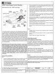
LS Series Crate Engine Control System
ALL INFORMATION WITHIN
ABOVE BORDER TO BE PRINTED
EXACTLY AS SHOWN ON 8.5 x 11
WHITE 16 POUND NON-BOND
RECYCLABLE PAPER.
PRINT ON BOTH SIDES, EXCLUDING TEMPLATES.
TO BE UNITIZED IN ACCORDANCE WITH GMSPO SPECIFICATIONS.
DATE
REVISION
*Engine Oil Pressure Sensor
Connector
Vehicle Speed Sensor
Connector
Optional User Outputs
Bulkhead
Connector
(12-way)
The harness includes a fuse/relay center containing all required
fuses and relays, and also a 12-way bulkhead connector (with
sealed mating connector) which contains outputs that may be
useful to the user (see ‘Bulkhead Connector Outputs’ section
below). The fuse/relay center should be mounted as high in the
engine compartment as possible to avoid unnecessary splash
and road debris. Likewise, keep the 12-way bulkhead connector
and diagnostic link connector (both connect from the fuse/relay
center) as high and protected as possible. The 3 ECM connectors are indexed to connect only in the correct locations. Install
by pressing down firmly until the connector is seated, then pull
the top slider bar down until it snaps and locks into place. The
bar should slide easily and will not move unless the connector is
seated properly, do not use excessive force.
NOTE: A Malfunction Indicator Lamp (MIL) is mounted inside the
fuse/relay center. A redundant MIL output is also available in the
12-way bulkhead connector (see Bulkhead Connector Outputs
below) – it is recommended that a MIL also be installed in a visible
location in the passenger compartment.
Connector
Connector
Connect all engine/vehicle-side connectors before connecting
the harness to the ECM. All engine/vehicle-side connectors are
functionally labeled, consult a service manual if necessary to
determine connection locations (see following service manual
information). It may be easier to install the harness on the
engine before installing the engine into the vehicle.
The following lists the engine and vehicle side connections. Optional circuits are described in the ‘System Features’ section below:
Coolant Sensor
Wire
Alternator Control
* Note: Some versions of Oil Pressure Sensor will not connect
to this harness. If your sensor will not connect, you will need to
replace the sensor with GM Part Number 12616646 if the oil
pressure output is desired (the oil pressure sensor is not used
by the ECM and is not required for operation).
Engine Wiring Harness
Mass Air Flow (MAF) Sensor
Cooling Fan Control
Attach the harness ground eyelets (3 total) to the engine block,
ensuring the connections are clean and secure, and attach the
fuel pump wire from the fuse/relay center to the power side of
the pump (this feed is fused and relay-controlled from the ECM).
Make sure all intended engine and vehicle side connections have been made before proceeding to connect
power. Attach a 12 volt ignition switch feed from the vehicle to
the pink ignition switch wire in the harness (this is required to
enable the proper power-up sequence of the ECM). This can be
routed into the passenger compartment with the accelerator
pedal connector and diagnostic link connector.
REV 29SE08
AUTH
DR
TITLE
PART NO.
PART NO.
19171935
SHEET
2
OF
INSTALLATION INSTRUCTIONS
LS Series Crate Engine Control System
19171935
SHEET
2
OF
15
15