1
6200 Grand Pointe Dr., Grand Blanc, MI 48439
Don’t:
• Change or alter any wiring in the accelerator pedal or electronic throttle systems.
• Vacuum reference the fuel system, it must run constant 400
kPa (60 psi).
Next, connect battery power (minimum 8 gauge wire ) to one of
the studs on the fuse relay center (3 studs are available, only 1
is required to be connected), and the harness installation is
complete. However, read the ‘System DOs and DON’Ts’
section below before attempting to start the vehicle. Note
that if the engine will not come off idle after the control
system installation, check for an illuminated MIL (malfunction indicator light, which is located in the fuse/relay
center) which indicates stored fault codes. Check for
codes and make any required repairs if the MIL is illuminated (typically an accelerator pedal or electronic throttle
wiring issue), consult a service manual if necessary.
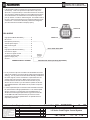
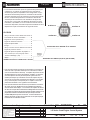
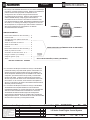
Additional features and bulkhead connector descriptions are
also included below.
System Features
• The Fuse/Relay center contains all required fuses and relays
for proper engine operation. Spare fuse and relay openings
are provided for possible future customer use.
• The Fuse/Relay center includes a malfunction indicator light
(MIL) which will illuminate in the event of an engine fault code.
See your GM Performance Parts dealer to have this code
retrieved at the diagnostic link connector in the fuse/relay
center (using a Tech2 with 2006 Cadillac CTS-V configuraSystem DOs and DON’Ts:
tion). Codes can also be retrieved using an aftermarket
Do:
diagnostic scan tool capable of reading this configuration.
• Ensure all intended engine/vehicle side connections are made
Note that the MIL will illuminate when the vehicle is keyed-up before connecting ignition or battery power to the system.
this is normal, and it will go out once the engine is started if
• Ensure the wiring harness is secured as required, and that the
there are no current fault codes. A redundant MIL wire is
routing avoids locations which can potentially damage the
included in the bulkhead connector (see below) to allow a light
wiring (e.g.: sharp edges, pinch points, rotating components,
to mounted inside the passenger compartment (this is recometc.). Make sure any unused connectors or wiring are propmended).
erly secured and protected (sealed or taped as required to
• A cooling fan can be controlled by the ECM. Control is set to
avoid short circuiting).
turn on a 12 V fan at 100 Deg C (212 Deg F) coolant tempera• Ensure all engine and wiring harness grounds are clean and
ture. The fan control wire is fused/relayed and can connect
secure. Minimum ¾ inch braided strap from the engine to the
directly to your Fan using 10 gauge wire (minimum size).
vehicle chasis is recommended.
• The fuel pump is controlled by the ECM. The control wire
• Ensure the MAF sensor is oriented correctly in the induction
supplies 12 V and is fused/relayed and should connect to the
(it will only read correctly in the proper direction). An arrow is
12 V side of the fuel pump using 10 gauge wire (minimum
located on the sensor indicating correct flow direction. Verify
size).
this before welding the mounting boss, as the sensor will
• Most GM late model LS series alternators are supported using
mount only one way in the boss.
the connection included in the harness. Refer to service
• Ensure the MAF Sensor is mounted in the middle of a miniinformation for details.
mum 6 inch length of 4 inch diameter tube, and is a minimum
of 10 inches from the throttle body.
• Ensure the fuel pressure is a constant 400 kPa (60 psi) with
the engine running. This is what the control system has been
developed to run.
• Ensure the fuel pump has the following flow capability: Minimum 40 gph @ 400 kPa for LS2/LS3/LS376’s and 50 gph @
400 kPa for LS7.
• Ensure battery voltage is connected using a minimum 8 gauge
wire to one of the studs on the fuse block.
• Ensure that the accelerator pedal clearances meet the guidelines above.
LS Series Crate Engine Control System
ALL INFORMATION WITHIN
ABOVE BORDER TO BE PRINTED
EXACTLY AS SHOWN ON 8.5 x 11
WHITE 16 POUND NON-BOND
RECYCLABLE PAPER.
PRINT ON BOTH SIDES, EXCLUDING TEMPLATES.
TO BE UNITIZED IN ACCORDANCE WITH GMSPO SPECIFICATIONS.
DATE
REVISION
REV 29SE08
AUTH
DR
TITLE
PART NO.
PART NO.
19171935
SHEET
3
OF
INSTALLATION INSTRUCTIONS
LS Series Crate Engine Control System
19171935
SHEET
3
OF
15
15