1
Table of contents
1
2
3
4
5
6
7
8
9
10
10.1
10.2
11
11.1
11.2
12
12.1
13
13.1
14
14.1
14.1.1
14.2
14.2.1
14.3
14.3.1
14.3.2
14.4
14.5
14.5.1
14.5.2
14.5.3
14.5.4
15
16
Safety instructions
Field of application
Functions of the data display
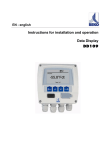
Data display with sensors
Technical data
Dimensions
Mounting
Plug reverse side
Connecting diagram reverse side
Connecting diagrams
Power supply
Alarm connection
Analogue current signal
Analogue current signal flow sensor
Analogue current signal DPsensor
Galvanic isolated pulse output
Connecting diagram pulse output flow sensor
Connection pulse: active high
Connection pulse: active low
Operation
Description of the display icons
Description of the status icons
Operation of the main keys
Concept for key operation
Typical menu display layout
Selection fields
Figure settings
Information after switching on the instrument
Main menu points
Logger operation
Alarm settings
Sensor settings
System status and settings
Scope of delivery
Conformity declaration
Data Display DD109
4
6
6
6
7
8
9
10
10
10
10
11
11
11
11
12
12
12
12
13
13
13
14
14
14
15
15
15
16
16
17
17
17
17
18
3