1
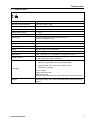
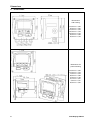
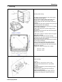
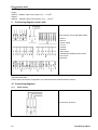
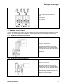
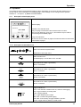
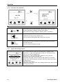
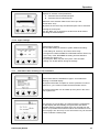
EN - english
Instructions for installation and operation
Data Display
DD109
Dear customer,
Thank you very much for deciding in favour of the data display DD109. Please read this installation and
operation manual carefully before mounting and initiating the device and follow our advice. A riskless
operation and a correct functioning of the data display are only guaranteed in case of careful observation of
the described instructions and notes.
Headquarter :
/ China
France
BEKO TECHNOLOGIES S.a.r.l.
Deutschland / Germany
BEKO TECHNOLOGIES (Shanghai) Co.
Ltd.
BEKO TECHNOLOGIES GMBH
Rm.606 Tomson Commercial Building
1 Rue des Frères Remy
Im Taubental 7
710 Dongfang Rd.
F- 57200 Sarreguemines
D-41468 Neuss
Pudong Shanghai China
Tel. +33 387 283 800
Tel.: +49 (0)2131 988 0
P.C. 200122
[email protected]
[email protected]
Tel. +86 21 508 158 85
Zone Industrielle
[email protected]
India
Italia / Italy
BEKO COMPRESSED AIR
TECHNOLOGIES Pvt. Ltd.
BEKO TECHNOLOGIES S.r.l
BEKO TECHNOLOGIES K.K
Via America 14
KEIHIN THINK 8 Floor
Plot No.43/1, CIEEP, Gandhi Nagar,
I - 10071 Borgaro Torinese (TO)
1-1 Minamiwatarida-machi
Balanagar, Hyderabad - 500 037, INDIA
Tel. +39 0114 500 576
Kawasaki-ku, Kawasaki-shi
Tel +91 40 23080275
[email protected]
JP-210-0855
[email protected]
/ Japan
Tel. +81 44 328 76 01
[email protected]
Benelux
Polska / Poland
Scandinavia
BEKO TECHNOLOGIES B.V.
BEKO TECHNOLOGIES Sp. z o.o.
BEKO TECHNOLOGIES AS
Vaartveld 25
ul. ChCapowskiego 47
P.O.Box 12 N-1393 Vollen
NL - 4704 SE Roosendaal
PL-02-787 Warszawa
Leangbukta 31
Tel. +31 165 320 300
Tel +48 (0)22 855 30 95
N-1392 VETTRE
[email protected]
[email protected]
Tel +47 31 29 10 50
[email protected]
España / Spain
South East Asia
/ Taiwan
BEKO Tecnológica España S.L.
BEKO TECHNOLOGIES S.E.Asia
(Thailand) Ltd.
BEKO TECHNOLOGIES Co.,Ltd
Polígono Industrial "Armenteres"
C./Primer de Maig, no.6
75/323 Romklao Road
Sintai 5th Rd., Sijhih City,
E-08980 Sant Feliu de Llobregat
Sansab, Minburi
Taipei County 221,
Tel. +34 93 632 76 68
Bangkok 10510
Taiwan (R.O.C.)
[email protected]
Thailand
Tel. +886 2 8698 3998
Tel. +66 (0) 2-918-2477
[email protected]
16F.-5, No.79, Sec. 1,
[email protected]
/eská Republica / Czech Republic
United Kingdom
USA
BEKO TECHNOLOGIES s.r.o.
BEKO TECHNOLOGIES LTD.
BEKO TECHNOLOGIES CORP.
Mlýnská 1392
2 West Court
900 Great SW Parkway
CZ - 562 01 Usti nad Orlici
Buntsford Park Road
US - Atlanta, GA 30336
Tel. +420 465 52 12 51
Bromsgrove
Tel. +1 (404) 924-6900
[email protected]
GB-Worcestershire B60 3DX
[email protected]
Tel. +44 1527 575 778
[email protected]
2
Data Display DD109
Table of contents
1
2
3
4
5
6
7
8
9
10
10.1
10.2
11
11.1
11.2
12
12.1
13
13.1
14
14.1
14.1.1
14.2
14.2.1
14.3
14.3.1
14.3.2
14.4
14.5
14.5.1
14.5.2
14.5.3
14.5.4
15
16
Safety instructions
Field of application
Functions of the data display
Data display with sensors
Technical data
Dimensions
Mounting
Plug reverse side
Connecting diagram reverse side
Connecting diagrams
Power supply
Alarm connection
Analogue current signal
Analogue current signal flow sensor
Analogue current signal DPsensor
Galvanic isolated pulse output
Connecting diagram pulse output flow sensor
Connection pulse: active high
Connection pulse: active low
Operation
Description of the display icons
Description of the status icons
Operation of the main keys
Concept for key operation
Typical menu display layout
Selection fields
Figure settings
Information after switching on the instrument
Main menu points
Logger operation
Alarm settings
Sensor settings
System status and settings
Scope of delivery
Conformity declaration
Data Display DD109
4
6
6
6
7
8
9
10
10
10
10
11
11
11
11
12
12
12
12
13
13
13
14
14
14
15
15
15
16
16
17
17
17
17
18
3
Safety instructions
1
Safety instructions
Please check whether this manual corresponds with the instruments type.
Please observe all notes indicated in this instruction manual. It contains essential information
which have to be observed during installation, operation and maintenance. Therefore this
instruction manual has to be read categorically by the technician as well as by the responsible
user / qualified personnel before installation, initiation and maintenance.
This instruction manual has to be available at the operation site of data display at any time.
Regional respectively national regulations have to be observed in addition to this instruction
manual, if necessary.
In case of any obscurities or questions with regard to this manual or to the instrument please
contact BEKO TECHNOLOGIES.
Warning!
Supply voltage!
Contact with supply voltage carrying non-insulated parts may cause an electric shock
with injury and death.
Measures :
•
Observe all applicable regulations for electrical installations (e. g. VDE 0100)!
•
Carry out maintenance work only in deenergized state!
•
All electric works are only allowed to be carried out by authorized qualified personnel.
Warning !
Inadmissible operating parameters !
Undercutting or exceeding of limit values may cause danger to persons and material
and may lead to functional and operational disturbances.
Measures :
•
Make sure that the data display is only operated within the admissible limit values indicated on the
type label.
•
Careful observation of the performance data of the data display in connection with the application.
•
Do not exceed the admissible storage and transportation temperature.
4
Data Display DD109
Safety instructions
Further safety instructions:
•
Also the applicable national regulations and safety instructions have to be observed during installation
and operation.
•
The data display is not allowed to be used in explosive areas.
Additional remarks:
•
Do not overheat the instrument!
Attention !
Malfunctions at the data display
Faulty installation and insufficient maintenance may lead to malfunctions of the data
display which may affect the measuring results and which may lead to
misinterpretations.
r
Data Display DD109
5
Field of application
2
Field of application
•
•
•
The data display is a stationary display instrument with data logger e. g. for corresponding consumption
and dew point sensors (please see "Technical data")
The data display is used e. g. in the following applications
Flow station
Dew point set
For functioning, the data display requires an operating voltage (see Technical data).
The data display is not suitable for an application in explosive areas
3
Functions of the data display
•
•
•
•
•
•
•
•
Graphics display for an easy user interface
Flexible voltage supply: 100… 240 VAC/ 50… 60Hz
2 inputs for BEKO consumption and dew point sensors
4… 20 mA – output for further processing
2 relay outputs for alarm
USB interface
Housing mountable at the wall or in the panel
Data logging function for 1,000,000 values
4
Data display with sensors
•
BEKO consumption sensor
BEKO dew point sensor
alarm output
4… 20 mA – output for further
processing
USB interface
6
Data Display DD109
Technical data
5
Technical data
Dimensions wall housing
Dimensions: 4.65“ x 4.53“ x 3.66“
Dimensions panel mounting
Dimensions: 3.62“ x 3.62“
Housing material
ABS synthetic material
Protection type housing
IP 65
Operating temperature
0… 122°F
Transportation temperature
-4… 158 °F
Sensor inputs
2 inputs for dew point and consumption sensors
(optional 2 analogue inputs)
Interface
USB
Keypad
4 keys
Power supply
100 .… 240 VAC / 50-60 Hz / 10 VA
Display
Graphics display, 160 x 100 pixels
Settings
The data display is supplied with standard settings
Alarm output
2 relays, 230 VAC, 3 A, potential-free, change-over contact
Analogue output
Connection of the 4… 20 mA signals of the dew point and consumption
sensors (maximum burden < 500 Ohm)
Data logger
up to 1,000,000 values
start time programmable and manually adjustable
logging interval, Min. 1 Sec., Max. 59 Min. 59 Sec.
average value storage
Factory settings:
Logging interval 10 Sek.
Wrap around mode
The data logging starts as soon as the instrument is put into operation
Software
Data Display DD109
The BEKO software SW 109 is available as an option. With this
software all settings can be done at DD109 and the logger data can be
read-out.
7
Dimensions
6
Dimensions
Dimensions
wall housing
118,0 mm = 4,65“
92,0 mm = 3,62“
115,0 mm = 4,53“
107,5 mm = 4,23“
133,0 mm = 5,24“
25,0 mm = 0,98“
20,0 mm = 0,79“
Dimensions for
panel mounting
118,0 mm = 4,65“
115,0 mm = 4,53“
13,5 mm = 0,53“
98,5 mm = 3,88“
70,0 mm = 2,76“
91,7 mm = 3,61“
8,0 mm = 0,31“
92,0 mm = 3,62“
8
Data Display DD109
Mounting
7
Mounting
Mounting wall housing:
The cables for sensors and for the power supply
are already wired at DD10:
• Do not connect mains cable to the power line
• Release the 4 screws at the front housing
• Remove plug from the reverse side of the front
housing
• Drill holes into the wall according to the given grid
dimension (please see drawing)
• Mount wall housing (anchor and screws included
in the scope of delivery)
• Attach again plug for the power supply and for
the sensors
• Insert the front housing into the wall housing and
tighten the 4 screws
At DD109 the cables for sensors and for the power
supply are not wired:
• Release the 4 screws at the front housing
• Drill holes into the wall according to the given grid
dimension (please see drawing)
• Mount wall housing (anchor and screws included
in the scope of delivery)
• Carry out wiring of the power supply and the
sensor(s) according to the below instructions
• Insert the front housing into the wall housing and
tighten the 4 screws
• Tighten the clamp screwings of the cables
98,8 mm = 3,89”
84,0 mm = 3,31”
Panel mounting
• Cut-out
3,62” (+0,03” -0,0”) x 3,62” (+0,03” -0,0”)
Maximum sheet thickness 0,31” (see above
drawing)
• Insert front housing for panel mounting into the
prepared cut-out
• Insert the fixing clips and fix the housing by
twisting the thread rods
• Carry out wiring of the power supply and the
sensor(s) according to the below instructions
Data Display DD109
9
Plug reverse side
8
Plug reverse side
Supply:
2
AWG12 – AWG24, cable cross-sections: 0.2 ... 2.5 mm
Signals:
2
AWG16 ... AWG28, cable cross-sections: 0.14 ... 1.5 mm
9
Connecting diagram reverse side
Wiring scheme reverse side data display:
A: Alarm 1
B: Alarm 2
C: Power supply
D: no use
E: optional
F: optional
G: Flow sensor
H: Galvanically separated pulse output
flow sensor
I: DPsensor
Important information:
Please make sure that the configuration you ordered has been matched with the sensors.
10 Connecting diagrams
10.1
Power supply
100-240 VAC, 50-60 Hz
10
Data Display DD109
Analogue current signal
10.2
Alarm connection
NC and COM are closed in case of:
- alarm
- power failure
- sensor break
11 Analogue current signal
The flow sensor and the DP sensor offer the possibility to provide the measured values as analogue current
signal 4…20 mA for further process treatment . The connection schemes have already been set for this.
11.1
Analogue current signal flow sensor
Terminal G "Flow sensor“
The flow sensor is connected to the clamps
at terminal G according to the scheme
indicated at the left. The analogue signal
(4...20mA) is at clamp 1 and 3 and can be
tapped if required (maximum burden
< 500 Ohm)
11.2
Analogue current signal DPsensor
Terminal I „DP sensor“
The DP sensor is connected to the clamps
at terminal I according to the scheme
indicated at the left. The analogue signal
(4...20mA) is at clamp 1 and 2 and can be
tapped if required (maximum burden
< 500 Ohm). If the analogue signal is not
used a wire jumper has to be inserted here
obligatorily (factory-provided)
Data Display DD109
11
Galvanic isolated pulse output
12 Galvanic isolated pulse output
A galvanic isolated pulse output is available for the flow sensor. It deals with a semi-conductor relay which is
galvanic isolated from the supply voltage by means of optoelectronic couplers.
Maximum switching capacity : Umax: 32V, Imax: 20 mA
12.1
Connecting diagram pulse output flow sensor
Pulse counter flow sensor to terminal H
clamps 1 and 2
13 Connection pulse: active high
active high
13.1
Connection pulse: active low
active low
12
Data Display DD109
Operation
14 Operation
The measured values will be indicated page by page. Depending on the sensor and the settings one or
several values can be indicated on one display page. These settings can be changed via the optional
software or - on request - by BEKO TECHNOLOGIES.
14.1
Description of the display icons
Status display
Indication of measured value:
Only one page of measured values will be shown at a time.
The use can utilize the „arrow up“ or „arrow down“ keys in order to
scroll through all available pages.
Page view indication:
Shows the current number of pages of measured values as well as the
total number of pages.
14.1.1 Description of the status icons
These icons show the system status.
Explanation of the single icons:
USB connection icon:
The data display is connected to a PC via USB
Alarm status icon: Alarm 1 (pre-alarm)
Alarm 1 is exceeded
ALM1
Alarm status icon: Alarm 1 (pre-alarm)
Alarm 1 is undercut
Alarm status icon: Alarm 2 (main alarm)
Alarm 2 is exceeded
Alarm status icon: Alarm 2 (main alarm)
Alarm 2 is undercut
Logger module icon:
WAIT: Time and start conditions are set, waits for start logging
LOG: Logger module is recording data
STOP: Logging stopped
DEL: Logger deletes protocol data
ERR: Error occured during data logging
LOG 100%: Free memory of logger module in percent
CYCLE: Logger memory works in circular mode
Data Display DD109
13
Operation
14.2
Operation of the main keys
14.2.1 Concept for key operation
- 4.0 °Ftd
• use these keys to browse and select different items in the menu and
scroll through different pages of measurement values
• use these keys to alter or adjust the setting option or numbering
Back
Enter
14.3
• use this key to exit the current menu level
• use it to leave all setting state without saving the changes
• use this key to enter the submenu or next menu level of the currently
selected menu item
• use it to confirm the setting changes
Typical menu display layout
• The currently selected menu item will be shown in negative colour
• If there is a ">“ sign at the right edge it means we can exit the current
menu or go to the next higher level
• It there is a "<“ sign at the left edge it means we can go into the
submenu of the currently selected menu
• Selectable menu item. It shows 4 items at the same time. If the total
items in the current menu are more than 4 items the menu items can be
scrolled through
• Indication at the bottom:
Shows how many items exist in the currently selected menu and it shows
the current menu item
14
Data Display DD109
Operation
14.3.1 Selection fields
• Options for selection of the parameters
- Selection field for deselected point
- Selection field for selected point
• Selection of the selection field via the "arrow up“ and
"arrow down“ keys
• By means of the "Enter“key the selected option can be activated
• Leaving the menu point:
Use the "Back“ key to get back to the last menu level without
activating the selected option
14.3.2 Figure settings
Example figure settings:
Time and date setting in submenu "system status and setting"
1. Time setting via "arrow up" and "arrow down" keys
2. Change from HOUR to MINUTE to SECOND with the "Enter“ key
3. Upon entry of the SECONDS the setting is terminated and
stored by the "Enter“ key.
By using the "Back" key the menu point "Time and date
setting" can be left without storing the settings.
14.4
Information after switching on the instrument
System information are indicated for approx. 5 seconds after
switching on the data display:
The system information is helpful for service questions in order to
determine e. g. the version number and the firmware version.
The system information can be called up at any time in the menu
point "system info".
If the sensors are connected in accordance with the configuration
the data display will automatically recognize them and start to
indicated real time measured values which are received from the
sensors. It is possible that measured values are indicated on more
than one page. The "arrow up" or the "arrow down" key can be used
in order to indicate a further page.
Data Display DD109
15
Operation
14.5
Main menu points
The data display is supplied with standard settings.
Main menu points in the data display:
• Logger operation
• Set Alarm 1
• Set Alarm 2
• Sensor setting
• Communication settings (Option BUS systems)
• System status and setting
14.5.1 Logger operation
Set logging rate
Set storage interval and average value determination
The storage interval defines the time interval in which the data should be
recorded. One value is recorded of each activated channel. The option average
value determination can be used in order to determine the average value, i. e.
the data display measures every second and if the storage interval is 10
seconds the average from the last 10 values will be made up and stored as
measured value.
Key start logging
Start/stop, recording
Starts or stops the data recording. A new file is created in the memory as soon
as a new recording is started.
Set time start condition
Set time, start conditions
The data display can be programmed so that it starts measurement at a certain
point of time.
Memory status
Show logger memory status
Shows the status and the size of the available memory
View protocol
Single protocols (files) or the whole memory can be indicated and if necessary
deleted. The data display shows the available protocols with date, the number of
channels, the number of recorded data per channel and the min/max/average
value.
Delete protocol
Deletes the selected protocol.
Format logger
Deletes the internal memory.
16
Data Display DD109
Scope of delivery
14.5.2 Alarm settings
It is possible to set 2 individual alarm thresholds:
1. “Set Alarm 1 threshold”
2. ”Set Alarm 2 threshold”
In this example the sensor is connected to terminal I.
„Type: High" means:
The alarm is triggered if the value is higher than the threshold.
If the alarm is exceeded or dropped below the background
becomes red resp. starts blinking.
The factory setting of the hysteresis is 35°F td.
Please observe that these adjustments cannot be changed directly
in the Data Display.
Please turn to BEKO TECHNOLOGIES GMBH
14.5.3 Sensor settings
Sensor settings for our consumption or dew point sensors are stored within the sensor itself. The Data
Display can be used in order to change those settings. For this purpose, select in the menu the function
“Sensor settings”. On the next screen the available inputs are shown: e. g.
Terminal I: Dew point
Terminal G: Consumption
Select the desired entry mask in order to carry out the sensor settings.
If a sensor is connected to a switched on Data Display, the configuration of the Data Display will be
transferred to the sensor without any prior query. (e.g. analogue output, diameter for consumption probes …)
On delivery of a unit Data Display/sensor the adjustments are matched. Please check the coordination if you
connect sensors with deviant adjustments to the Data Display.
14.5.4 System status and settings
Setup time/date
Set the integrated clock.
Show system status
This screen contains important information for service enquiries.
Change LCD contrast
Contrast of the display can be changed.
System reset
In case other sensors are connected it is recommended to use this
function in order to update the system settings.
15 Scope of delivery
•
•
•
Data Display in wall housing according to your order
Fastening clips for panel mounting
Instruction manual
Data Display DD109
17
Conformity declaration
16 Conformity declaration
18
Data Display DD109
Conformity declaration
BEKO TECHNOLOGIES GMBH
41468 Neuss, GERMANY
Phone: +49 2131 988-0
www.beko.de
EC Declaration of Conformity
We herewith declare that the product indicated in the following in the version supplied by us corresponds
with the requirements of the relevant standards:
Product designation:
Voltage supply:
Product description and function:
Low voltage directive 2006/95/EG
Applied harmonized standards:
Year of fitting with CE mark:
EMV directive 2004/108/EG
Applied standards:
DD109
100 – 240 VAC / 50-60 Hz / 10 VA
Data display for recording and indication of measured
data
EN 61010-1:2001
EN 61010-31:2002 + A1:2008
09
Emitted interference:
EN 61326:1997 + A1:1998 + A2:2001 + A3:2003
Interference resistance:
EN 61326:1997 + A1:1998 + A2:2001 + A3:2003
The products are labeled with the indicated mark:
This declaration only refers to the products in the state in which they are put into circulation, parts which are
not attached by the manufacturer and/or subsequently taken interventions stay unconsidered.
Neuss, 30.03.2009
BEKO TECHNOLOGIES GMBH
i.V. Christian Riedel
Head of Quality Management
Data Display DD109
19
A
L
Active high ..........................................................12
Active low............................................................12
Alarm 1 (pre-alarm) ............................................13
Alarm 1 exceeded...............................................13
Alarm 1 undercut ................................................13
Alarm 2 (main alarm) ..........................................13
Alarm connection................................................11
Alarm exceeded or dropped below.....................17
Alarm settings .....................................................17
Analogue current signal 4...20 mA .....................11
Applications ..........................................................6
Logger module icon ............................................13
Logger operation.................................................16
B
Back key .............................................................14
C
Concept for key operation ..................................14
Conformity declaration........................................18
Connecting diagram reverse side.......................10
Connection pulse: active high ............................12
Connection pulse: active low ..............................12
Contrast of the display........................................17
M
Main functions of the data display ........................6
Main menu points ...............................................16
Maximum switching capacity ..............................12
Mounting ...............................................................9
Mounting wall housing ..........................................9
O
Operating voltage .................................................6
Operation of the main keys.................................14
P
Panel mounting .....................................................9
Power supply ......................................................10
Process treatment...............................................11
Pulse counter ......................................................12
Pulse output flow sensor.....................................12
Q
Qualified personnel...............................................4
D
R
Data display with sensors.....................................6
Dimensions ...........................................................8
Dimensions for panel mounting ............................8
Dimensions wall housing ......................................8
Display icons ......................................................13
Red background .................................................17
E
Enter key.............................................................14
Explosive area ......................................................6
F
Faulty installation..................................................5
Field of application................................................6
Figure settings ....................................................15
S
Safety instructions ................................................5
Safety instructions ................................................4
Scope of delivery ................................................17
Selection field parameters ..................................15
Sensor settings ...................................................17
Status icons ........................................................13
System status and settings.................................17
T
Technical data ......................................................7
Typical menu display layout................................14
G
U
Galvanically separeted pulse output ..................12
USB interface........................................................6
H
W
Hysteresis ...........................................................17
Warning inadmissible operating parameters ........4
Warning supply voltage ........................................4
I
Information after switching on the instrument.....15
20
Data Display DD109
Conformity declaration
Data Display DD109
21
22
Data Display DD109
Conformity declaration
Data Display DD109
23
Technical changes and errors excepted.
DD109_manual_en_2009-03