1
FRANÇAIS
E S PA Ñ O L
iWISE™ DT PET
iWISE™ DT PET
• Full pet immunity up to 45 kg (100 lb) dog, 6 cats.
• Superior catch performance.
• 2 lenses supplied for different installation heights:
– Installation height 2.4m (7’11”)– detection area:
8m x 8m (27ft x 27ft) - factory installed.
– Installation height 2.1m (6’11”)– detection area:
11m x 11m (35ft x 35ft) - supplied.
• Active creep zone to ensure pet immunity without loss of
intruder detection.
• Unique VPT algorithm (Patent Pending).
• Patented true temperature compensation.
• Dual PIR and microwave technologies.
CARATÉRISTIQUES DE l'i WISE DT PET
• Immunité totale aux animaux domestiques jusqu'à
45 kg
(100 lb.) pour un chien, soit 6 chats,
Supériorité des performances de capture,
• 2 lentilles fournies pour différentes hauteurs de montage :
• Hauteur de montage 2,4 m (7'11") – zone de détection :
8 m x 8 m (27' x 27') – lentille montée en usine,
• Hauteur de montage 2,1 m (6'11") – zone de détection :
11 m x 11 m (35' x 35') – lentille fournie.
• Zone d'intrusion active pour assurer l'immunité aux animaux
domestiques sans perte de la capacité de détection d'intrus,
• Algorithme VPT unique (brevet en instance),
• Réelle compensation de la température, brevetée.
• Double technologie MW et PIR,
CARACTERISTICAS DEL iWISE DT PET
• Inmunidad completa a un perro de hasta 45 kg (100 lb), 6 gatos.
• Desempeño de captura superior.
• 2 lentes proveídas para distintas alturas de instalación:
– Altura de instalación de 2.4 m (7’11”) – área de detección:
8m x 8m (27ft x 27ft) – instalación de fábrica.
– Altura de instalación de 2.1m (6’11”) – área de detección:
11m x 11m (35ft x 35ft) - proveída.
• Zona activa de arrastramiento para asegurar inmunidad al animal
doméstico sin pérdida de detección del intruso.
• Algoritmo único de VPT (Patente Pendiente)
• Compensación de Temperatura Verdadera (Patentada)
• Tecnología Dual PIR y microondas.
DETECTION IS BASED ON:
PIR (passive infra-red) which responds to changes in the ambient
thermal radiation caused when an intruder crosses the protected
area.
MW (microwave), which transmits signals and analyzes the frequency
changes of the reflected signal from an intruder using the Doppler
effect.
An ALARM is initiated only when both technologies trigger
simultaneously.
Detection occurs only in areas where IR and MW patterns overlap
thus greatly reducing the possibility of false alarms.
PRINCIPE DE BASE DE LA DÉTECTION :
PIR (Infrarouge passif) qui réagit aux changements de radiations
thermiques ambiantes se produisant lorsqu'un intrus pénètre la
zone protégée.
MW (micro-onde) qui transmet, signale et analyse les modifications
de fréquence du signal reflété par un intrus, grâce à l'effet Doppler.
L'Alarme ne retentit que lorsque les deux technologies se
déclenchent en même temps.
La détection ne se produit que dans les zones où les schémas
IR et MW se superposent, réduisant ainsi considérablement les
risques de fausses alertes.
iWISE™ DT PET
The iWISE™ DT PET provides full pet immunity with no loss of
catch performance. The iWISE DT PET model easily distinguishes
between intruders and pets, allowing complete pet freedom of
movement without false alarms.
iWISE DT PET FEATURES
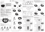
LED DISPLAY (See Fig. 1.)
When LED Jumper is ON:
• YELLOW LED indicates PIR detection
• GREEN LED indicates MW detection
• RED LED indicates alarm (simultaneous PIR and MW
detection).
• At Power-up, the LEDs will blink continuously, one after the
other, until the end of the warm-up period (2-3 minutes).
INSTALLATION
PRELIMINARY CONSIDERATIONS
Before installation, study the space to be protected carefully in
order to choose the exact placement of the unit and lens for the
best possible coverage.
Corner installations are recommended. The Detector should be
installed so that the beam patterns are at 45º (optimal) to the
intruder's expected path.
WARNING: THE UNIT SHOULD NOT BE MOUNTED IN
DIRECT SUNLIGHT OR NEAR ANY HEAT SOURCES. THE
DETECTION SECTORS SHOULD BE POINTED EITHER
TOWARDS A WALL OR TOWARDS THE FLOOR (NOT
TOWARDS WINDOWS NOR CURTAINS). INSTALL ON
SMOOTH SURFACES ONLY.
OPENING THE FRONT COVER
To open the front cover, turn the screw 3 full turns counterclockwise.
With the screw loosened, press it 'in' to release the front cover.
If a fixing screw is not used, press the tab, which is located behind
the screw hole. The front cover can now be removed.
REMOVING THE PC BOARD
Loosen the holding screw, which is located on the right hand side
of the PCB and slide the PCB up until the screw enters the widened
opening. The PCB can now be lifted off.
MOUNTING
PET IMMUNTY
In order to optimize pet immunity the following guidlines are
recommended:
a. Mount the sensor vertically at right angles to the floor. b.
Mount the sensor at a height of 2.1m (6'11") with the RL-111
lens and 2.4m (7‘11“) with the RL-108 lens.
c. Make sure an animal cannot get above the height of 1.5m (5”)
by jumping on furniture or shelving.
d. Do not mount opposite stairways where animals have access.
The iWISE DT PET can either be mounted on a flat surface or in
a corner.
a. Open the knockout holes on the rear cover.
b. Insert the cable through the cable opening.
c. Mount the rear cover in its final location.
d. Seal the remaining holes with sealant.
e. After mounting the rear cover, return the PCB into its desired
position.
PC BOARD ADJUSTMENT
After the Detector base has been mounted, reinstall the PCB. In
order to optimize the PET Immunity, slide the PCB down until the
screw has stopped at the end of the keyhole.
TERMINAL WIRING
Connect the cable to the terminal block at the top of the PCB as
follows:
12 VDC: Power supply input.
ALARM: Normally closed output.
TAMPER: Normally closed dry output.
JUMPER SETTING (See Fig. 2.)
The iWISE DT PET has two jumpers that can either be in (used)
or out (unused).
Unused jumpers should be placed on one pin only to prevent
their loss.
WALK TEST
Two minutes after applying power (warm-up period), walk test the
Detector over the entire protected area to verify proper operation
of the unit.
NOTE:
• Ensure you replace the front cover before carrying
out a Walk Test.
• The MW range can be adjusted by using the
potentiometer, which is located at the bottom of the
PCB. It is important to set the potentiometer to the
lowest possible setting that will still provide enough
coverage for the entire protected area.
FINAL SETUP
After completing the installation and the testing stages, ensure all
jumpers are in their desired positions. The unit is now ready for
use.
Le détecteur iWISE™ DT PET procure une immunité totale aux
animaux domestiques sans rien perdre des performances de
capture. Le modèle iWISE™ DT PET fait très nettement la distinction
entre les intrus et les animaux domestiques, permettant ainsi à
ces derniers une absolue liberté de mouvements sans provoquer
de fausses alertes.
LA DETECCIÓN ESTÁ BASADA EN:
PIR (infrarrojo pasivo) que responde a los cambios en la radiación
termal del ambiente causados cuando un intruso cruza el área
protegida.
MW (microondas), que transmite señales y analiza la frecuencia
de la señal reflejada de un intruso usando el efecto de Doppler.
Una ALARMA es iniciada solamente cuando ambas tecnologías
disparan simultáneamente.
La detección ocurre solamente en áreas donde los modelos de
IR y MW se superponen y de esta manera reduciendo enormemente
la posibilidad de falsas alarmas.
AFFICHAGE À DIODES LED (Cf. Fig. 1)
Lorsque le cavalier LED est allumé (ON) :
• La diode LED JAU N E indique une détection PI R,
• La diode LE D VE RTE indique une détection MW,
• La diode LED ROUGE indique une alarme (détection simultanée
PIR et MW).
• Lors de la mise sous tension, les diodes LED clignotent sans
cesse l'une après l'autre jusqu'à la fin de la séquence
d'échauffement (2 à 3 minutes).
INDICADORE DEL LED (Ver Fig. 1.)
Cuando el cable de conexión del LED está en la posición ON:
• LED AMARILLO indica detección PIR
• LED VERDE indica detección MW
• LED ROJO indica alarma (detección simultánea PIR y MW).
• Al conectarse, los LEDs van a centellear continuamente hasta
el final del periodo de calentamiento (2-3 minutos).
INSTALLATION
PASO 1
ETAPE 1 CONSIDÉRATIONS PRÉLIMINAIRES
Avant l'installation, étudiez avec soin l'espace à protéger afin de
choisir l'emplacement exact de l'appareil et de la lentille pour
obtenir la meilleure couverture possible du point de vue des
dimensions.
Il est recommandé de procéder à des installations en coin. Le
détecteur doit être installé de sorte que les divers faisceaux se
situent à 45° (optimal) du passage supposé de l'intrus.
ATTENTION: L'APPAREIL NE DOIT PAS ÊTRE MONTÉ EN
EXPOSITION DIRECTE À LA LUMIÈRE DU SOLEIL NI À
PROXIMITÉ DE SOURCES DE CHALEUR. LES ZONES DE
DÉTECTION DOIVENT ÊTRE DIRIGÉES SOIT VERS UN
MUR SOIT VERS LE SOL (ET NON VERS UNE FENÊTRE
NI VERS DES RIDEAUX). À INSTALLER SUR SURFACES
LISSES SEULEMENT.
ETAPE 2
OUVERTURE DU COUVERCLE FRONTAL
Pour ouvrir le couvercle frontal, effectuez 3 tours complets de vis
dans le sens inverse des aiguilles d'une montre. Une fois la vis
relâchée, appuyez-la pour dégager le couvercle frontal. Si vous
n'utilisez pas de vis de maintien, appuyez sur la languette située
derrière le trou de la vis. Vous pouvez à présent retirer le couvercle
frontal.
ETAPE 3
RETRAIT DU TABLEAU PC
Dévissez la vis de maintien qui est située sur le côté droit du PCB
(PC Board) et faites glisser le PCB jusqu'à ce que la vis entre dans
l'ouverture élargie. Le PCB peut être maintenant soulevé et retiré.
ETAPE 4
MONTAGE
IMMUNITÉ AUX ANIMAUX DOMESTIQUES
Pour optimaliser l'immunité aux animaux domestiques, il est
recommandé d'appliquer les directives suivantes:
a. Installez le détecteur verticalement, perpendiculairement au
sol.
b. Installez le détecteur à hauteur de 2,1m (6'11") avec la lentille
RL-111 et 2,4m (7'11") avec la lentille RL-108.
c. Assurez-vous qu’un animal ne puisse pas passer au-dessus
du seuil de 1.5m (5") de hauteur, en sautant sur un meuble
ou un système d’étagères.
d. N’installez pas l’appareil face à des escaliers auxquels les
animaux auraient accès.
L'iWISE DT PET peut être monté soit sur une surface plane soit
en angle.
a. Ouvrez les trous situés sur le couvercle arrière.
b. Introduisez le câble dans l'ouverture qui lui est destinée.
c. Installez le couvercle arrière à sa place définitive.
d. Bouchez les trous restants avec du mastic.
e. Après avoir monté le couvercle arrière, remettez le PCB dans
la position souhaitée.
ETAPE 5
RÉGLAGE DU TABLEAU PC
Après avoir monté la base du détecteur, réinstallez le PCB. Pour
optimaliser l'immunité aux animaux domestiques, faites glisser le
PCB vers le bas jusqu'à l'arrêt de la vis au bout de l'orifice.
ETAPE 6
CÂBLAGE DES TERMINEAUX
Connectez le câble au bloc du terminal en haut du PCB comme
suit :
12 VDC: entrée de l'alimentation électrique,
ALARME: sortie normalement fermée,
AUTOPROTECTION: sortie sèche normalement fermée.
ETAPE 7
INSTALLATION DES CAVALIERS (CF. FIG. 2)
INSTALACIÓN
CONSIDERACIONES PRELIMINARES
Antes de la instalación, estudie cuidadosamente el espacio a ser
protegido por el detector, con la finalidad de seleccionar la ubicación
exacta de la unidad y la lente apropiada para conseguir la mejor
cobertura posible.
Son recomendadas instalaciones en los rincones. El detector debe
ser instalado de tal manera que la dispersión del rayo esté a 45º
(óptimo) del camino previsto del intruso.
ADVERTENCIA: LA UNIDAD NO DEBE SER MONTADA
FRENTE A LUZ SOLAR DIRECTA O CERCA DE FUENTES
DE CALOR. LOS SECTORES DEBEN APUNTAR HACIA UNA
PARED O AL PISO (NO HACIA VENTANAS NI CORTINAS).
INSTALE SOLAMENTE SOBRE SUPERFICIES LISAS.
PASO 2
ABRIENDO LA TAPA DELANTERA
Para abrir la tapa delantera, gire el tornillo 3 vueltas completas en
sentido opuesto a las agujas del reloj. Con el tornillo aflojado
apriételo para a dentro para liberar la tapa delantera. Si un tornillo
de fijación no es usado, apriete la aleta, que está ubicada detrás
del agujero del tornillo. La tapa delantera puede ahora ser removida.
PASO 3
REMOVIENDO LA PLACA DEL PC
Afloje el tornillo de mantenimiento, que está ubicado en el lado
derecho del PCB y deslice el PCB hacia arriba hasta que el tornillo
entre en la apertura ensanchada. El PCB pueda ahora ser
desplegado.
PASO 4
MONTAJE
INMUNIDAD A ANIMALES DOMÉSTICOS
Para optimizar la inmunidad al animal doméstico las siguientes
directrices son recomendadas:
a. Montar el sensor verticalmente a un ángulo recto con respecto
al piso.
b. Montar el sensor a una altura de 2.1m (6'11") con la lente RL111 y a 2.4m (7‘11“) con la lente RL-108.
c. Asegurar que un animal no pueda llegar a una altura de más
de 1.5m (5’) saltando muebles o estanterías.
d. No montar la unidad frente a una escalera accesible a los
animales.
El iWISE DT PET puede ser montado en una superficie plana o en
un rincón.
a. Abrir los agujeros pre-marcados en la tapa posterior.
b. Insertar los cable a través de la apertura para cables.
c. Montar la tapa posterior en su ubicación final.
d. Cerrar los agujeros que quedan con sellante.
e. Después de montar la tapa posterior, retornar el PCB a su
posición deseada.
PASO 5
AJUSTES DE LA PLACA DEL PC
Después que la base del Detector haya sido montada, reinstale
el PCB. Para optimizar la inmunidad del PET, deslice el PCB hacia
abajo hasta que el tornillo pare al final del ojo de la cerradura.
PASO 6 CONEXIÓN CABLEADO DE LOS TERMINALES
Conecte el cable al bloque de la terminal en la parte superior del
PCB como sigue:
12 VDC: Entrada de la fuente de alimentación.
ALARMA: Salida normalmente cerrada.
TAMPER: Salida seca normalmente cerrada.
PASO 7
JUMPER POSICIONES
(Ver Fig. 2.)
El iWISE PET tiene dos cables de conexión que pueden estar in
(en uso) o out (sin uso).
Los cables de conexión sin uso deben ser colocados en una única
clavilla para evitar su pérdida.
L' iWISE DT PET dispose de deux cavaliers qui peuvent être utilisés
(IN) ou inutilisés (OUT).
Les cavaliers inutilisés doivent être placés sur une broche afin
d'éviter de les perdre.
ETAPE 8
TEST DE PASSAGE À PIED
Deux minutes après avoir réalisé la mise sous tension (séquence
d'échauffement), faites un test de passage à pied pour vérifier
l'efficacité du détecteur sur la totalité de la zone protégée.
REMARQUES:
• Assurez-vous de bien replacer le couvercle frontal
avant d'effectuer le test de passage à pied.
• La portée MW doit être réglée à l'aide du
potentiomètre situé au bas du PCB. Il est important
de régler le potentiomètre sur le niveau le plus bas
possible permettant de couvrir la totalité de la surface
de la zone à protéger.
ETAPE 9
RÉGLAGE FINAL
Après avoir terminé l'installation et les tests, assurez-vous que
tous les cavaliers sont bien dans la position voulue. L'appareil est
maintenant prêt à fonctionner.
The MW range must be adjusted to the minimum needed,
using the potentiometer located at the bottom of the PCB. It
is important that the potentiometer is set to its lowest possible
setting, which will provide full coverage for the entire protected
area. It is recommended that the Detector is installed only in
square rooms.
La portée MW doit être réglée au minimum requis à l'aide du
potentiomètre situé au bas du PCB. Il est important de régler
le potentiomètre sur le niveau le plus bas possible permettant
de couvrir la totalité de la surface de la zone à protéger. Il est
recommandé de n'installer le détecteur que dans des pièces
carrées.
Refer to Fig. 5
Cf. Fig. 5.
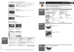
PROCEDURE FOR CHANGING LENSES (See Fig. 4.)
A pigmented lens is attached to the inside of the front plastic
cover using a sensor protective sleeve.
1. Remove the sensor protecting sleeve by pushing up the clip
that holds the top part of the sleeve to the front cover.
2. Disconnect the lens from the sleeve by gently lifting it
from the holding pins that secure it to the sides of the sleeve.
3. Select the desired lens and make sure that the cut corners are
pointed upwards.
4. Place the two pins, which are located on the top and bottom
of the lens, into the matching holes on the sleeve.
5. Place the holes on either side of the lens into their matching
holding pins located on the sides of the sleeve.
6. Insert the protective sleeve back into place on the front
cover.
El iWISE™ DT PET proporciona inmunidad completa al animal
doméstico sin pérdida de desempeño de captura. El modelo iWISE
PET distingue fácilmente entre intrusos y animales domésticos,
permitiendo al animal completa libertad de movimiento, sin falsas
alarmas.
PROCÉDURE DE CHANGEMENT DES LENTILLES
(Cf. Fig. 4)
Une lentille teintée est fixée à l'intérieur du couvercle frontal en
plastique à l'aide d'une douille protégeant le détecteur.
1. Retirez la douille qui protège le détecteur en poussant vers
le haut l'agrafe qui retient le haut de la douille au couvercle
frontal.
2. Séparez la lentille de la douille en la relevant doucement des
broches de maintien qui la fixent aux côtés de la douille.
3. Sélectionnez la lentille souhaitée et assurez-vous que les
angles aigus sont bien orientés vers le haut.
4. Placez les deux broches qui se trouvent en haut et en bas de
la lentille dans les trous correspondants de la douille.
5. Faites correspondre les trous latéraux de la lentille aux broches
de maintien qui leur font face sur les côtés de la douille.
6. Réinsérez la douille de protection à sa place sur le couvercle
frontal.
I TA L I A N O
iWISE™ DT PET
iWISE™ DT PET è un rivelatore che discrimina gli animali
domestici garantendo una ottima rilevazione degli intrusi.
Tramite algoritmi proprietari e lenti appositamente progettate
iWISE™ DT PET discrimina gli impulsi infrarossi generati
dagli animali domestici ignorando questi segnali e generando
l'allarme solo in caso in cui l'area protetta sia stata violata
da un intruso. Questo rivelatore permette di inserire l'impianto
d'allarme pur avendo un animale domestico in casa evitando
di generare allarmi impropri.
CARATTERISTICHE iWISE DT PET
• Discriminazione degli animali fino a un massimo di 45kg
per un cane, 6 gatti.
• Eccezionale capacità di rivelazione.
• 2 lenti fornite per due diverse altezze
d’installazione:
- Altezza: 2.4m - area di rivelazione 8 x 8 metri
(configurazione di fabbrica).
- Altezza 2.1m – area di rivelazione: 11 x 11 metri
(lente fornita).
• Zona antistrisciamento attiva per garantire
l’immunità agli animali senza compromettere
la rivelazione di intrusi.
• Esclusivi algoritmi VTP a soglie di immunità variabili
per la corretta discriminazione degli animali dagli
intrusi (brevetto in corso).
• Compensazione reale della temperatura brevettata.
• Doppia tecnologia PIR e Microonde
LA RIVELAZIONE SI BASA SU:
PIR: (infrarosso passivo) rileva la variazione di calore generata
da un intruso che attraversa l'area protetta dal rivelatore.
MW: (Microonde) trasmette segnali ed analizza la frequenza dei
segnali riflessi da un intruso mediante l’effetto Doppler.
L’allarme scatta solo quando entrambe le tecnologie sono
interessate simultaneamente.
La rivelazione avviene esclusivamente nelle aree coperte dalla
portata dell'infrarosso e della microonda garantendo così una
drastica riduzione dei falsi allarmi.
INDICATORI LED (Fig. 1)
Quando il ponticello di abilitazione LED è sul ON (inserito):
• LE D G IALLO indica rivelazione canale infrarosso
• LE D VE R DE indica rivelazione canale microonda
• LED ROSSO indica l’allarme (rivelazione simultanea del canale
infrarosso e di quello microonda)
• Alimentando l'unità, gli indicatori LED lampeggeranno in
sequenza fino alla fine del periodo di riscaldamento (2 – 3
minuti)
INSTALLAZIONE
FASE 1 CONSIDERAZIONI PRELIMINARI
Prima dell’installazione, studiare con attenzione l'area da
proteggere per poter scegliere l’ubicazione esatta dell’unità
per la miglior copertura possibile.
Sono raccomandate le installazioni angolari. Il rivelatore
deve essere installato in modo che un possibile intruso
attraversi l'area protetta perpendicolarmente rispetto alla
posizione del rivelatore.
ATTENZIONE: L’UNITA’ NON DEVE ESSERE MONTATA DI
FRONTE ALLA LUCE DIRETTA DEL SOLE O VICINO A
SORGENTI DI CALORE. I SETTORI DI RIVELAZIONE
DOVREBBERO ESSERE PUNTATI VERSO IL MURO O IL
PAVIMENTO (NON VERSO FINESTRE O TENDE).
I N S TA L L A R E S O LO S U S U P E R F I C I P I A N E .
FASE 2 APERTURA DEL COPERCHIO ANTERIORE
Per aprire il coperchio, girare la vite in senso antiorario per
3 giri completi. Premere leggermente la vite allentata verso
l’interno e rimuovere il coperchio. Se non è stata utilizzata
la vite, premere leggermente verso l’interno la linguetta
plastica posizionata dietro il foro della vite e rimuovere il
coperchio
FASE 3 RIMOZIONE DELLA SCHEDA ELETTRONICA
Allentare la vite di fissaggio, situata nella parte destra della
scheda e far scorrere verso l'alto la scheda finché la vite
non raggiunge il foro di uscita circolare. La scheda può ora
essere rimossa.
FASE 4
POSIZIONAMENTO
PER LA DISCRIMINAZIONE ANIMALI
Per ottimizzare l’immunità degli animali, seguire le istruzioni
di seguito elencate:
a. Montare il dispositivo perpendicolarmente
al pavimento.
b. Montare il dispositivo all’altezza di 2.1m con la lente RL111 e 2.4m con la lente RL-108.
c. Verificare che nessun animale possa raggiungere
un’altezza superiore a 1.5m, anche saltando sui mobili
o sugli scaffali.
d. Non montare il dispositivo di fronte a scalinate accessibili
agli animali.
L’iWISE™ DT PET può essere montato su superficie piana
o ad angolo.
a. Aprire i fori ubicati nella parte posteriore del contenitore.
b. Inserire il cavo attraverso il foro di passaggio cavi.
c. Montare la parte posteriore del contenitore nella
posizione desiderata.
d. Sigillare i fori non utilizzati.
e. Dopo aver montato la parte posteriore del contenitore,
risistemare la scheda elettronica nella posizione
desiderata.
FASE 5 REGOLAZIONE DELLA SCHEDA ELETTRONICA
Dopo aver montato la base del rivelatore, reinstallare la
scheda elettronica. Per ottimizzare l’immunità degli animali,
far slittare la scheda i basso fino a quando la vite non
raggiunge il fine corsa.
FASE 6 CABLAGGIO MORSETTIERA
Cablare la morsettiera posizionata nella parte superiore
della scheda come segue:
12 VDC: Ingresso di alimentazione
ALARM: Contatto di allarme normalmente chiuso
TAMPER: Contatto di manomissione normalmente chiuso.
FASE 7
PASO 8
PRUEBA DE MOVIMENTO
Dos minutos después de activar (periodo de calentamiento), haga
la prueba de movimento con el Detector por toda el área protegida
para verificar si la unidad está funcionando propiamente.
NOTA:
• Asegúrese de haber recolocado la tapa delantera
antes de ejecutar la Prueba de Caminata.
• El alcance del MW puede ser ajustado usando el
potenciómetro, que está ubicado al fondo del PCB.
Es importante poner el potenciómetro en la regulación
más baja posible que todavía proveerá suficiente
cobertura a toda el área protegida.
PASO 9
DISPOSICION FINAL
Después de completar la instalación y las etapas de pruebas,
asegúrese que todos los cables de conexión estén en las posiciones
deseadas. La unidad está ahora preparada para ser usada.
El alcance del MW debe ser ajustado al mínimo necesario,
usando el potenciómetro, que está ubicado al fondo del PCB.
Es importante poner el potenciómetro en la regulación más
baja posible que todavía proveerá suficiente cobertura a toda
el área protegida. Es recomendado que el Detector sea instalado
solamente en piezas cuadradas.
Refiérase a la Fig. 5
PROCEDIMIENTO PARA CAMBIO DE LAS LENTES
(Ver Fig. 4.)
Una lente pigmentada está pegada a la parte interior de la tapa
plástica delantera, usando una manga protectora del sensor.
1. Sacar la manga protectora del sensor empujando hacia arriba
el clip que sostiene la parte superior de la manga con la tapa
delantera..
2. Desconectar la lente de la manga, levantándola suavemente de
las clavijas mantenedoras que la aseguran a los lados de la
manga.
3. Seleccionar las lentes deseadas y asegurarse que los rincones
cortados están dirigidos hacia arriba.
4. Colocar las dos clavijas, que están ubicadas en la parte superior
e inferior de las lentes, en los agujeros apropiados en la manga.
5. Colocar los agujeros en cada lado de las lentes en sus apropiadas
clavijas, ubicadas en los lados de la manga.
6. Insertar la manga protectora de vuelta en su lugar en la tapa
delantera.
IMPOSTAZIONE PONTICELLI (vedere Fig.2)
L’iWISE DT PET ha due ponticelli. I ponticelli non in uso
devono essere posizionati su un solo pin per evitarne la
perdita.
FASE 8 PROVA DI MOVIMENTO
Dopo aver atteso un periodo di riscaldamento di 2/3 minuti
dall’alimentazione, effettuare la prova di copertura del
rivelatore. Muoversi all'interno dell'area da proteggere e
verificare che l'unità si attivi correttamente.
NOTE:
• Assicurarsi di aver richiuso il coperchio del rivelatore
prima di eseguire la prova di movimento.
• La portata della microonda può essere regolata
mediante il potenziometro situato nella parte inferiore
della scheda elettronica. E' importante regolare il
potenziometro al minimo e successivamente variarlo
per garantire sufficiente copertura per tutta l'area da
proteggere. In ogni caso il potenziometro va tenuto
al valore minimo possibile.
FASE 9 VERIFICA FINALE
Dopo aver completato l’installazione del rivelatore e i vari test,
assicuratevi che tutti i ponticelli siano nella posizione desiderata.
Il dispositivo è quindi pronto all’uso.
La portata della microonda può essere regolata mediante il
potenziometro situato nella parte inferiore della scheda
elettronica. E' importante regolare il potenziometro al minimo
e successivamente variarlo per garantire sufficiente copertura
per tutta l'area da proteggere. In ogni caso il potenziometro
va tenuto al valore minimo possibile.
(V. Fig. 5)
PROCEDURA DI SOSTITUZIONE DELLE LENTI
(v. Fig. 4)
Una lente pigmentata è montata all’interno del coperchio
anteriore in plastica mediante una custodia protettiva
dell’elemento piroelettrico
1. Rimuovere la custodia protettiva spingendo verso
l’alto la linguetta di plastica che la blocca al coperchio
2. Separare la lente dalla custodia sganciandola
delicatamente dai suppor ti plastici di tenuta
3. Scegliere la lente desiderata e assicurarsi che gli
angoli svasati siano rivolti verso l’alto (Fig.4)
4. Inserire i due fermi in plastica, situati nella parte
superiore e inferiore della lente, nelle apposite sedi
della custodia protettiva
5. Incastrare i fori laterali delle lenti negli appositi
supporti della custodia situati ai lati della stessa
6. Reinserire la custodia protettiva sul coperchio del rivelatore.
PORTUGUÊS
© Rokonet Electronics Ltd.
5IN811DTPT
10/03
WARNING: This product should be tested at least
once a week.
No employee or representative of Seller is authorized
to change this warranty in any way or grant any
other warranty.
Consequently seller shall have no liability for any
personal injury, property damage or loss based on
a claim that the product fails to give warning.
However, if seller is held liable, whether directly or
indirectly, for any loss or damage arising from under
this limited warranty or otherwise, regardless of
cause or origin, sellers maximum liability shall not
in any case exceed the purchase price of the
product, which shall be complete and exclusive
remedy against seller.
Seller does not represent that its product may not
be compromised or circumvented; that the product
will prevent any personal; injury or property loss by
burglary, robbery, fire or otherwise; or that the product
will in all cases provide adequate warning or
protection. Buyer understands that a properly
installed and maintained alarm may only reduce
the risk of burglary, robbery or fire without warning,
but is not insurance or a guaranty that such will not
occur or that there will be no personal injury or
property loss as a result.
Sellers obligation under this warranty shall not
include any transportation charges or costs of
installation or any liability for direct, indirect, or
consequential damages or delay.
In no case shall seller be liable for any consequential
or incidental damages for breach of this or any other
warranty, expressed or implied, or upon any other
basis of liability whatsoever.
Rokonet Electronics, Ltd. and its subsidiaries and
affiliates ("Seller") warrants its products to be free
from defects in materials and workmanship under
normal use for 2 years from the date of production.
Because Seller does not install or connect the
product and because the product may be used in
conjunction with products not manufactured by the
Seller, Seller can not guarantee the performance
of the security system which uses this product.
Sellers obligation and liability under this warranty
is expressly limited to repairing and replacing, at
Sellers option, within a reasonable time after the
date of delivery, any product not meeting the
specifications. Seller makes no other warranty,
expressed or implied, and makes no warranty of
merchantability or of fitness for any particular
purpose.
ROKONET LIMITED WARRANTY
FCC ID: JE4CSMDTN
Valid for P/N
RK811DTPT00A
592 3820
592 3825
1527 576 765
1527 576 816
3925 354
3925 131
2496.3544
2496.3547
TEL: 1 305
FAX: 1 305
ROKONET UK:
TEL: 44 (0)
FAX: 44 (0)
ROKONET ITALY:
TEL: 39 (02)
FAX: 39 (02)
ROKONET BRAZIL: TEL: 55 (21)
FAX: 55 (21)
ROKONET USA:
ROKONET ELECTRONICS LTD.
14 HACHOMA ST.
75655 RISHON LETZION. ISRAEL.
TEL: (972) 3 963 7777
FAX: (972) 3 961 6584
DUAL TECHNOLOGY
iWISE
DT PET
ENGLISH
DEUTSCH
iWISE™ DT PET
i WISE™ DT PET
CARACTERÍSTICAS DO i WISE DT PET
• Completa imunidade a animais de pequeno porte: um cão de
até 45 kg (100 lb), 6 gatos.
• Desempenho superior de captura.
• 2 lentes são supridas para distintas alturas de instalação:
– Instalação a uma altura de 2.4m (7’11”) – área de detecção:
8m x 8m (27ft x 27ft) – instalação de fábrica.
– Instalação a uma altura de 2.1m (6’11”)– área de detecção:
11m x 11m (35ft x 35ft) - suprida.
• Zona de rastejo ativa para assegurar imunidade a animais de
pequeno porte, sem prejudicar a detecção de um intruso.
• Algorítmo único de VPT (Patente Pendente)
• Compens ação real de temperatura (patenteada)
• Tecnologia Dual de PIR e microondas.
EIGENSCHAFTEN DES iWISE DT PET
• Vollständige Haustier-Immunität für Hunde mit einem Gewicht
bis zu 45 kg und bis zu 6 Katzen.
• Hervorragende Erfassungsleistung
2 Linsen für verschiedene Installationshöhen:
- Installationshöhe von 2,4 m – Erfassungsbereich 8 m x 8 m
Fabrikeinstellung
-Installationshöhe von 2,1 m – Erfassungsbereich 11 m x 11 m
Im Lieferumfang enthalten
• Aktive Kriechzone zur Sicherstellung der Haustier-Immunität
ohne Verlust der Entdeckung von Eindringlingen
• Einzigar tiger VP T-Algorithmus (Patent anmeldung)
• Patentierte Temperaturanpassung
• Duale PIR- und Mikrowellen-Technologien
O iWISE DT PET proporciona completa imunidade a animais de
pequeno porte sem prejuízo no desempenho de captura. O
modelo iWISE DT PET distingue facilmente entre intrusos e animais
de pequeno porte, permitindo aos animais completa liberdade
de movimento, sem falsos alarmes.
A DETECÇÃO É BASEADA EM:
PIR (infravermelho passivo) que responde a mudanças de radiação
térmica no ambiente causadas quando um intruso cruza a área
protegida.
MW (microondas) que transmite sinais e analisa as mudanças de
freqüência do sinal refletido por um intruso, usando o efeito de
Doppler.
Um ALARME só é ativado quando ambas tecnologias são
acionadas simultaneamente.
A detecção só acontece em áreas onde os padrões de IR e de
MW são sobrepostos, reduzindo assim altamente a possibilidade
de alarmes falsos.
INDICADOR DO LED (Ver Fig. 1.)
Quando o Jumper LED estiver na posição ON:
• O LED AMARELO indica detecção do PIR
• O LED VERDE indica detecção do MW
• O LED VERMELHO indica alarme (detecção simultânea do PIR
e MW)
• Ao conectar, os LEDs piscarão continuamente, um depois do
outro, até o fim do período de aquecimento (2-3 minutos).
INSTALAÇÃO
PASSO 1 CONSIDERAÇÕES PRELIMINARES
Antes de realizar a instalação, estude cuidadosamente o espaço
a ser protegido para escolher o local exato de instalação da
unidade e a lente apropriada para conseguir a melhor cobertura
possível.
São recomendadas instalações de canto. O Detector deverá ser
instalado de modo a formar um ângulo de 45º (otimizado) no
possível caminho do intruso.
ATENÇÃO: A UNIDADE NÃO DEVERÁ SER INSTALADA
NUM LOCAL EXPOSTO À LUZ SOLAR DIRETA OU
PRÓXIMA DE QUALQUER FONTE DE CALOR. OS
SETORES DE DETECÇÃO DEVEM APONTAR PARA
PAREDES OU PARA O CHÃO (NUNCA PARA JANELAS
NEM CORTINAS). SÓ INSTALE EM SUPERFÍCIES LISAS.
PASSO 2 ABERTURA DA TAMPA DIANTEIRA
Para abrir a tampa dianteira, vire o parafuso 3 voltas completas
à esquerda. Com o parafuso solto, aperte-o para dentro para
liberar a tampa dianteira. Se um parafuso de trava não for usado,
pressione a aba que fica situada atrás do furo do parafuso. A
tampa dianteira pode ser removida agora.
PASSO 3
REMOVENDO A PLACA DE PC
Solte o parafuso de segurança que está situado do lado direito
do PCB e deslize o PCB até que o parafuso entre nas aberturas
ampliadas. O PCB pode ser retirado agora.
PASSO 4
MONTAGEM
IMUNIDADE A ANIMAIS DE PEQUENO PORTE
Para optimizar a imunidade a animais de pequeno porte, as
seguintes diretivas são recomendadas:
a. Monte o sensor verticalmente em ângulos retos ao piso.
b. Monte o sensor a uma altura de 2.1m (6’11”) com a lente RL111 e 2.4m (7'11") com a lente RL-108.
c. Assegure-se de que um animal não possa chegar acima da
altura de 1.5m (5') saltando em móveis ou prateleiras.
d. Não monte o aparelho em frente a degraus aos quais o animal
possa ter acesso.
O iWISE DT PET pode ser montado em uma superfície plana ou
em um canto.
a. Abra os furos pré-marcados na tampa traseira.
b. Insira o cabo pela abertura de cabo.
c. Monte a tampa traseira em seu local final.
d. Sele os furos restantes com selante (cola).
e. Depois de montar a tampa traseira, coloque o PCB na posição
desejada.
PASSO 5
AJUSTE DA PLACA DE PC
Depois que a base de Detector estiver montada, reinstale o PCB.
Para otimizar a imunidade a animais de pequeno porte, deslize
o PCB para baixo até que o parafuso pare no final do furo.
PASSO 6
LIGAÇÃO DOS TERMINAIS
Conecte o cabo ao bloco de terminais no topo do PCB como
segue:
12 VDC: Entrada da fonte de alimentação.
ALARME: Saída normalmente fechada.
TAMPER: Saída de contato seco normalmente fechada.
PASSO 7 COLOCAÇÃO DOS JUMPERS (Ver Fig. 2)
O iWISE DT PET tem dois jumpers que que podem estar ‘in’ (em
uso) ou ‘out’ (não em uso)..
Os jumpers não usados devem ser colocados em um só dos
pinos para evitar a sua perda.
PASSO 8
Der iWISE DT PET bietet eine vollständige Haustier-Immunität
ohne den Verlust der Erfassungsleistung. Das iWISE DT PET-Modell
unterscheidet zwischen Eindringlingen und Haustieren und
ermöglicht so den freien Auslauf der Haustiere ohne die Gefahr
des Auslösens falscher Alarme.
ES BESTEHEN ZWEI ERFASSUNGSMÖGLICHKEITEN:
PIR (Passiv Infrarot) reagiert auf Veränderungen der UmgebungsWärmestrahlung, die ein Eindringling bei Durchqueren eines
geschützten Bereichs verursacht.
MW (Mikrowellen) übermittelt Signle und analysiert die
Frequenzveränderungen des von einem Eindringling reflektierten
Signals mit Hilfe des Doppler-Effekts.
Ein ALARM wird nur ausgelöst, wenn beide Technologien
gleichzeitig einen Eindringling erfassen.
Die Erfassung geschieht nur in Bereichen, in denen IR- und
Mikrowellen-Muster überlappen, wodurch die Möglichkeit des
Auslösens eines falschen Alarms sehr reduziert wird.
LED-ANZEIGE (siehe Abb. 1)
LED ist AN:
• Das GELBE LICHT weist auf eine PIR-Erfassung hin.
• Das GRÜNE LICHT weist auf eine MV-Erfassung hin.
• Das ROTE LICHT zeigt einen ausgelösten Alarm an (gleichzeitige
PIR- und MW-Erfassung)
• Nach dem Einschalten leuchten die LEDs konstant eine nach
der anderen bis zum Ende der Aufwärmperiode (2 bis 3 Minuten)
auf.
INSTALLATION
SCHRITT 1
VORABENTSCHEIDUNGEN
Bevor Sie mit der Installation beginnen, sollten Sie den Raum, der
geschützt werden soll, genau besichtigen, um den Einbauort des
Melders und der Linse für die bestmögliche Erfassung zu wählen.
Eckenmontagen werden empfohlen. Der Melder sollte so installiert
werden, dass die Strahlen in einem 45-Grad-Winkel (optimal) zum
erwarteten Weg des Eindringlings verlaufen.
Achtung: Der Melder darf weder direktem Sonnenlicht
ausgesetzt noch in der Nähe irgendwelcher
Wä r m e q u e l l e n i n s t a l l i e r t w e r d e n . D i e
Erfassungsbereiche sollten entweder gegen eine Wand
oder auf den Boden ausgerichtet werden (keine Fenster
oder Vorhänge). Installieren Sie den Melder nur auf
glatten Oberflächen.
SCHRITT 2 ABNEHMEN DER GEHÄUSEABDECKUNG
Um die Gehäuseabdeckung abzunehmen, lösen Sie die Schraube
mittels 3 Drehungen gegen den Uhrzeigersinn. Drücken Sie dann
die teilweise gelösten Schrauben nach innen, um die
Gehäuseabdeckung zu lösen. In unverschraubtem Zustand lässt
sich die Abdeckung durch Eindrücken des Verschraubungsansatzes
lösen. Jetzt kann die Abdeckung abgenommen werden.
SCHRITT 3 HERAUSNEHMEN DER MELDERPLATINE
Lockern Sie die Platinen-Befestigungsschraube auf der rechten
Seite der Platine und schieben Sie die Platine so weit nach oben,
bis die Schraube die Öffnung erreicht. Jetzt kann die Platine
herausgenommen werden.
SCHRITT 4 MONTAGE
HAUSTIER-IMMUNITÄT
Um die Haustier-Immunität zu verbessern, empfehlen wir Ihnen
bei der Montage folgende Anweisungen zu beachten:
a. Montieren Sie den Melder vertikal in rechten Winkeln zum
Boden.
b. Montieren Sie den Melder in einer Höhe von 2,1 m mit der
RL- 111-Linse und in einer Höhe von 2,4 m mit der RL-108Linse.
c. Vergewissern Sie sich, dass es dem Haustier nicht möglich ist,
durch Springen auf Möbelstücke oder Regale die Höhe von
1,5 m zu erreichen.
d. Montieren Sie den Melder nicht gegenüber von Treppen, die
von den Haustieren erreicht werden können.
Der iWISE DT PET kann entweder auf einer ebenen Fläche oder
in einer Ecke montiert werden.
a. Öffnen Sie die Durchbruchsmöglichkeiten auf der Grundplatte.
b. Führen Sie das Kabel durch die dafür vorgesehene Kabelöffnung.
c. Montieren Sie nun die Melder-Grundplatte in ihrer entgültigen
Position.
d. Dichten Sie die vorhandene Löcher mit einem Dichtungsmittel
ab.
e. Nach Montage der Grundplatte setzen Sie die Melderplatine
wieder in ihre gewünschte Position zurück.
SCHRITT 5 JUSTIERUNG DER MELDERPLATINE
Nachdem Sie den Melder ordnungsgemäss montiert haben, setzen
Sie die Melderplatine wieder zurück. Um die Haustier-Immunität
zu optimieren, schieben Sie die Melderplatine nach unten, bis die
Schraube das Ende der Schraubenöffnung erreicht hat.
SCHRITT 6
KABELANSCHLÜSSE
Verkabeln Sie die Anschlussklemmen an der oberen Seite der
Platine wie folgt:
12 VDC: Spannungsversorgung
ALARM: Normallerweise geschlossener Ausgang
SABOTAGE:Normalerweise geschlossener trockener Ausgang
SCHRITT 7
STECKER-EINSTELLUNG (siehe Abb. 2)
Der iWISE DT PET verfügt über zwei Stecker, die entweder innen
(benutzt) oder aussen (unbenutzt) sein können.
Unbenutzte Stecker sollten auf einen Pin gesteckt werden, um zu
verhindern, dass sie verlorengehen.
TESTE DE VERIFICAÇÃO (WALK TEST)
Dois minutos depois ativar (período de aquecimento), caminhe
para testar o Detector através de toda a área protegida para
verificar a correta operação da unidade.
SCHRITT 8
NOTA:
• Certifique-se de haver recolocado a tampa dianteira
antes de fazer o Teste de Verificação.
• O alcance de MW pode ser ajustado usando o
potenciômetro, que está localizado ao fundo do PCB.
É importante colocar o potenciômetro na
configuração mais baixa possível que ainda possa
prover suficiente cobertura para toda a área protegida.
ACHTUNG:
• Vor der Durchführung des Geh-Tests muss die
Gehäuseabdeckung aufgesetzt worden sein.
• Der Mikrowellen-Bereich kann mit Hilfe eines
Potentiometers, der sich an der Unterseite der Platine
befindet, eingestellt werden. Es ist wichtig, den
Potentiometer auf die niedrigste mögliche Einstellung
einzustellen, die immer noch eine ausreichende
Abdeckung des geschützten Bereichs gewährleistet.
PASSO 9
GEH-TEST
Zwei Minuten nach Beendigung der Stabilisierungsphase sollten
Sie im gesamten geschützten Bereich einen Geh-Test durchführen,
um den ordnungsgemässen Betrieb der Einheit sicherzustellen.
DISPOSIÇÃO FINAL
Depois de completar a instalação e efetuar os testes, assegurese de que todos os jumpers estão nas posições desejadas. A
unidade está agora pronta para ser usada.
SCHRITT 9 INBETRIEBNAHME
O alcance do MW deve ser ajustado ao mínimo necessário,
usando o potenciômetro localizado ao fundo do PCB. É
importante que o potenciômetro esteja ajustado ao nível mais
baixo possível, que poderá prover completa cobertura para
toda a área protegida. É recomendado que o Detector só seja
instalado em ambientes quadrados.
Der Mikrowellen-Bereich muss mit Hilfe des Potentiometers,
der sich an der Unterseite der Platine befindet, auf das benötigte
Minimum eingestellt werden. Es ist wichtig, dass der
Potentiometer auf die niedrigste mögliche Einstellung eingestellt
wird, die immer noch eine ausreichende Abdeckung des
geschützten Bereichs gewährleistet. Es wird empfohlen, den
Melder nur in rechteckigen Räumen zu installieren.
Siehe Abb. 5
Refira-se à Fig. 5.
PROCEDIMENTO PARA A TROCA DE LENTES
(Ver Fig. 4)
Uma lente pigmentada está colocada no interior da tampa plástica
dianteira usando uma manga protetora do sensor.
1. Remova a manga protetora do sensor empurrando o clipe que
prende a parte de cima da manga à tampa dianteira.
2. Desconecte a lente da manga erguendo-a suavemente dos
clipes de segurança dos lados da manga.
3. Selecione a lente desejada e certifique-se de que os cantos
cortados estejam apontados para cima.
4. Coloque os dois pinos que ficam situados no topo e fundo da
lente, nos furos apropriados da manga.
5. Encaixe os furos de cada lado da lente em seus apropriados
pinos de segurança, colocados nas laterais da manga
6. Insira a manga protetora de volta em seu lugar na tampa
dianteira.
Nach Beendigung der Montage und Abschluss der Testphasen
vergewissern Sie sich, dass sich alle Stecker in ihrer gewünschten
Position befinden. Die Einheit ist jetzt betriebsbereit.
AUSTAUSCHEN DER LINSEN (siehe Abb. 4)
Eine pigmentierte Linse befindet sich an der Innenseite der PlastikGehäuseabdeckung und bildet mit der entsprechenden Halterung
einen Schutz für den Sensor.
1. Entfernen Sie die Sensor-Schutz-Halterung (Sleeve), indem Sie
den Clip, der den oberen Teil der Halterung an der
Gehäuseabdeckung befestigt, nach oben schieben.
2. Lösen Sie die Linse durch vorsichtiges Anheben aus den
Haltestiften, die sie an den Seiten der Halterung halten.
3. Wählen Sie nun die gewünschte Linse und vergewissern Sie
sich, dass die ausgestanzten Ecken der Linse nach oben zeigen.
4. Setzen Sie die zwei Pins, die sich an der Ober- und Unterseite
der Linse befinden, in die zwei entsprechenden Löcher in der
Halterung.
5. Bringen Sie die zwei Löcher auf jeder Seite der Linse in
Übereinstimmung mit den entsprechenden Haltepins an den
Seiten der Halterung.
6. Setzen Sie die Schutzhalterung wieder zurück an ihren Platz
in der Gehäuseabdeckung.
ENGLISH
FRANÇAIS
E S PA Ñ O L
REMARQUES SUR LE FCC
Cet équipement a été testé et reconnu conforme aux limites
requises pour les appareils numériques de Catégorie B (Class
B), conformément au chapitre 15 des Règles FCC. Ces limites
sont étudiées pour fournir une protection raisonnable contre
les interférences nuisibles en installation résidentielle. Cet
équipement génère, utilise et peut diffuser une énergie de
fréquence radio et, s'il n'est pas installé et utilisé conformément
aux instructions, peut provoquer une interférence nuisible aux
communications radio. Cependant, il n'existe aucune garantie
que l'interférence ne se produira pas dans une installation
particulière. Si cet équipement entraîne vraiment une
interférence nuisible à la réception radio ou télévision (pour
s'en assurer, il suffit d'allumer ou d'éteindre l'appareil), l'utilisateur
est invité à essayer de corriger l'interférence par l'une ou
plusieurs des mesures suivantes :
FCC NOTE:
This equipment has been tested and found to comply with the
limits for a Class B digital device, pursuant to part 15 of the
FCC Rules. These limits are designed to provide reasonable
protection against harmful interference in a residential
installation. This equipment generates, uses and can radiate
radio frequency energy and, if not installed and used in
accordance with the instructions, may cause harmful
interference to radio communications. However, there is no
guarantee that interference will not occur in a particular
installation. If this equipment does cause harmful interference
to radio or television reception, which can be determined by
turning the equipment on and off, the user is encouraged to
try to correct the interference by one or more of the following
measures:
• Reorient or relocate the receiving antenna.
• Increase the separation between the equipment and the
receiver.
• Connect the equipment into an outlet on to a different circuit
from that to which the receiver is connected.
• Consult the dealer or an experienced radio/TV technician
for help.
Changes or modifications to this equipment which are not
expressly approved by the party responsible for compliance
(Rokonet Electronics Ltd.) could void the user's authority to
operate the equipment.
NOTA DE LA FCC:
Este equipamiento ha sido testado y fue encontrado que
cumple con los límites para un dispositivo digital Clase B,
conforme la parte 15 de las Reglas de la FCC. Estos límites
son designados a proporcionar una protección razonable contra
interferencia dañosa en una instalación residencial. Este
equipamiento genera, usa y puede irradiar energía de radio
frecuencia y, si no instalado y usado según las instrucciones,
puede causar interferencia perjudicial a radio comunicaciones.
No obstante, no hay garantía de que no ocurran interferencias
en una particular instalación. Si este equipamiento causar
interferencia perjudicial a la recepción de radio o televisión,
que puede ser determinada ligando y desligando el
equipamiento, el usuario es estimulado a tentar reparar la
interferencia tomando una o más de las siguientes medidas:
• Reorientar o trasladar la antena de recepción.
• Aumentar la separación entre el equipamiento y el receptor.
• Conectar el equipamiento a una salida en un circuito distinto
de lo que el receptor está conectado.
• Consultar al vendedor o a un técnico experimentado de
radio/TV para ayuda.
Cambios o modificaciones en este equipamiento que no estén
expresamente aprobados por la parte responsable de la
conformidad (Rokonet Electronics Ltd.) podrán anular la
autoridad del usuario de operar el equipamiento.
Réorienter ou replacer l'antenne de réception.
• Augmenter l'écart entre l'appareil et le récepteur.
Brancher l'appareil à une prise ou un circuit différent de celui
auquel le récepteur est connecté.
• Consulter le distributeur ou un technicien radio/TV qualifié
pour vous assister.
Tous changements ou modifications appliqués à cet équipement
sans l'approbation expresse de la partie responsable de sa
conformité (Rokonet Electronics Ltd.) sont susceptibles d'annuler
la licence de l'utilisateur à faire fonctionner l'équipement.
SPECIFICATIONS
ELECTRICAL
Current consumption: 19mA at 12 VDC
36mA at 16 VDC
(MAX with all LED's ON)
Voltage requirements: 9-16 VDC
Alarm contacts: 24 VDC, 0.1A
Tamper contacts: 24 VDC, 0.1A
ESPECIFICACIONES
SPECIFICATIONS
OPTICAL
Filtering: White Light Protection
I TA L I A N O
ELECTRIQUES :
Consommation électrique : 19 mA à 12 VDC, 36 mA à 16 VDC
(Max. avec toutes les diodes LED allumées (ON)
Voltage exigé : 9 - 16 VDC
Contacts d'alarme : 24 VDC, 0.1 A.
Contacts d'autoprotection : 24 VDC, 0,1 A,
ELECTRICA
Consumo de corriente: 19mA a 12 VDC
36mA a 16 VDC
(MAX con todos los LED ON)
Requisitos de voltaje: 9-16 VDC
Contactos de la Alarma: 24 VDC, 0.1A
Contactos del Tamper: 24 VDC, 0.1A
OPTIQUES:
Filtrage: protection lumière blanche
OPTICA
Filtración: Protección contra luz blanca
PHYSIQUES:
Dimensions: 127,6 x 64,2 x 40,9 mm (5 x 2,5 x 1,6 in.)
FISICA
Dimensiones: 127.6 x 64.2 x 40.9mm
(5 x 2.5 x 1.6 in.)
NOTA FCC (USA):
Questo dispositivo è stato testato ed è risultato conforme ai
limiti imposti ai dispositivi digitali di Classe B riportati nel
documento FCC, parte 15. Tali limiti sono stabiliti allo scopo
di garantire una adeguata protezione contro interferenze inelle
installazioni residenziali. Questa apparecchiatura genera, utilizza
e può emettere interferenze elettromagnetiche e, se non
installata e utilizzata conformemente alle istruzioni, può causare
interferenze ad altri dispositivi come TV e radio. Se si riscontrano
interferenze nella ricezione radio o televisiva accendendo e
spegnendo l'apparecchiatura, provare ad evitare l'interferenza
con i seguenti accorgimenti:
• Modificare l’orientamento o l’ubicazione dell’antenna ricevente.
• Incrementare la distanza tra il dispositivo e le riceventi.
• Connettere il dispositivo mediante una spina collegata ad un
circuito diverso da quello delle riceventi.
• Consultare il fornitore o un tecnico radio/TV.
Modifiche al dispositivo non espressamente approvate dalla parte
responsabile per la conformità (Rokonet Electronics Ltd) possono
causare il divieto di utilizzo dell'apparecchiatura stessa.
SPECIFICHE TECNICHE
ELETTRICHE
Assorbimento massimo di corrente: 19mA a 12 V---,
36mA a 16 V--- (MASSIMO con tutti i LED accesi)
Tensione nominale di alimentazione: da 9 a 16 V--Contatti d’allarme: 24V---, 0.1A
Contatti di manomissione: 24V---, 0.1A
OTTICA
Filtro: Protezione dalla luce bianca
Numero di zone sensibili:
Lente standard RL108/RL111: 21 zone su 3 piani + 1
antistrisciamento
ENVIRONNEMENTALES
Immunité RF (10 MHz à 1 GHz): 30 V/m
Température de fonctionnement: -20°C à 55°C (-4°F à 131 °F)
Température de stockage: -20°C à 60°C (-4°F à 140 °F)
ENVIRONMENTAL
RF immunity (10MHz to 1GHz): 30V/m
Operating temperature: -20ºC to 55ºC (-4ºF to 131ºF)
Storage Temperature: -20ºC to 60ºC (-4ºF to 140ºF)
AMBIENTAL
Inmunidade RF (10MHz hasta 1GHz): 30V/m
Temperatura de operación: -20ºC a 55ºC (-4ºF a 131ºF)
Temperatura de almacenamiento: -20ºC a 60ºC (-4ºF a 140ºF)
La gamme de produits iWISE comprend les modèles suivants:
• iWISE DT:
détecteur à double technologie - technologies
MW et IR – comportant la technologie AntiCloak™ et un indicateur de panne.
• iWISE DT QUAD: détecteur à double technologie - technologies
MW et QUAD IR pour les environnements
extrêmement difficiles, comportant la
technologie Anti-Cloak™ et un indicateur de
panne.
• iWISE DT AM:
détecteur à double technologie avec
caractéristiques anti-masque, comportant
la technologie Anti-Cloak™ et un indicateur
de panne.
• iWISE PET:
détecteur infrarouge passif avec immunité
aux animaux domestiques.
• iWISE DT PET:
détecteur à double technologie avec
immunité aux animaux domestiques.
• iWISE QUAD:
Quad PIR avec deux senseurs pyroélectriques
distincts à double élément.
• iWISE AM:
détecteur infrarouge passif numérique avec
caractéristiques anti-masque.
The iWISE series includes the following models:
• iWISE DT:
Dual Technology Detector offering both MW and
IR technologies which include Anti-Cloak™
Technology and trouble indication.
• iWISE DT QUAD: Dual Technology Detector offering both MW and
QUAD IR technologies for extremely harsh
environments, which include Anti-Cloak™ Technology
and trouble indication.
• iWISE DT AM:
Dual Technology Detector with anti-masking features
which include Anti-Cloak™ Technology and trouble
output.
• iWISE PET:
Passive Infrared Detector with pet immunity.
• iWISE DT PET: Dual Technology Detector with pet immunity.
• iWISE QUAD:
Quad PIR with two separate dual element
pyroelectric sensors.
• iWISE AM:
Digital Passive Infrared Detector with anti-masking
features.
La serie iWISE incluye los siguientes modelos:
• iWISE DT:
Detector de Tecnología Dual ofreciendo
ambas tecnologías MW y IR que
incluyen la Tecnología Anti Cloak™ e
indicación de fallas.
• iWISE DT QUAD:
Detector de Tecnología Dual ofreciendo
ambas tecnologías MW y QUAD IR para
ambientes extremamente hostiles, que
incluyen la Tecnología Anti-Cloak™ e
indicación de fallas.
• iWISE DT AM:
Detector de Tecnología Dual con
características anti-enmascaramiento
que incluyen la Tecnología Anti-Cloak™
e indicación de fallas.
• iWISE PET:
Detector Infrarrojo Pasivo con
inmunidad a animales domésticos.
• iWISE DT PET:
Detector de Tecnología Dual con
inmunidad a animales domésticos.
• iWISE QUAD:
Quad PIR con dos sensores piro
eléctricos separados de elemento dual
• iWISE AM:
Detector Digital Infrarrojo Pasivo con
características anti-enmascaramiento.
La serie iWISE comprende i seguenti modelli:
• iWISE DT QUAD:
• iWISE DT AM:
• iWISE PET:
• iWISE DT PET:
• iWISE QUAD:
• i WISE AM:
FIG 1.
- TAMPER
TB2
LED's jumper
+
+5V
+
C15
+
FRANÇAIS
Cavalier de LED
C ROKONETTC1
2003
J1
PULSE OFF
PET
Ponticello del LED
PORTUGUÊS
Jumper do LED
+
C19
+
C6
+ C25
+ C8
T1
+
C1
LEDS
I LED
LEDS
LEDs
MW Module
Module MW
Módulo del MW
Modulo MW
Módulo MW
MW-Modul
FRANÇAIS
FRANÇAIS
Pulse Jumper
Cavalier d'impulsion
Cable de conexión
del Pulso
Ponticello delle pulsazioni
Jumper do Impulso
Impulswahl
Tableau pour p/n:
RK811DTPT00A
Tableau pour p/n:
RK811DTPTUKA
iWISE
C24
+
MICROWAVE
SENSITIVITY
Sensor PIR
Sensore PIR
MW range
adjustment
Réglage de la
portée MW
Ajuste de la Marca
del Alcance
Correzione portata MW
Interrupteur
d'autoprotection
Interruttore delle
Conmutador Tamper Interferenze Correzione
dell’Indicatore portata
Sensor do PIR
PIR-Sensor
Ajuste do alcance MW
MW-BereichEinstellung
PULSE COUNT 1
(Factory Setting)
IN
PULSE C OUNT 2
Enables all LEDs
(Factory Setting)
Sabotageschalter
PORTUGUÊS Lentes del iWISE DT PET
D E U T S C H IWISE DT PET Linsen
Factory Installed Wide
Angle Lens (RL-108)
for RK811DTPT
S P A N I S H Lentes del iWISE DT PET
Supplied Wide Angle Lens
(RL-111) for RK811DTPT
I T A L I A N O Lenti iWISE DT PET
FRANÇAIS
Tableau pour p/n:
RK811DTPTDEA
SPAN ISH
Tavola per Codice
Prodotto:
RK811DTPTFRA
AT
BE
DK
FI
Tabela para p/ n:
RK811DTPT00A
FR
DE
GR
IE
IT
LU
NL
PT
DEUTSCH
ES
SE
UK
SPAN ISH
Tabla para p/n:
RK811DTPTDEA
I TA L I A N O
Tavola per Codice Prodotto:
RK811DTPTUKA
PORTUGUÊS
Tabela para p/ n:
RK811DTPTUKA
DEUTSCH
AT
BE
DK
FI
FR
DE
GR
IE
IT
LU
NL
PT
ES
SE
UK
Tabelle für Produktnummer:
RK811DTPTUKA
PORTUGUÊS
Tabela para p/ n:
RK811DTPTFRA
DEUTSCH
I TA L I A N O
AT
BE
DK
FI
Tavola per Codice Prodotto:
RK811DTPTDEA
AT
BE
DK
FI
FR
DE
GR
IE
PORTUGUÊS
FR
DE
GR
IE
IT
LU
NL
PT
Tabela para p/ n:
RK811DTPTDEA
IT
LU
NL
PT
ES
SE
UK
ES
SE
UK
DEUTSCH
Tabelle für Produktnummer:
RK811DTPTDEA
Tabelle für Produktnummer:
RK811DTPTFRA
FRANÇAIS
SPAN ISH
I TA L I A N O
PORTUGUÊS
DEUTSCH
Disables all LEDs
FIG 5.
MW Range Adjustment
1
2.4m
(7'11'')
6m
(20')
8m
(27')
2
3
ENGLISH
8m
MW range adjustment
1. Over power 2. Under power
3. Detector 4. Corridor
FRANÇAIS
2.1m
(6'11'')
3m
(90')
11m
FRANÇAIS
Tableau pour p/n:
RK811DTPTFRA
FIG 4. Lens Change Procedure
3m
(90')
90°
ENGLISH
Table for p/n:
RK811DTPTDEA
I TA L I A N O
SIDE VIEW
90°
Table for p/n:
RK811DTPTUKA
ENGLISH
OUT
TOP VIEW
F R A N Ç A I S Lentilles iWISE DT PET
Die iWISE-Serie umfasst folgende Modelle:
• iWISE DT:
Zwei-Technologie-Melder, der
sowohl über MW als auch IRTechnologie verfügt, einschliesslich
der Anti-Cloak™-Technologie und
Störungsmeldung
• iWISE DT QUAD:
Zwei-Technologie-Melder, der
sowohl über die MW- als auch die
QUAD IR-Technologie verfügt,
einschliesslich der Anti-Cloak™
Technologie und Störungsmeldung
• iWISE DT AM:
Zwei-Technologie-Melder mit
Abdeckungsschutz, einschlieslich
der Anti-Cloak-Technologie und
Störungsmeldung
• iWISE PET:
Passiver Infrarot-Melder mit
Haustier-Immunität
• iWISE QUAD:
Quad-PIR mit zwei getrennten
pyroelektrischen Sensoren mit
Doppelelementen
• iWISE AM:
Digitaler passiver Infrarot-Melder
mit Abdeckungs-Schutz
Table for p/n:
RK811DTPTFRA
I TA L I A N O
FIG 3.
E N G L I S H iWISE DT PET Lenses
Umgebungsbedingungen
RF-Immunität (10 MHz bis 1 GHz): 30 V/m
Betriebstemperatur: - 20ºC bis 55ºC
Lagertemperatur: - 20ºC bis 60ºC
A série iWISE inclui os seguintes modelos:
• iWISE DT:
Detector de Tecnologia Dual oferecendo
ambas tecnologias MW e IR que incluem a
Tecnologia Anti Cloak™ e indicação de
problemas.
• iWISE DT QUAD: Detector de Tecnologia Dual oferecendo
ambas tecnologias MW e QUAD IR para
ambientes extremamente complicados, que
incluem a Tecnologia Anti-Cloak™ e indicação
de problemas.
• iWISE DT AM:
Detector de Tecnologia Dual com
características anti-mascaramento que incluem
a Tecnologia Anti-Cloak™ e emissão de
problemas.
• iWISE PET:
Detector Infravermelho Passivo com
imunidade a animais de pequeno porte.
• iWISE DT PET:
Detector de Tecnologia com
imunidade a animais de pequeno porte.
• iWISE QUAD:
Quad PIR com dois sensores
piroelétricos duplos separados
• iWISE AM:
Detector Infravermelho Passivo Digital com
c aracterís tic as anti-masc aramento.
Tabla para p/n:
RK811DTPTFRA
PORTUGUÊS
Interruptor do Tamper
LED JUMPER
OUT
Abmessungen
127,6 x 64,2 x 40,0 mm
AMBIENTAIS
Imunidade a RF (10MHz a 1GHz): 30V/m
Temperatura operacional: -20ºC a 55ºC (-4ºF a 131ºF)
Temperatura de armazenamento: -20ºC a 60ºC (-4ºF a 140ºF)
SPAN ISH
Tabelle für Produktnummer:
RK811DTPT00A
IN
Optisch
Filter: Fremdllichtschutz
Tabla para p/n:
RK811DTPTUKA
Tavola per Codice Prodotto:
RK811DTPT00A
MIN MAX
PULSE JUMPER
SPEZIFIKATIONEN
Elektrisch
Stromversorgung: 19mA bei 12 VDC
36mA bei 16 VDC
(Max. wenn alle LEDs eingeschaltet sind)
Spannungsanforderungen: 9 – 16 VDC
Alarmkontakte: 24 VDC, 0,1 A
Sabotagekontakte: 24 VDC, 0,1 A
Tabla para p/n:
RK811DTPT00A
SPAN ISH
P1
FIG 2.
ELÉTRICAS
Consumo de corrente: 19mA a 12 VDC
36mA a 16 VDC
(MAX com todos os LEDs ligados)
Exigências de voltagem: 9-16 VDC
Contatos de alarme: 24 VDC, 0.1A
Contatos do Tamper: 24 VDC, 0.1A
ENGLISH
Diodes LED
Capteur PIR
ESPECIFICAÇÕES
LED-Stecker
ENGLISH
PIR Sensor
FCC-HINWEIS:
Dieses Gerät wurde getestet und entspricht den
Beschränkungen für digitale Geräte der Klasse B, gemäss Teil
15 der FCC-Regeln. Der Sinn dieser Beschränkungen ist die
Sicherstellung eines vernünftigen Schutzes vor schädigenden
Störungen bei privaten Installationen. Dieses Gerät erzeugt
und benutzt Funkfrequenz-Energie und kann diese auch
abstrahlen. Sollte das Gerät nicht gemäss den Anweisungen
installiert und beutzt werden, kann es einen störenden Einfluss
auf den Funkverkehr haben. Es besteht jedoch keine Sicherheit
dafür, dass solche Störungen nicht in einer bestimmten
Installation auftreten können. Wenn dieses Gerät den Radiooder Fernsehempfang stören sollte, was durch An- und
Ausschalten des Geräts festgestellt werden kann, wird der
Benutzer angeregt, diese Störungen durch eine oder mehrere
der folgenden Massnahmen zu unterbinden:
• Neuausrichtung oder Umstellen der Empfangsantenne
• Erhöhung des Abstands zwischen dem Gerät und dem
Empfänger
• Anschluss des Geräts an eine Steckdose eines anderen
Stromkreises, an den der Empfänger nicht angeschlossen ist.
• Wenden Sie sich an Ihren Händler oder einen erfahrenen
Radio-/Fernsehtechniker für Hilfe
Änderungen oder Modifikationen dieses Gerätes, die nicht
ausdrücklich von der für Übereinstimmung zuständigen Seite
(Rokonet Electronics Ltd.) genehmigt wurden, können die
Zulassung des Benutzers, das Gerät in Betrieb zu nehmen,
ungültig machen.
DEUTSCH
LEDS
Tamper Switch
C21
+
Rivelatore a doppia tecnologia
Infrarosso + Microonda con
tecnologia Anti-Cloak™ e
indicazione di anomalia.
Rivelatore a doppia tecnologia
Infrarosso Quad + Microonda con
tecnologia Anti-Cloak™ e
indicazione di anomalia.
Rivelatore a doppia tecnologia
Infrarosso + Microonda, con
Antimascheramento, tecnologia
Anti-Cloak™ e indicazione di
anomalia.
Rivelatore infrarosso passivo con
discriminazione animali.
Rivelatore a doppia tecnologia
Infrarosso + Microonda con
discriminazione animali.
Rivelatore Quad PIR con due
sensori piroelettrici a doppio
elemento.
Rivelatore infrarosso passivo
digitale con Antimascheramento .
Table for p/n:
RK811DTPT00A
MV2
GND
MV3
IF
T4
S1
Cable de conexión
del LED
I TA L I A N O
XTL1
C28
RL1
SPAN ISH
GND
1
MV
TB1
ENGLISH
LEDS ON ALARM C29
NOTA DE FCC:
Este equipamento foi devidamente testado e encontra-se
dentro dos limites estabelecidos na Parte 15 das Normas da
FCC para dispositivos digitais da Classe B. Estes limites foram
determinados para proporcionar proteção contra a interferencia
prejudicial em uma instalação residencial. Este equipamento
gera, usa e pode irradiar ondas de radiofreqüência e se não
for instalado e usado de acordo com as instruções, pode causar
interferência prejudicial às radiocomunicações. Entretanto,
não há como garantir de que não ocorra interferência em uma
específica instalação. Se este equipamento causar interferência
prejudicial à recepção de rádio e televisão, que pode ser
determinada ao ligar e desligar o equipamento, o usuário deve
tentar corrigir a interferência, seguindo uma ou mais das
seguintes instruções:
• Reoriente ou recoloque a antena de recepção.
• Aumente a distância entre o equipamento e o receptor.
• Conecte o equipamento a uma saída em um circuito diferente
ao que o receptor estiver conectado.
• Consulte o vendedor ou um técnico especializado em radio/TV.
Se forem realizadas quaisquer mudanças ou modificações neste
equipamento que não tenham sido expressamente aprovadas
pela parte responsável para sua execução (Rokonet Electronics
Ltd.) poderá anular a autorização do usuário para operar o
equipamento.
FÍSICAS
Dimensões: 127.6 x 64.2 x 40.9mm
(5 x 2.5 x 1.6 in.)
Immunità RF (da 10 MHz a 1 GHz) : 30 V/m
Temperatura di funzionamento: da -20ºC a 55ºC.
Temperatura di stoccaggio: da -20ºC a 60ºC.
Temp. di funzionamento certificata: da 5°C a 40°
• iWISE DT:
DEUTSCH
ÓTICAS
Filtragem: Proteção contra luz branca
FISICHE
Dimensioni: 127.6 x 64.2 x 40.9mm
AMBIENTALI
PHYSICAL
Size: 127.6 x 64.2 x 40.9mm
(5 x 2.5 x 1.6 in.)
+
PORTUGUÊS
6m
(20')
11m
(35')
4
I TA L I A N O
Regolazione ottimale della portata
della Microonda
1. Troppo 2. Poco
3. Rivelatore 4. Corridoio
Réglage du portée MW
1. Surpuissance 2. Puissance insuffisante PORTUGUÊS
MW ajuste de alcance otimizado
3. Détecteur 4. Couloir
1. Alto Alcance 2. Baixo Alcance
SPAN ISH
3. Detector 4. Corredor
Ajuste del alcance del MW
1. Exceso de energia 2. Menos energia D E U T S C H
MW-Bereich-Einstellung
3. Detector 4. corridor
1. Energieüberschuss 2. Fehlende
Energie 3. Melder 4. Korridor
Procédure de changement de la lentille
Procedimiento para Cambio de la Lente
Procedura per la sostituzione della lente
Procedura per la sostituzione della lente
Austausch der Linse Halterung
Linse Austausch der Linse
Table 1: iWISE Product Part Numbers
PRODUCT P/N
RK810DT00xxA
DESCRIPTION
iWISE DT 10m with ACT™
RK815DT00xxA
RK825DT00xxA
iWISE DT 15m with ACT™
iWISE DT 25m with ACT™
RK815DT Q0xxA
RK815DTAMxxA
iWISE DT QUAD 15m with ACT™
iWISE DT AM 15m with Anti-masking and ACT™
RK800PT0000A
RK811DTPTxxA
iWISE PET
iWISE DT PET
iWISE QUAD 15m
RK800Q0000A
iWISE AM 15m
RK800AM0000A
iWISE Accessories
iWISE Wall Swivel with back tamper
RA91T000000A
iWISE Wall/Corner Swivel
RA910000000A
RA900000000A
RL15
iWISE Ceiling Swivel
RL17
Long Range lens for RK825DT
Long Range lens for RK800AM
RL17V
xx -
Corridor lens for RK810DT, RK815DT, RK815DTAM
Microwave X-Band Frequency, select according to the
following list:
00 - 10.525GHz
UK - 10.687GHz
FR - 9.9GHz
DE - 9.35GHz