1
www.grupotemper.com
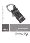
KP 2203
Pinza amperimétrica-vatimétrica
Phase digital power clamp meter
KP 2203
Pinza amperimétrica - vatimétrica
Índice
Precauciones de seguridad
3
Información de seguridad
3
Símbolos de seguridad
3
Descripción general
4
Características
5
Diseño del medidor
6
Utilización del selector
7
Utilización de los botones
7
Pantalla LCD
10
Realización de mediciones
11
Medición de Tensión CA
11
Medición de Corriente CA
13
Medición de circuitos monofásicos
15
Medición de circuitos trifásicos de 4 hilos
19
Medición de circuitos trifásicos de 3 hilos
23
Salvado de las mediciones
24
Recuperación de las mediciones
24
Puerto de Datos RS232C
24
Corriente y Tensión de entrada
24
Retroiluminación de la pantalla
25
Esquema de agarre de seguridad
25
Indicación de batería baja
25
Diagrama de la Curva de Potencia
26
Sustitución de las baterías
27
Especificaciones
28
Contenido de la caja
31
Manual de instrucciones | 2
www.grupotemper.com
KP 2203
Pinza amperimétrica - vatimétrica
Precauciones de
seguridad
Lea estas instrucciones de uso
detenidamente y hasta el final
antes de comenzar a operar con su
medidor. Preste particular atención a
las“ADVERTENCIAS”.
Las instrucciones de estas
advertencias deben ser seguidas.
• Debe tener cuidado cuando se
trabaje con tensiones por encima
de 30V AC. Mantenga los dedos
detrás de las barreras de la
sonda durante la medición.
• Nunca use el medidor para
medir tensiones que pudieran
exceder el máximo valor de
entrada permitido de cualquier
función del modo medición.
• Siempre inspeccione su medidor
y pruebe las puntas antes de
cada uso. Si existiera alguna
condición anómala: pinzas de
prueba rotas, armazón roto,
LCD sin lectura, etc, no intente
realizar ninguna medición.
• Use el medidor y sus pinzas
de prueba siguiendo todas las
normas de seguridad indicadas.
Si necesita cambiar las pinzas
de prueba estropeadas,
reemplácelas por unas del
mismo tipo y especificación
eléctrica.
• No toque nunca una fuente de
tensión cuando las pinzas de
prueba estén enchufadas a una
www.grupotemper.com
•
toma de corriente.
No exponga el aparato a la luz
solar directa, a temperaturas
extremas o a la humedad.
ADVERTENCIA
Lea las instrucciones antes de
utilizar el instrumento.
Información de
seguridad
Esta pinza ha sido diseñada de
acuerdo con las normas IEC1010-1 y
IEC1010-2-03 relativas a las normas
de seguridad de instrumentos
eléctricos de medición. Grado de
contaminación de nivel 2 y categoría
de sobrecarga (600V CATⅢ).
Símbolos de
Seguridad
Información de seguridad
importante, consulte el manual
de instrucciones.
Posible presencia de tensión
peligrosa.
Toma de tierra.
Doble aislamiento (protección
Clase II)).
Pila.
Manual de instrucciones | 3
KP 2203
Pinza amperimétrica - vatimétrica
Descripción general
Esta pinza amperimétrica-vatimétrica
es un medidor portátil de potencia
media, con medidor de corriente
incorporado, el instrumento perfecto
para la medición de energía.
El medidor se compone de tres
canales: tensión, corriente, potencia
y un único chip microcontrolador.
Tiene gran alcance de medición
y software de procesamiento de
datos completo para medir, calcular
y mostrar 8 parámetros: tensión,
corriente, potencia, coeficiente
de potencia, potencia aparente,
potencia reactiva, energía activa y
frecuencia.
Es de fácil uso. Está especialmente
adaptado para la medida y
reacondicionamiento de los equipos
de energía eléctrica y el circuito de
alimentación en campo.
Está diseñado con forma de pinzas,
es muy pequeño, ligero y portátil,
para asegurar una medición fácil y
rápida.
Esta pinza es uno de los mejores
instrumentos para la medición de
circuitos trifásicos.
Manual de instrucciones | 4
www.grupotemper.com
KP 2203
Pinza amperimétrica - vatimétrica
Características
1. Adaptado para la medición de la
potencia del circuitos trifásicos
de tres hilos, trifásicos de cuatro
hilos y circuitos monofásicos.
2. El aparato puede realizar la
medida del verdadero valor
eficaz (RMS). Si no hay señal de
entrada sinusoidal de corriente
alterna puede medir con
precisión la corriente activa.
3. Gracias a su dispositivo de
modo automático del circuito,
módulo del transductor de 8.000
cuentas y alta resolución, hacen
de esta pinza un instrumento
muy exacto y de fácil manejo.
4. La corriente mínima de energía
activa que puede medir es de
0.5A, así mismo puede medir el
gasto de energía por hora de
todos los equipos eléctricos en
general. Medición y visualización
de cinco parámetros de
potencia: potencia activa,
potencia aparente, coeficiente
de potencia, potencia reactiva y
la energía activa.
6. Mide cinco parámetros de
potencia en cada fase y el
valor total de la potencia en
modo de medición trifásico
respectivamente.
7. Botón de control multifuncional,
barra gráfica analógica de
doble escala para mostrar
la fluctuación de corriente y
tensión.
8. Puerto serie PC RS232C y un
software especial gráfico para el
sistema operativo WINDOWS.
9. Pantalla con tiempo de medición
restante y selector de señal
de prueba de tensión que
proporciona potencia a la pinza
al mismo tiempo en modo
de medición de Energía Activa
para una mayor duración de las
mediciones.
10. Pinza amperimétrica portátil,
ligera y fácil de transportar.
5. Su doble pantalla, con dos
parámetros en cada menú,
almacena hasta 28 grupos de
parámetros de medida.
www.grupotemper.com
Manual de instrucciones | 5
KP 2203
Pinza amperimétrica - vatimétrica
Diseño del medidor
1
MAX
1000A
600kW
MAX
600V
CAT.III
DIGITAL POWER CLAMP
HOLD
OFF
EXMR
3
W
7
2
P
3
2
Ture RMS
AUTO RANGE
OFF
kW / PF
kVA
kVAr
kWh
TIME
V / Hz
A
RS232
DC
AC
6
1
1
2
3
CLEAR
W W3
RS232
MAX
PF
MIN
MEM
MR
Hz
kVAr
h min
FREQ
Time
0
20 10
40
MAX
V1
P
kVA
kWh
CAL
V2
20
60
30 80
MIN
V3
40100
SAVE
COM
8
3~
MAX
600V
OPTICAL INTERFACE
4
RS232
Manual de instrucciones | 6
5
1. Pinzas. Ф50mm
2. Botón de retención de datos
(HOLD). Retiene en pantalla el
valor de la lectura, el símbolo
se muestra en la pantalla LCD,
pulsando el botón de nuevo,
el medidor volverá al modo de
medición normal.
3. Selector giratorio de funciones.
Gire el selector a cualquiera de
las funciones de medición.
4. Botones de selección de
funciones. Para seleccionar el
tipo de medición.
5. Tomas de entrada
V1: toma de entrada de la
primera fase, utilice la punta
amarilla de prueba para
conectarse.
V2: toma de entrada para
la segunda fase, utilice la
punta verde de prueba para
conectarse.
V3: toma de entrada para la
tercera fase, utiliza la punta de
prueba roja para conectarse.
COM (común): toma de entrada
de tierra para todos los modos
de medición, utilice la punta de
prueba negra para conectarse.
6. Pantalla LCD. Pantalla LCD
de 4 dígitos y 7 segmentos.
Indicación de valores, modo de
medición y símbolos.
7. Gatillo. Presione el gatillo para
abrir las pinzas transformadoras.
Cuando suelte la palanca, las
pinzas se cerrarán de nuevo.
www.grupotemper.com
KP 2203
Pinza amperimétrica - vatimétrica
8. Puerto de Datos RS232C . La
pinza amperimétrica puede
usar un Cable Puerto Serie
para comunicarse con una
computadora. Dirigirse a la
figura 18 para consultar las
instrucciones completas.
Φ2
SEGUNDO CANAL DE
MEDIDA. Para la toma de
entrada de medida V2.
Φ1
PRIMER CANAL DE
MEDIDA. Para la toma de
entrada de medida V1.
Utilización del selector Utilización de los
botones
Encienda el medidor girando el
selector a cualquier función de las
siguientes.
(Tabla 1. utilización del selector)
POS.
DESCRIPCIÓN
OFF
POWER OFF. Apagado del
medidor.
EX- P
MR
∑W
Φ3
FUENTE DE
ALIMENTACIÓN EXTERNA
Sin consumo de batería,
seleccione una señal de
tensión para la medición
de Energía Activa. Para
mediciones de larga
duración.
RECUPERACIÓN DE
DATOS. Recupera las
mediciones grabadas en
memoria.
(Tabla 2. Botones de función)
BOTÓN
kW / PF
kVA
kVAr
kWh
TIME
Σ
V / Hz
A
POTENCIA TOTAL. Muestra
el valor de la potencia total
trifásica.
RS232
TERCER CANAL DE
MEDIDA. Para toma de
entrada de medida V3.
CLEAR
www.grupotemper.com
Nº
DESCRIPTION
1
Potencia activa,
botón de medida
de coeficiente de
potencia
2
Botón de medida de
potencia aparente y
de potencia reactiva
3
Botón de medición
de energía activa
por unidad de
tiempo
4
Sumatorio de
potencia
5
Medición de la
frecuencia del
voltaje
6
Botón de medida de
corriente.
7
Botón de
transmisión de
datos
8
Botón de borrado
de memoria
Manual de instrucciones | 7
KP 2203
Pinza amperimétrica - vatimétrica
9
Botón de
retroiluminación
MAX
10
Botón de máximo
valor/ Botón de
grabado previo
MIN
11
Botón de valor
mínimo/ Botón de
grabado siguiente
12
Botón de salvado de
datos
SAVE
1.
2.
kW / PF Potencia activa, botón
de medida del coeficiente de
potencia.
Presione el botón kW / PF para
la medida de potencia activa
y del coeficiente de potencia.
El LCD mostrará los datos
leídos de potencia activa en la
pantalla primaria y el coeficiente
de potencia en la pantalla
secundaria.
3.
4.
kVA
kVAr
Botón de medida
de Potencia aparente y de
Potencia reactiva.
kVA
Presione el botón kVAr
para
medir la potencia aparente
y la potencia reactiva. El LCD
mostrará ,los datos leídos
de potencia aparente en la
pantalla primaria y los de
potencia reactiva en la pantalla
secundaria.
Manual de instrucciones | 8
5.
kWh
TIME
Botón de medición de
energía activa por unidad de
tiempo.
kWh
Presione el botón TIME
para medir la energía activa.
El LCD mostrará los datos
leídos de energía activa en la
pantalla primaria y el tiempo
de medición de la misma en la
pantalla secundaria.
Σ
Sumatorio de
potencia.
Σ
Presione el botón
para
sumar los valores medidos de
la corriente fase 1 en modo
trifásico; luego mida la fase 2 y
Σ
presione el botón
para
sumar otra vez; presione el
Σ
botón
para la tercera fase
después de conseguir el valor
de medición de la tercera fase
en la pantalla. Así el medidor
calculará la suma de este sistema
trifásico automáticamente. Gire
el selector hacia ∑W entonces
la pantalla mostrará el total del
valor de la potencia.
V / Hz
Botón de medición de
la frecuencia del voltaje.
Presione el botón V / Hz para
medir la frecuencia del circuito y
mostrar los valores leídos en la
pantalla LCD.
www.grupotemper.com
KP 2203
Pinza amperimétrica - vatimétrica
6.
7.
A
Botón de medida de
corriente.
A
Presione el botón
para
medir la corriente del circuito
y mostrar los valores leídos en
pantalla LCD.
10.
RS232
Botón de transmisión
de datos.
Presione el botón RS232
para trasmitir las mediciones
al ordenador. Mediante un
cable especial, puede grabar el
valor de la corriente medida e
imprimir un gráfico de la curva
de tendencia de datos.
Antes de presionar el botón
RS232 debe conectar el cable
puerto RS232C a la pinza
amperimétrica y al ordenador
para activar la comunicación.
8.
CLEAR Botón de borrado de
memoria.
Presione el botón CLEAR
durante tres segundos para
borrar todos los datos salvados
en la memoria de la pinza.
9.
Botón de
retroiluminación.
Presione el botón
para encender o apagar la
retroiluminación. Cuando la
retroiluminación esté activada
durante más de cinco segundos
se apagará automáticamente.
www.grupotemper.com
11.
12.
MAX
Botón de máximo
valor/ Botón de grabado previo.
Presione el botón MAX para
medir el valor máximo en modo
medición. El LCD mostrará el
valor de la corriente máxima en
la pantalla secundaria.
Cuando gire el selector a la
posición MR presione el botón
MAX
para recuperar datos
grabados previamente. Vuelva
a pulsarlo para recuperar datos
grabados en posiciones de
memoria previas.
MIN
Botón de valor
mínimo/ Botón de grabado
siguiente.
MIN
Presione el botón
para
medir el valor mínimo en modo
medición. El LCD mostrará el
valor de la corriente máxima en
la pantalla secundaria.
Cuando gire el selector a la
posición MR presione el botón
MIN
para recuperar datos
grabados previamente. Vuelva
a pulsarlo para recuperar datos
grabados en posiciones de
memoria anteriores.
SAVE
Botón de salvado de
datos.
Presione el botón SAVE para
salvar los datos de la corriente
leída. El medidor puede salvar
hasta 28 grupos de datos.
Manual de instrucciones | 9
KP 2203
Pinza amperimétrica - vatimétrica
Pantalla LCD
1.
2.
3.
4.
5.
6.
7.
8.
9.
Tensión peligrosa
Mantenimiento de datos
Primera fase
Segunda fase
Tercera fase
Potencia total trifásica
Alimentación externa
Indicador de batería
Unidad de tensión (V), unidad
de corriente (A), unidad de
potencia aparente (kVA) (pantalla
primaria)
10. Unidad de potencia activa (kW),
unidad de energía activa (kWh)
11. Pantalla de 4 dígitos (pantalla
primaria)
12. Unidad de frecuencia
13. Unidad de tensión (V), unidad
de corriente (A), unidad de
potencia aparente (kVA), unidad
de potencia reactiva (kVAr)
(pantalla secundaria)
14. Unidad de tiempo: horas(h),
minutos (min)
Manual de instrucciones | 10
15. Símbolo de sobrecarga
16. Escala graduada a 100
17. Escala graduada a 40
18. Gráfico de barra
19. Pantalla de 4 dígitos (pantalla
secundaria)
20. Unidad de frecuencia
21. Tiempo
22. Símbolo negativo de la escala
23. Número de localización en la
memoria
24. Símbolo de recuperación de
datos
25. Símbolo de salvado de datos
26. Símbolo de valor mínimo
27. Símbolo del coeficiente de
potencia
28. Símbolo de valor máximo
29. Símbolo puerto RS232C
30. Símbolo de calibrado
31. Símbolo negativo
32. Símbolo CA
33. Símbolo CC
www.grupotemper.com
KP 2203
Pinza amperimétrica - vatimétrica
Realización de mediciones
Medición de la tensión CA
1
V
AC
MAX
1000A
600kW
MAX
600V
CAT.III
MEM
0
20
40
60
80
Circuit
AC V
Hz
FREQ
Circuito
V1
HOLD
100
OFF
EX -
P
MR
W
3
2
Ture RMS
AUTO RANGE
1
1
kW / PF
V
AC
V / Hz
OFF
kVA
kVAr
kWh
TIME
A
RS232
CLEAR
1
V
AC
Hz
FREQ
Hz
FREQ
MEM
0
MEM
10
MAX
0
10
20
30
40
V1
V2
20
30
MIN
V3
40
SAVE
COM
Negro
Black
Amarillo
Yellow
(Figura 3. Mediciones de voltaje)
1. Gire el selector hacia una de las
posiciones Φ1, Φ2, Φ3, consulte
la tabla 3 para conectar las
puntas de prueba a las tomas
de entrada: inserte la punta de
prueba negra en la toma COM y
y la punta de prueba en su toma
correspondiente según color.
(Figura 3 )
(Tabla 3 Conexiones de las tomas)
Selector
TERMINAL
ENTRADA(+)
TERMINAL
ENTRADA(-)
Fase
Φ1
Toma
V1
Punta
amarilla
COM jack
Punta
negra
Primera fase
Φ2
Toma
V2
Punta verde
COM jack
Punta
negra
Segunda fase
Φ3
Toma
V3
Punta roja
COM jack
Punta
negra
Tercera fase
www.grupotemper.com
Manual de instrucciones | 11
KP 2203
Pinza amperimétrica - vatimétrica
mostrará el símbolo“MIN, el
valor mínimo (TRMS) aparecerá
en la pantalla secundaria.
MIN
Presiones el botón
de
nuevo, el símbolo “MIN”
desaparecerá y la pantalla
secundaria volverá al valor de
frecuencia de corriente.
5. Cuando la entrada de tensión
exceda los 600V, la pantalla
mostrará el símbolo“OL”y la
barra del gráfico se mostrará
completa. (Figura 4).
6. Cuando la entrada de tensión
exceda los 30V, la pantalla
mostrarará el símbolo
de
seguridad.
7. Existen dos maneras de mostrar
2. Conecte las puntas de prueba
a la carga, presione el botón
V / Hz y el valor medido se
mostrará en la pantalla primaria
y el valor de la frecuencia de
corriente de tensión en la
pantalla secundaria.
3. En el modo medición de tensión,
presione el botón MAX , el LCD
mostrará el símbolo“MAX”, el
máximo valor (TRMS) aparecerá
en la pantalla secundaria.
Presione el botón MAX de
nuevo, el símbolo “MAX”
desaparecerá y la pantalla
secundaria volverá al valor de
frecuencia de corriente.
MIN
4. Presione el botón
, el LCD
MAX
1000A
600kW
MAX
600V
CAT.III
Circuito
Circuit
AC V
V1
HOLD
OFF
EX -
P
MR
W
3
2
Ture RMS
AUTO RANGE
1
1
V
AC
kW / PF
V / Hz
OFF
kVA
kVAr
kWh
TIME
A
RS232
CLEAR
1
Hz
FREQ
V
AC
Hz
FREQ
MEM
0
MEM
10
MAX
0
20
40
60
80
100
V1
V2
20
30
MIN
V3
40
SAVE
COM
Negro
Black
Amarillo
Yellow
(Figura 4. Tensión que supera los 600V)
(Figura 4. Entrada de tensión superior a 600V)
Manual de instrucciones | 12
www.grupotemper.com
KP 2203
Pinza amperimétrica - vatimétrica
la barra gráfica en el
LCD. Puede observar la
fluctuación de la medida
en la escala de tensión. El
primer modo es 0-20-40-6080-100, el segundo modo es
0-10-20-30-40.
1
Tested
conductor
Conductor
2
3
MAX
600V
CAT .I II
MAX
1000A
600kW
hilo de
Earth
wireneutro
HO LD
O FF
EX -
P
MR
W
3
3
A
AC
RS232
Ture RMS
AUTO RANGE
2
1
kW / PF
kV A
kV Ar
V / Hz
A
O FF
kWh
TIME
RS232
CLEAR
3
A
AC
RS2 32
MEM
MEM
0
10
20
30
0
40
10
MAX
V1
V2
20
30
MIN
V3
40
SAVE
COM
(Figure 5. Mediciones de corriente)
Medición de corriente CA
1. Gire el selector a una de las
posiciones Φ1, Φ2, Φ3.
2. Presione el gatillo para
enganchar la pinza alrededor
del conductor a medir. Presiones
A
el botón
, la pantalla
primaria leerá el valor de la
corriente (RMS) del conductor.
(Figura 5)
www.grupotemper.com
3. Para medir el valor máximo
de la corriente presione el
botón MAX , el valor máximo
se mostrará en la pantalla
secundaria. Presione el botón
MAX
de nuevo para cancelar
la medición del valor máximo.
(Figura 6)
4. Para medir el valor mínimo
de la corriente presione el
MIN
botón
, el valor mínimo
Manual de instrucciones | 13
KP 2203
Pinza amperimétrica - vatimétrica
se mostrará en la pantalla
secundaria. Presione el botón
MIN
de nuevo para cancelar la
medición del valor mínimo.
5. Cuando la corriente exceda
los 1000A (RMS), la pantalla
mostrará el símbolo“OL”.
(Figura 7).
6. Existen dos maneras de mostrar
la barra gráfica en el LCD. Puede
observar la fluctuación de la
medida en la escala de corriente.
El primer modo es 0-20-40-6080-100, el segundo modo es
0-10-20-30-40. (Figuras 5 y 6).
1
2
Tested conductor
fase
3
MAX
1000A
600kW
MAX
600V
CAT.I II
Earth
wire
neutro
HOLD
OFF
3
EX-
P
MR
A
AC
A
MAX
MEM
W
3
Ture RMS
AUTO RANGE
2
1
OFF
kW / PF
kVA
kVAr
kWh
TIME
V / Hz
A
RS232
CLEAR
3
0
20
40
60
80
100
A
AC
MAX
A
MEM
0
20
MAX
V1
V2
40
60
MIN
V3
80
100
SAVE
COM
(Figura 6. Mediciones de máximo valor de la corriente)
Manual de instrucciones | 14
www.grupotemper.com
KP 2203
Pinza amperimétrica - vatimétrica
1
2
Conductor
medido
Tested conductor
3
MAX
1000A
600kW
MAX
600V
CAT.I II
Hilo de
Earth
wireneutro
HOLD
OFF
EX -
3
P
MR
W
A
AC
3
2
Tur e RMS
AUTO RANGE
1
OFF
kW / PF
kVA
kVAr
kWh
TIME
V / Hz
A
RS232
CLEAR
3
MEM
A
AC
0
20
40
60
80
100
RS232
MEM
0
20
40
60
MAX
V1
80
MIN
V2
100
SAVE
COM
V3
(Figura 7. Corriente superior a 1000A)
Medición de circuitos monofásicos
(Figura 8. Mediciones de
potencia monofásicas)
Conductor
medido
Tested conductor
MAX
1000A
600kW
MAX
600V
CAT.I II
Cable
de tierra
Earth wire
HOLD
OFF
EX - P
MR
W
3
Ture RMS
AUTO RANGE
2
1
2
AC
kW
OFF
kW / PF
kVA
kVAr
kWh
TIME
V / Hz
A
RS232
CLEAR
2
AC
kW
PF
PF
MEM
0
MEM
20
MAX
0
20
40
60
80
100
V1
V2
40
60
MIN
V3
80
100
SAVE
COM
Negro
Black
www.grupotemper.com
Verde
Green
Manual de instrucciones | 15
KP 2203
Pinza amperimétrica - vatimétrica
1. Coloque las pinzas del medidor
alrededor del conductor, de la
carga o del circuito.
2. Coloque el selector en una de
las posiciones Φ1, Φ2, Φ3, y
consulte la tabla 3 para conectar
las puntas de prueba a las tomas
de entrada que se correspondan
con la posición del selector.
(Figura 8).
3. Tras una conexión correcta,
podrá medir cinco parámetros
de potencia de un circuito de
monofásico (potencia activa,
coeficiente de potencia, potencia
aparente, potencia reactiva,
energía activa):
(1.) Potencia activa (kW) y
coeficiente de potencia (PF)
(Figura 8 )
a. Presiones el botón kW / PF
, el valor de potencia activa
se mostrará en la pantalla
primaria y el coeficiente
de potencia y el símbolo
“PF”se mostrarán en la
pantalla secundaria. Cuando
el coeficiente de potencia es
negativo la carga es capacitiva.
b. El rango de medida máximo
de la potencia activa es de
600kW. Si se excede el valor
máximo, el símbolo “OL”
aparecerá en la pantalla.
Si la prueba de tensión
excede los 600V o el test de
corriente excede los 1000A,
el símbolo“OL” también
Manual de instrucciones | 16
se mostrará en la pantalla y
la barra gráfica se mostrará
completa. La entrada mínima
de tensión es de 20V y la
entrada mínima de corriente
de 5A, por debajo de estos
valores la potencia activa
mostrada será “0.00kW”.
MAX
c. Presione el botón
button, el valor máximo de
potencia activa se mostrará en
la pantalla secundaria.
MIN
d. Presione el botón
,
el valor mínimo de la potencia
activa se mostrará en la
pantalla secundaria.
e.La barra gráfica mostrará
alguno de los valores
“0-20-40-60-80-100”
correspondientes a la potencia
medida.
www.grupotemper.com
KP 2203
Pinza amperimétrica - vatimétrica
Conductor
medido
Tested conductor
MAX
1000A
600kW
MAX
600V
CAT.I II
Hilo
dewire
neutro
Earth
HOLD
OFF
EX-
P
MR
W
3
Ture RMS
AUTO RANGE
2
1
2
AC
kW
OFF
kW / PF
kVA
kVAr
kWh
TIME
V / Hz
A
RS232
CLEAR
2
AC
kW
PF
PF
MEM
0
MEM
20
MAX
0
20
40
60
80
100
V1
V2
40
60
MIN
V3
80
100
SAVE
COM
Black
Negro
Verde
Green
(Figura 9. Corriente que excede los 1000A o tensión que excede los 600V)
(2.) Potencia aparente (kVA) y
potencia reactiva (kVAr)
kVA
a. Presione el botón kVAr
, la potencia aparente se
mostrará en la pantalla
primaria; el valor de la
potencia reactiva y la barra
gráfica “0-20-40-60-80-100”
en la pantalla secundaria.
(Figura 10)
b. Para entradas de tensión
menores de 20V y entradas
de potencia menores de 5A, el
valor de la potencia aparente
mostrado será “0.00kVA”.
c. Presione el botón MAX ,
el valor máximo de la potencia
www.grupotemper.com
aparente se mostrará en la
pantalla secundaria.
MIN
d. Presione el botón
,
el valor mínimo de la potencia
aparente se mostrará en la
pantalla secundaria.
e. La potencia reactiva no
es un parámetro de medida
de potencia directo, La
fórmula para calcular el valor
de la potencia reactiva es
kVAr2=kVA2-kW2. El valor
es calculado y mostrado de
acuerdo con la tensión, la
corriente y la potencia activa
mediante software.
Manual de instrucciones | 17
KP 2203
Pinza amperimétrica - vatimétrica
Conductor
medido
Tested conductor
MAX
1000A
600kW
Hilo
neutro
Earthde
wire
MAX
600V
CAT.I II
HOLD
OFF
EX -
P
MR
W
3
Ture RMS
AUTO RANGE
2
1
3
kVA
AC
kW / PF
kVA
kVAr
V / Hz
A
OFF
kWh
TIME
RS232
CLEAR
3
kVA
AC
kVAr
kVAr
MEM
0
MEM
20
MAX
0
20
40
60
80
100
V1
V2
40
60
MIN
V3
80
100
SAVE
COM
Negro
Black
Rojo
Red
(Figura 10. Mediciones de potencia aparente)
(3.) Energía activa (kWh) y
tiempo (hmin)
a. En el modo de medición de
energía activa, la señal de la
tensión debe estar en la toma
V1 y en la toma COM de la
pinza amperimétrica (Figura
11), y el selector debe estar en
la posición Φ1. De este modo
la medición de la energía
activa será válida.
kWh
b. Presione el botón TIME
, para que valor de salida
de la energía Activa sea de
“0.000kWh” y se muestre
en la pantalla primaria. El
tiempo de medición de la
energía activa y el gráfico de
Manual de instrucciones | 18
barra “0-20-40-60-80-100”
aparecerán en la pantalla
secundaria. Si necesita leer
el valor de la energía activa
en algún momento, presione
el botón HOLD, así el valor
medido mostrado y el tiempo
se bloquearán, sin embargo
en la pinza amperimétrica la
medición de la energía activa
y el tiempo continuará. Tras
leer la pantalla presione el
botón HOLD otra vez para
salir y continuar la medición,
la medición de la energía
activa continuará hasta que
se seleccione otra función de
medida.
www.grupotemper.com
KP 2203
Pinza amperimétrica - vatimétrica
c. Los botones MAX y
MIN
están innactivos en
este modo de medición.
d. El valor máximo de
la energía activa es de
“9999kWh”. Si la energía
activa excede este valor
máximo , la pantalla mostrará
el símbolo “OL”.
e. La medición de la energía
activa es viable en circuitos
monofásicos porque sólo se
mide corriente de una fase
de cada vez, así que no se
puede medir energía activa
trifásica. Si necesita medir
energía activa durante un
largo periodo de tiempo, le
sugerimos que use la función
EX- P, el medidor funcionará
sin consumo de batería
con fuente de alimentación
externa.
AVISO: Cuando gire el selector
a la posición EX- P para medir
la tensión o el parámetro de
potencia, la entrada de tensión V1
debe ser menor de 250V, de otro
modo el fusible se fundirá.
www.grupotemper.com
Medición de circuitos
trifásicos de 4 hilos
Parámetro de potencia trifásico
significa potencia activa total,
potencia reactiva total, potencia
aparente total, el coeficiente
de potencia total. La pinza
amperimétrica no puede medir la
energía activa trifásica. El proceso
de medición de parámetros de
potencia trifásicos indica que
mida primero el parámetro de
potencia de cada del conductor
respectivamente, y luego calcule
el parámetro de potencia trifásico
con el medidor. Para un balance de
la carga, la medición de los datos
debe ser precisa, si la fluctuación del
parámetro de potencia es amplia, el
error del parámetro de potencia total
aumentará.
1. Consulte la Tabla 3, conecte
las puntas de prueba amarilla,
verde, y roja a todas las líneas
vivas del circuito trifásico y
a las tomas V1, V2, V3 del
instrumento respectivamente.
Conecte la punta de prueba
negra al cable neutro del
circuito y a la toma COM del
medidor.
2. Primero, gire el selector hacia
la posición Φ1 (medición de
la primera fase), coloque las
pinzas del medidor alrededor
del conductor de la primera fase
del circuito a medir, presione
Manual de instrucciones | 19
KP 2203
Pinza amperimétrica - vatimétrica
(Figura 12).
3. Gire el selector a la posición
Φ2 (medición de la segunda
fase), coloque las pinzas del
medidor alrededor de conductor
de la segunda fase del circuito
a medir, presione los botones
kVA
kW / PF y
para medir
kVAr
los parámetros de potencia
respectivos, cuando aparezcan
los resultados presione el botón
Σ
para añadirlos al cálculo.
La operación es similar a la
medición en la primera fase.
(Figura 13)
el botón kW / PF para medir
la potencia activa (kW) y el
coeficiente de potencia (PF). El
valor medido se mostrará en
la pantalla LCD, a continuación
Σ
presiones el botón
para
añadir el parámetro de potencia
de esta fase; presione el botón
kVA
para medir la potencia
kVAr
aparente y la potencia reactiva,
tras lo cual el resultado se
mostrará en el LCD, presione
el botón
para añadir
Σ
el parámetro de potencia de
esta fase. Así, la medición del
parámetro de potencia estará
completo en esta primera fase.
Si necesita guardar el resultado,
presione el botón SAVE
..(Figura 12)
Tested conductor
Conductor
medido
MAX
1000A
600kW
MAX
600V
CAT.III
2
3
1
HOLD
OFF
EX -
AC
P
Hilo de
Earth
wireneutro
MR
W
kW
3
Ture RMS
AUTO RANGE
PF
kW / PF
V / Hz
MEM
0
1
20
40
60
80
2
1
OFF
kVA
kVAr
kWh
TIME
A
RS232
CLEAR
100
1
AC
kW
PF
MEM
0
1
20
MAX
V1
kVA
AC
V2
40
60
MIN
V3
80
100
SAVE
COM
Negro Rojo
Verde
Amarillo
Black Red Green Yellow
kVAr
MEM
0
20
40
60
80
100
(Figura 12. Medición de la primera fase)
Manual de instrucciones | 20
www.grupotemper.com
KP 2203
Pinza amperimétrica - vatimétrica
1
Tested conductor
Conductor medido
MAX
1000A
600kW
2
MAX
600V
CAT.III
3
Earth wire
HOLD
2
Hilo de neutro
OFF
EX -
P
MR
AC
W
kW
PF
3
2
Ture RMS
AUTO RANGE
1
kVA
kVAr
kWh
TIME
V / Hz
A
RS232
MEM
0
20
40
60
80
100
OFF
kW / PF
CLEAR
2
AC
kW
PF
MEM
0
20
MAX
2
V1
V2
kVA
AC
40
60
MIN
V3
80
100
SAVE
COM
Black Red Green Yellow
Negro Rojo
Verde
Amarillo
kVAr
MEM
0
20
40
60
80
100
(Figure 13. Mediciones de la segunda fase)
4. Gire el selector a la posición Φ3
(medición de la tercera fase),
coloque las pinzas del medidor
alrededor de conductor de
la segunda fase del circuito a
medir, presione los botones
kVA
kW / PF y
para medir
kVAr
los parámetros de potencia
respectivos, cuando aparezcan
los resultados presione el botón
Σ
para añadirlos al cálculo.
La operación es similar a la
medición en la primera fase.
(Figura 14)
5. Tras la medición de cada
fase coloque el selector en
la posición ∑W, la pantalla
www.grupotemper.com
mostrará el t valor total de la
potencia activa y el valor del
coeficiente de potencia de
la carga trifásica (Figura 15).
Tras mostrarse durante tres
segundos, la pantalla cambiará
automáticamente para mostrar
el valor de la potencia total
aparente y el valor de la potencia
reactiva total (Figura 16) en la
pantalla primaria y secundaria
respectivamente. La pantalla
cambia automáticamente cada
tres segundos hasta que se
seleccione otra función de
medición.
Manual de instrucciones | 21
KP 2203
Pinza amperimétrica - vatimétrica
(Figura 14. Mediciones de
la potencia trifásica)
1
Conductor
medido
Tested
conductor
2
3
MAX
1000A
600kW
MAX
600V
CAT.I II
Hilo
Earthde neutro
HOLD
3
OFF
EX - P
MR
AC
W
kW
3
Ture RMS
AUTO RANGE
PF
2
1
kVA
kVAr
kWh
TIME
V / Hz
A
RS232
MEM
0
20
40
60
80
OFF
kW / PF
CLEAR
3
100
AC
kW
PF
MEM
0
3
20
MAX
V1
V2
40
60
80
MIN
100
SAVE
COM
V3
kVA
AC
Negro
Verde Amarillo
Black Rojo
Red Green
Yellow
kVAr
MEM
0
(Figura 14. Mediciones de potencia de la tercera fase)
20
40
60
80
100
(Figura 15. Potencia
total activa trifásica)
1
2
Tested
conductor
Conductor
medido
3
Hilo de neutro
Earth wire
MAX
1000A
600kW
MAX
600V
CAT.I II
HOLD
OFF
EX -
P
MR
W
3
Ture RMS
AUTO RANGE
1
2
3
2
1
W
kVA
kVAr
kW / PF
AC
A
V / Hz
kW
1
2
OFF
kWh
TIME
RS232
3
CLEAR
W
AC
kW
PF
PF
MEM
0
MEM
20
MAX
0
20
40
60
80
100
V1
V2
40
60
MIN
V3
80
100
SAVE
COM
Negro Rojo
Verde
Amarillo
Black Red Green Yellow
(Figura 15. Potencia activa trifásica total)
Manual de instrucciones | 22
www.grupotemper.com
KP 2203
Pinza amperimétrica - vatimétrica
(Figura 16. Potencia
aparente total
trifásica)
1
2
Tested
conductor
Conductor
medido
3
MAX
1000A
600kW
Earth wire
Hilo de neutro
MAX
600V
CAT.III
HOLD
OFF
EX-
P
MR
W
3
Ture RMS
AUTO RANGE
1
2
3
2
1
W
kVA
AC
OFF
kW / PF
kVA
kVAr
kWh
TIME
V / Hz
A
RS232
1
2
3
CLEAR
W
kVA
AC
kVAr
kVAr
PF
MEM
0
MEM
20
MAX
0
20
40
60
80
100
V1
V2
40
60
MIN
V3
80
100
SAVE
COM
Negro Rojo
Verde
Amarillo
Black Red Green Yellow
Medición de circuitos
trifásicos de 3 hilos
La medición en circuitos trifásicos
de tres hilos es similar a la de cuatro
hilos excepto por la conexión de las
puntas de prueba. (Figura 17)
1
MAX
1000A
600kW
MAX
600V
CAT.III
Conductor
medido
Tested
conductor
1
HOLD
2
3
OFF
EX - P
AC
MR
W
kW
3
2
Ture RMS
AUTO RANGE
PF
MEM
0
20
40
60
80
1
OFF
kW / PF
kVA
kVAr
kWh
TIME
V / Hz
A
RS232
CLEAR
100
1
AC
kW
PF
MEM
0
20
MAX
V1
(Figura 17. Medición de potencia
en cisrcuitos trifásicos de tres
hilos)
www.grupotemper.com
V2
40
60
MIN
V3
80
100
SAVE
COM
Rojo Verde Amarillo
Red Green Yellow
Manual de instrucciones | 23
KP 2203
Pinza amperimétrica - vatimétrica
Salvado de las mediciones
En modo medición, presione el
botón SAVE para guardar los
datos actuales de la pantalla en una
posición de memoria. El medidor
puede almacenar hasta 28 grupos de
datos.
Cuando el medidor haya guardado
28 grupos de datos, si presiona
el botón SAVE para guardar
de nuevo, la pantalla mostrará el
símbolo “FUL” que anuncia que la
memoria se encuentra llena. Presione
para limpiar la memoria y
CLEAR
continuar guardando.
Recuperación de las
mediciones
Para recuperar los datos guardados
en la memoria del medidor, siga las
siguientes instrucciones:
1. Gire el selector hacia la posición
MR.
2. La pantalla mostrará el símbolo
“MR” y el símbolo “HOLD”,
el número de localización y
datos guardados en la posición
de memoria actual.
3. Utilice los botones MAX y
MIN
para navegar por las
posiciones de memoria.
Puerto de Datos RS232C
como se muestra en la figura 18,
luego gire el cable para fijarlo al
medidor. Conecte el otro extremo
del cable a un Puerto serie de
un ordenador. El medidor podrá
transmitir los datos al ordenador por
medio de fotoelectricidad infrarroja
al puerto RS232C en modo tiempo
real. Para quitar el cable de la pinza,
vuelva a girarlo para desbloquearlo y
extraerlo.
Instale el software especial de
grabación en su computadora
siguiendo las instrucciones del
archivo README.TXT del disco de
instalación. Cuando el medidor
esté en modo medición, presione
el botón RS232 para grabar e
imprimir las mediciones en tiempo
real. Este software puede grabar,
trazar e imprimir los datos y gráficas
recogidos por el medidor.
Corriente y Tensión de
entrada
Cuando el medidor está en modo
medición de potencia, si la entrada
de tensión excede los 600V (TRMS)
o la corriente excede los 1000A
(TRMS), la pantalla mostrará el
símbolo “OL” , y la barra gráfica
se mostrará completa. Cuando la
entrada de tensión exceda los 30V,
aparecerá el símbolo
en pantalla
como medida de seguridad.
Conecte el cable RS232C a la pinza
Manual de instrucciones | 24
www.grupotemper.com
KP 2203
Pinza amperimétrica - vatimétrica
3~
M AX
600V
O P T IC A L IN T E R F A C E
R S232
PC
R S 2 3 2 -C
O P T IC A L
IN T E R F A C E
(Figure 18. Conexión del cable RS232C)
Retroiluminación de la
pantalla
Presione el botón
para
encender la retroiluminación de la
pantalla LCD. Tras 4 segundos se
apagará automáticamente.
de tensión como proveedor de
potencia externa para funcionar.
Mediante este sistema, el medidor
solo podrá medir circuitos
monofásicos y no podrá funcionar en
circuitos trifásicos.
Esquema de agarre de
seguridad
Use la correa de muñeca para evitar
que se le resbale accidentalmente, tal
como se muestra en la figura 19.
Indicación de batería baja
Si aparece el símbolo
en la parte
superior derecha de la pantalla
deberá sustituir las pilas o utilizar
la función EX-P del medidor. Gire
el selector a la posición EX- P , y el
medidor usará la señal de medición
www.grupotemper.com
(Figure 19)
Manual de instrucciones | 25
KP 2203
Pinza amperimétrica - vatimétrica
Diagrama de la Curva de Potencia
(PF=KW / KVA)
2000W
+E
+I
+P
(Figura 20. PF=1)
2000W
PEAK VALUE OF POWER
E
MAX
=141V
PEAK VALUE
1000W
-E
-I
-P
ACTIVE POWER
POWER
180°
90°
I
MAX
360°
X
=14A
PEAK VALUE
(Figura 21)
+V
+I
+P V
P
MAX
I
MAX
500W
ACTIVE POWER
KW=I R
2
X
45°
-E
-I
-P
90°
180°
θ
PEAK VALUE
45°
270°
225°
360°
θ
45°
(Figura 22)
+V
+I
+P
P
V
MAX
+V
+i
I
MAX
kW= I R
2
180°
-E
-I
-P
Manual de instrucciones | 26
θ
θ
X
-i
360°
-V
www.grupotemper.com
KP 2203
Pinza amperimétrica - vatimétrica
Sustitución de las
baterías
PRECAUCIÓN
Para evitar descargas
eléctricas, el aparato debe
estar apagado y las puntas
de prueba desconectadas de
fuente de alimentación antes
de cambiar las baterías. Nunca
use el aparato a menos que
la tapa trasera del mismo
esté completamente cerrada.
Sustituya las baterías por unas
del mismo tipo o clasificación.
Cuando la pantalla LCD muestre
el símbolo
debe sustituir las
baterías para mantener el correcto
funcionamiento. Utilice el siguiente
procedimiento para la sustitución de las
mismas:
1. Desconecte las puntas de
prueba de cualquier fuente de
alimentación, gire el selector
a la posición OFF, y retire las
puntas de prueba delas tomas
de entrada.
2. Abra la tapa de las baterías
y retírela. No fuerce la tapa
de apertura o se romperá.
Consulte la figura 23 para abrirla:
Introduzca una moneda en la
ranura de la tapa, presione con
la moneda hacia abajo, y abra la
tapa.
3. Quite las pilas y sustitúyalas por
unas nuevas del mismo tipo o
clasificación.
4. Vuelva a colocar la tapa.
(Figura 23)
www.grupotemper.com
Manual de instrucciones | 27
KP 2203
Pinza amperimétrica - vatimétrica
Especificaciones
VOLTAJE CA
VALOR EFICAZ (RMS)
RANGO
PRECISION
RESOLUCION
IMPEDANCIA DE ENTR.
100V
±(1.2%+5)
0.1V
300V
±(1.2%+5)
0.1V
10 MΩ
(DERIVACIÓN 10Pf)
600V
±(1.2%+5)
0.1V
Límite de sobrecarga: 750V (RMS)
CORRIENTE AC
RMS
RANGO
PRECISION
RESOLUCION
40A
±(2%+5)
0.1A
100A
±(2%+5)
0.1A
400A
±(2%+5)
0.1A
1000A
±(2%+5)
0.1A
Límite de sobrecarga: 1500A
POTENCIA ACTIVA
(W)
RANGO
PRECISION
RESOLUCION
4kW
±(3%+5)
0.01kW
10kW
±(3%+5)
0.01kW
40kW
±(3%+5)
0.01kW
100kW
±(3%+5)
0.01kW
600kW
±(3%+5)
0.1kW
Corriente mínima de medición: 5A
Voltaje mínimo de medición: 20V
Manual de instrucciones | 28
www.grupotemper.com
KP 2203
Pinza amperimétrica - vatimétrica
POTENCIA APARENTE
(VA)
RANGO
PRECISION
RESOLUCION
4kVA
±(3%+5)
0.01kVA
10kVA
±(3%+5)
0.01kVA
40kVA
±(3%+5)
0.01kVA
100kVA
±(3%+5)
0.01kVA
600kVA
±(3%+5)
0.1kVA
Corriente mínima de medición: 5A
Voltaje mínimo de medición: 20V
COEFICIENTE DE POTENCIA
(PF)
0.3~1 Capacitiva
±(0.02+2)
0.001
0.3~1 Inductiva
±(0.02+2)
0.001
10kVA
±(3%+5)
0.01kVA
Corriente mínima de medición: 5A
Voltaje mínimo de medición: 20V
POTENCIA REACTIVA
Q(KVAr)= UI Sin φ
RANGO
PRECISION
RESOLUCION
4kVAr
±(4%+5)
0.01kVAr
10kVAr
±(4%+5)
0.01kVAr
40kVAr
±(4%+5)
0.01kVAr
100kVAr
±(4%+5)
0.01kVAr
600kVAr
±(4%+5)
0.1kVAr
Corriente mínima de medición: 5A
Voltaje mínimo de medición: 20V
Al grabar el valor de voltaje, valor de corriente, valor de potencia activa para
calcular el valor de la potencia reactiva, la precisión del cálculo es de 0.01%
de la escala.
www.grupotemper.com
Manual de instrucciones | 29
KP 2203
Pinza amperimétrica - vatimétrica
ENERGÍA ACTIVA
(kWh)
RANGO
PRECISIÓN
RESOLUCIÓN
1~9999kWh
±(3%+2)
0.001kWh
Corriente mínima de medición: 0.5A
Voltaje mínimo de medición: 10V
FREQUENCY
( Hz )
RANGE
PRECISIÓN
RESOLUCIÓN
20Hz~1kHz
0.5%
0.1Hz
Voltaje mínimo de medición: 20V
•
•
•
•
•
•
•
•
•
•
•
Precisión: % de lectura + número de dígitos.
La especificación dada conlleva una temperatura para operar: de 18℃
~28℃, hasta un 80% de humedad y una frecuencia de tensión y de
corriente entre 45Hz~65Hz
Tensión máxima mas común: 600V AC RMS
Pantalla: LCD 9999
Escala: automática
Indicación de sobrecarga: símbolo “OL”en pantalla
Pilas: 4× 1.5V AA
Consumo de energía: 250mW
Temperatura de almacenaje: -20℃~70℃
Temperatura de funcionamiento: 0℃~40℃
Dimensiones: 300mm×103mm×51mm
Peso: 500g aprox. (incluidas las baterías)
Manual de instrucciones | 30
www.grupotemper.com
KP 2203
Pinza amperimétrica - vatimétrica
Contenido de la caja
Manual de usuario
1
Baterías, 1.5V AA
4
Puntas de prueba (MS3000)
1
Pinza amperimétrica (MS3102)
1
Cable RS232C ( MS3403 )
1
Software de registro gráfico de datos
1
Maletín
1
www.grupotemper.com
Manual de instrucciones | 31
KP 2203
Phase digital power clamp meter
Contents
Safety Precautions
33
Safety Information
33
Safety Symbols
33
General Description
34
Features
35
Meter Layout
36
Using The Selector
37
Using The Buttons
37
Lcd Display
40
Making Measurements
41
Measuring AC Voltage
41
Measuring AC Current
43
Measuring Single-Phase Circuit
45
Measuring Three -Phase Four-Wire Circuit
49
Measuring Three -Phase Three-Wire Circuit
53
Saving Measurement
54
Recalling Memory
54
RS232C Date Interface
54
Input Voltage And Current
54
Backlight Display
54
Sketch Of Safety Holding
55
Low Voltage Indication
55
Curve Diagram Of Power
56
Replacing Batteries
57
Specifications
88
Package content
61
Instructions manual | 32
www.grupotemper.com
KP 2203
Phase digital power clamp meter
Safety Precautions
Read these operation instructions
thoroughly and completely before
operating your meter. Pay particular
attention to WARNING.
The instructions in these warnings
must be followed.
• You must be careful when
working with voltages above
30V AC. Keep fingers behind the
probe barriers while measuring.
• Never use the meter to measure
voltages that might exceed the
maximum allowable input value
of any function measurement
mode.
• Always inspect your meter and
test leads before every use. If
any abnormal conditions exist:
broken test leads, cracked
cases, LCD not reading, etc,
do not attempt to take any
measurement.
• Using the meter with the
equipped test leads is only
conform to safety requirements.
If you need instead broken test
leads, you must replaced with
the same as type and electric
specification.
• Never touch a voltage source
when the test leads are plugged
into a current jack.
• Do not expose the instrument
to direct sunlight, extreme
temperature or moisture.
www.grupotemper.com
WARNING
Read the instructions before using
the instrument.
Safety Information
Three-phase digital power clamp
meter has been designed according
to IEC1010-1 and IEC1010-2-032
concerning safety requirements for
electrical measuring instruments
and handheld clamps with pollution
degree 2, overvoltage category
(600V CATⅢ).
Safety Symbols
Important safety information,
refer to the operating manual.
Dangerous voltage may be
present.
Earth ground
Double insulation (Protection
classⅡ)
Battery
Instructions manual | 33
KP 2203
Phase digital power clamp meter
General Description
Three-phase digital power clamp
meter is a handheld aptitude meter
with power measurement, it is
incorporated current meter and
power measurement instrument.
The meter is composed of three
channels: voltage, current, power
and single chip Microcontroller. It
has powerful measuring and data
processing software, and complete
to measure, calculate and display of
the 8 parameters: Voltage, Current,
Active Power, Power Factor, Apparent
Power, Reactive Power, Active Energy,
Frequency.
It has Stable capability, easy
operation. It is especially suitable for
measurement and overhaul of the
electric power equipment and the
power-supply circuit on the spot.
The structure of the instrument is
pincers, it is very small, very light
and portable, make measurement
easy and fast.
To the power measurement user,
the digital power clamp meter
which is used completely in threephase system is one of the best
instrument.
Instructions manual | 34
www.grupotemper.com
KP 2203
Phase digital power clamp meter
Features
1. For power measurement of
3-phase 3-wire circuit, 3-phase
4-wire circuit, single-phase
circuit.
2. The instrument can complete the
true RMS value measurement. If
there is nonsinusoidal AC current
input signal, it can accurately
measure the active current.
3. Using autorange switch circuit
and modulus transducer which
has 8000 count and high
resolution, the instrument
has high accuracy and easy
operation.
4. Minimum current of Active
Energy measurement is 0.5A, it
can measure expending energy
per hour of general electrical
equipment.Measurement and
display five parameters of power:
Active Power, Apparent Power,
Power Factor, Reactive Power,
Active Energy.
measurement mode respectively.
7. Multifunctional button control,
there are double scales analogue
bar graph to display fluctuation
of voltage and current.
8. With PC RS232C interface and
special WINDOWS data graphics
software.
9. Display measurement time and
select tested voltage signal be
power supply for the clamp
at one time in Active Energy
measurement mode, so the
instrument can measure for long.
10. The instrument is a portable
clamp meter. It is very light and
convenient to carrying.
5. Double display two parameters
on each menu and store
28 groups of measurement
parameter.
6. Measure five power parameters
of each phase and total
power value in three-phase
www.grupotemper.com
Instructions manual | 35
KP 2203
Phase digital power clamp meter
Meter Layout
1
MAX
1000A
600kW
MAX
600V
CAT.III
DIGITAL POWER CLAMP
HOLD
OFF
EXMR
3
W
7
2
P
3
2
Ture RMS
AUTO RANGE
OFF
kW / PF
kVA
kVAr
kWh
TIME
V / Hz
A
RS232
DC
AC
6
1
1
2
3
CLEAR
W W3
RS232
MAX
PF
MIN
MEM
MR
Hz
kVAr
h min
FREQ
Time
0
20 10
40
MAX
V1
P
kVA
kWh
CAL
V2
20
60
30 80
MIN
V3
40100
SAVE
COM
8
3~
MAX
600V
OPTICAL INTERFACE
RS232
Instructions manual | 36
4
5
1. Clamp Jaws. Ф50mm
2. HOLD Button. Holds the display
reading and
symbol is shown
in the LCD display, press this
button again, the meter return to
normal measurement mode.
3. Function Selector Rotary
Switch. Rotate the selector to
any measurement function.
4. Function Selector Buttons. To
select the measurement object
5. Input terminal
V1: The input terminal for the first phase, using the yellow test lead to connect.
V2: The input terminal for the second phase, using the green test lead to connect.
V3: The input terminal for the third phase, using the red test lead to connect.
COM: Common terminal, the
earth input terminal for all measurement modes, using
the black test lead to connect
6. LCD Display. 4 digits display, 7
segment LCD to display function
mode, measured value and
symbols.
7. Trigger. Press the lever to open
the transformer. When the lever
is released, the jaws will close
again.
8. RS232C Data Interface. Your
clamp meter can use a serial
interface cable to communicate
with a computer. Refer to Figure
18 for complete instructions.
www.grupotemper.com
KP 2203
Phase digital power clamp meter
Using the Selector
Using the buttons
Turn the meter on by rotating the
selector to any function as following.
(Table 2. Function Button)
(Table 1. Introducing The Selector)
ITEM
DESCRIPTION
OFF
POWER OFF. Turn the
meter off
EX- P
EXTERNAL POWER SUPPLY.
No use battery, select
tested
voltage signal be power
supply for Active Energy
measure- -ment for long
at one time.
MR
RECALL DATA. Recall saved
data in the meter memory.
∑W
TOTAL POWER. For display
total power value of three
phase
Φ3
THIRD MEASUREMENT
CHANNEL. For V3 input
terminal measurement
Φ2
SECOND MEASUREMENT
CHANNEL. For V2 input
terminal measurement
Φ1
FIRST MEASUREMENT
CHANNEL. For V1 input
terminal measurement
BUTTON
IT
DESCRIPTION
kW / PF
1
Active Power, Power
Factor Measurement
Button.
2
Apparent Power,
Reactive Power
Measurement
Button.
3
Active Energy,
Time Measurement
Button
4
Power Summation
Button
5
Voltage, Frequency
Measurement
Button
6
Current
Measurement
Button
7
Data Transmit
Button
8
Clear Memory
Button
9
Backlight Button
MAX
10
Maximum Value
Button/ Previous
Record Button
MIN
11
Minimum Value
Button/ Next Record
Button
12
Data Save Button
kVA
kVAr
kWh
TIME
Σ
V / Hz
A
RS232
CLEAR
SAVE
www.grupotemper.com
Instructions manual | 37
KP 2203
Phase digital power clamp meter
1.
2.
3.
4.
Σ
press the
button to sum
up again; press the
Σ
button for the third
phase after you getting the
measured
value of the third phase on
the display. So the meter will
calculate the sum in this three
phase system automatically, you
will rotate the selector to ∑W at
one time, then the display shows
the total power value.
kW / PF Active Power, Power
Factor Measurement Button.
Press kW / PF button to measure
Active Power and Power Factor
in measurement mode. Then the
LCD shows Active Power reading
in the primary display and Power
Factor reading in the secondary
display.
kVA
kVAr
Apparent power,
Reactive Power measurement
button.
kVA
Press kVAr
button to measure
Apparent Power and Reactive
Power in measurement mode.
Then the LCD shows Apparent
Power reading in the primary
display and Reactive Power
reading in the secondary display.
5.
6.
kWh
TIME
Active Energy, Time
Measurement Button.
kWh
Press TIME
button to measure
Active Energy in measurement
mode. Then the LCD shows
Active Energy reading in
the primary display and
measurement time of the Active
Energy in the secondary display.
Σ
Power Summation
Button.
Σ
Press
button to sum
up the measured value of
current one phase in three
phase measurement mode; then
measure the second phase and
Instructions manual | 38
7.
V / Hz
Voltage Measurement
Button.
Press V / Hz button to measure
voltage of the circuit and display
the measured value in the LCD
display.
A
Current Measurement
Button.
A
Press
button to measure
current of the circuit and display
the measurement value in the
LCD display.
RS232
Data Transmit Button.
Press RS232 button to transmit
measured data to a computer by
special interface cable, you can
record current measured value
and print reports and data trend
curve drawing.
Before press the RS232 button
to transmittal measured data,
you must connect RS232C
interface cable to the clamp
www.grupotemper.com
KP 2203
Phase digital power clamp meter
MIN
Press
button to measure
minimum value in measurement
mode, the display shows current
minimum value in the secondary
display.
When you turn the selector to
MIN
MR, press
button to
recall next memory location and
display the data on the LCD.
Once pressing this button, the
clamp meter recalls a memory
location next current location.
meter and a computer, the
communication function is
working.
CLEAR
8.
Clear Memory
Button.
Press CLEAR button for three
seconds to erase all measured
data in the meter memory in the
measurement mode.
9.
Backlight Button.
Press
button to turn
the backlight on or off. When
the backlight turned on over
five seconds, it will turn off
automatically.
10.
11.
MAX
Maximum Value
Measurement Button / Previous
Record Button.
Press MAX button to
measure maximum value in
measurementmode. The display
shows current maximum value in
the secondary display.
When you turn the selector to
MR, press MAX button to
recall previous memory location
and display the data on the LCD.
Once pressing this button, the
clamp meter recalls a memory
location previous current
location.
12.
SAVE
Data Save Button.
Press SAVE button to save
current measured data to the
meter in measured mode. The
meter can save 28 groups of
measured data into the meter at
most.
MIN
Minimum Value
Measurement Button / Next
Record Button.
www.grupotemper.com
Instructions manual | 39
KP 2203
Phase digital power clamp meter
Lcd Display
1.
2.
3.
4.
5.
6.
7.
8.
9.
Dangerous voltage symbol
Data holding symbol
First phase symbol
Second phase symbol
Third phase symbol
Three phase total power symbol
External power supply symbol
Battery symbol
Voltage unit (V), current unit (A),
Apparent Power unit (kVA) (For
primary display )
10. Active power unit (kW)、Active
Energy unit (kWh)
11. 4 digit display ( For primary
display )
12. Frequency unit
13. Voltage unit (V), current unit
(A), Apparent Power unit (kVA),
Reactive Power unit (kVAr) ( For
secondary display )
Instructions manual | 40
14. Time unit : hour(h), minute(min)
15. Overflow symbol
16. 100 graduate scale
17. 40 graduate scale
18. Bar graph
19. 4 digit display ( For secondary
display )
20. Frequency unit
21. Time symbol
22. Negative sign of scale
23. Number of memory location
symbol
24. Recall data symbol
25. Save data symbol
26. Minimum value symbol
27. Power factor symbol
28. Maximum value symbol
29. RS232C interface symbol
30. Calibrate symbol
31. Negative symbol
32. AC symbol
33. DC symbol
www.grupotemper.com
KP 2203
Phase digital power clamp meter
Making Measurements
Measuring AC Voltage
1
V
AC
MAX
1000A
600kW
MAX
600V
CAT.III
MEM
0
20
40
60
80
Circuit
AC V
Hz
FREQ
V1
HOLD
100
OFF
EX -
P
MR
W
3
2
Ture RMS
AUTO RANGE
1
V
AC
1
OFF
kW / PF
kVA
kVAr
kWh
TIME
V / Hz
A
RS232
CLEAR
1
V
AC
Hz
FREQ
Hz
FREQ
MEM
0
MEM
10
MAX
0
10
20
30
40
V1
V2
20
30
MIN
V3
40
SAVE
COM
Black
Yellow
(Figure 3. Voltage Measurements)
lead into the COM input terminal
and one corresponding color
test lead into the corresponding
input terminal. (Figure 3)
1. Turn the selector to one of
Φ1,Φ2,Φ3, refer to Table 3 to
connect the test leads to input
terminals: Insert the black test
(Table 3 Input Terminal Connections)
Selector
INPUT TERMINAL(+) INPUT TERMINAL(-)
Phase
Φ1
V1 jack
Yellow lead
COM jack Black lead
First phase
Φ2
V2 jack
Green lead
COM jack Black lead
Second phase
Φ3
V3 jack
Red lead
COM jack Black lead
Third phase
www.grupotemper.com
Instructions manual | 41
KP 2203
Phase digital power clamp meter
shown in the secondary display.
MIN
Press
button again, the
“MIN” symbol is disappeared,
the secondary display return to
current frequency value.
5. For input voltage exceeds 600V,
the display will show ”OL”
symbol and the bar graph is full.
2. Connect test leads to the load,
press V / Hz button, voltage
measured value is displayed in
the primary display and current
frequency value of voltage is
shown in the secondary display.
3. In voltage measurement mode,
press MAX button, the LCD
displays “MAX“ symbol,
then maximum value(TRMS) is
shown in the secondary display.
MAX
Press
button again, the
“MAX” symbol is disappeared,
the secondary display return to
current frequency value .
MIN
4. Press
button, the LCD
displays “MIN” symbol,
then minimum value(TRMS) is
6. For input voltage exceeds 30V,
the display will show “ ” for
safety.
7. There are two modes to show
the bar graph in the LCD. You
can observe fluctuation range
of measured voltage. The first
mode is 0-20-40-60-80-100, the
second is 0-10-20-30-40.
MAX
1000A
600kW
MAX
600V
CAT.III
Circuit
AC V
V1
HOLD
OFF
EX -
P
MR
W
3
2
Ture RMS
AUTO RANGE
1
1
V
AC
kW / PF
V / Hz
OFF
kVA
kVAr
kWh
TIME
A
RS232
CLEAR
1
Hz
FREQ
V
AC
Hz
FREQ
MEM
0
MEM
10
MAX
0
20
40
60
80
100
V1
V2
20
30
MIN
V3
40
SAVE
COM
Black
Yellow
(Figura 4. Tensión que supera los 600V)
(Figure 4.Voltage Exceeds 600V)
Instructions manual | 42
www.grupotemper.com
KP 2203
Phase digital power clamp meter
Measuring AC Current
(Figure 5. Current
Measurements)
1
2
Tested conductor
3
MAX
600V
CAT .I II
MAX
1000A
600kW
Earth wire
HO LD
O FF
EX -
P
MR
W
3
3
A
AC
RS232
Ture RMS
AUTO RANGE
2
1
kW / PF
kV A
kV Ar
V / Hz
A
O FF
kWh
TIME
RS232
CLEAR
3
A
AC
RS2 32
MEM
MEM
0
10
20
30
0
40
10
MAX
V1
1. Turn the selector to one of
Φ1,Φ2,Φ3.
2. Press the trigger to hook the
clamp jaw around one conductor
A
to be measured. Press
button, the primary display
reading is current value(RMS) of
the conductor. ( Figure 5)
3. To measure the maximum value
of current, press MAX button,
the maximum value is shown
in the secondary display. Press
MAX
button again to cancel
maximum value measurement.
(Figure 6)
4. To measure the minimum value
www.grupotemper.com
V2
20
30
MIN
V3
40
SAVE
COM
MIN
of current, press
button,
the minimum value is shown
in the secondary display. Press
MIN
button again to cancel
minimum value measurement.
5. For current exceeds 1000A(RMS),
the display will show “OL”
symbol. (Figure 7)
1. There are two modes to
show the bar graph. You can
observe the fluctuation range
of measured current. The first
mode is 0-20-40-60-80-100, the
second is 0-10-20-30-40.
(Figure 5 and Figure 6)
Instructions manual | 43
KP 2203
Phase digital power clamp meter
1
(Figure 6. Maximum Value Of
Current Measurements)
2
Tested conductor
3
MAX
1000A
600kW
MAX
600V
CAT.I II
Earth wire
HOLD
OFF
3
EX-
P
MR
W
A
AC
3
A
MAX
2
Ture RMS
AUTO RANGE
1
OFF
kW / PF
kVA
kVAr
kWh
TIME
V / Hz
A
RS232
MEM
CLEAR
3
0
20
40
60
80
A
AC
100
MAX
A
MEM
0
20
40
60
MAX
V1
80
100
MIN
V2
SAVE
COM
V3
(Figure7. Current Exceeds 1000A)
1
2
Tested conductor
3
MAX
1000A
600kW
MAX
600V
CAT.I II
Earth wire
HOLD
OFF
EX -
3
P
MR
W
A
AC
3
Tur e RMS
AUTO RANGE
2
1
kW / PF
kVA
kVAr
V / Hz
A
OFF
kWh
TIME
RS232
CLEAR
3
MEM
A
AC
0
20
40
60
80
100
RS232
MEM
0
20
MAX
V1
Instructions manual | 44
V2
40
60
MIN
V3
80
100
SAVE
COM
www.grupotemper.com
KP 2203
Phase digital power clamp meter
Measuring Single-Phase Circuit
(Figure 8. Single-phase Power
Measurements)
Tested conductor
MAX
1000A
600kW
MAX
600V
CAT.I II
Earth wire
HOLD
OFF
EX - P
MR
W
3
Ture RMS
AUTO RANGE
2
1
2
AC
kW
OFF
kW / PF
kVA
kVAr
kWh
TIME
V / Hz
A
RS232
CLEAR
2
AC
kW
PF
PF
MEM
0
MEM
20
MAX
0
20
40
60
80
100
V1
V2
40
60
MIN
V3
80
100
SAVE
COM
Black
1. Hook the clamp jaws around the
conductor of the loading or the
circuit. The clamped conductor
is one phase which you want to
test in the three-phase circuit.
2. Turn the selector to one of
Φ1,Φ2,Φ3, and refer to Table 3
to connect test leads into input
terminals which is corresponding
to the position of the selector. (
Figure 8)
3. After right connection, you can
measure five power parameters
of single-phase circuit (Active
Power, Power Factor, Apparent
Power, Reactive Power, Active
Energy):
www.grupotemper.com
Green
( 1. ) Active Power(kW) and
Power Factor (PF) (Figure 8)
a. Press kW / PF button, the
Active Power value is shown
in the primary display and the
Power Factor value, “PF”
symbol are shown in the
secondary display. When the
Power Factor value is negative,
the loading is capacitive.
b. The maximum measurement
range of Active Power is
600kW. For exceeding the
maximum value, the “OL”
symbol will be shown in the
display. If test voltage exceeds
600V or the test current
Instructions manual | 45
KP 2203
Phase digital power clamp meter
exceeds 1000A, the “OL”
symbol will be shown in the
display too. And the bar graph
is full.(Figure 9) The minimum
input voltage is 20V and the
minimum input current is 5A,
if it less than the minimum
input voltage and minimum
input current, the Active Power
value is “0.00kW”.
c. Press
button, the
maximum value of Active
Power is shown in the
secondary display.
MIN
d. Press
button, the
minimum value of Active
Power is shown in the
secondary display.。
e.The bar graph “0-20-40-6080-100” is shown.
MAX
Tested conductor
MAX
1000A
600kW
MAX
600V
CAT.I II
Earth wire
HOLD
OFF
EX-
P
MR
W
3
Ture RMS
AUTO RANGE
2
1
2
AC
kW
OFF
kW / PF
kVA
kVAr
kWh
TIME
V / Hz
A
RS232
CLEAR
2
AC
kW
PF
PF
MEM
0
MEM
20
MAX
0
20
40
60
80
100
V1
V2
40
60
MIN
V3
80
100
SAVE
COM
Black
Green
(Figure 9.Current Exceeds 1000A Or Voltage Exceeds 600V)
Instructions manual | 46
www.grupotemper.com
KP 2203
Phase digital power clamp meter
secondary display.
MIN
d. Press
button, the
minimum value of Apparent
Power is shown in the
secondary display.
e. Reactive Power is not
direct measuring parameter
of power, kVAr2=kVA2-kW2
is a formula to calculate
Reactive Power value. The
value is calculated and shown
according to measured
voltage, current and Active
Power in software.
( 2. ) Apparent Power (kVA) and
Reactive Power ( kVAr )
kVA
a. Press kVAr
button, the
Apparent Power value is
shown in the primary display,
Reactive Power value and
the bar graph “0-20-40-6080-100” are shown in the
secondary display.(Figure 10)
b. For input voltage less than
20V and input current less
than 5A, Apparent Power
value is “0.00kVA”.
c. Press MAX button, the
maximum value of Apparent
Power is shown in the
(Figure 10.Apparent power measurements)
Tested conductor
MAX
1000A
600kW
Earth wire
MAX
600V
CAT.I II
HOLD
OFF
EX -
P
MR
W
3
Ture RMS
AUTO RANGE
2
1
3
kVA
AC
kW / PF
kVA
kVAr
V / Hz
A
OFF
kWh
TIME
RS232
CLEAR
3
kVA
AC
kVAr
kVAr
MEM
0
MEM
20
MAX
0
20
40
60
80
100
V1
V2
40
60
MIN
V3
80
100
SAVE
COM
Black
www.grupotemper.com
Red
Instructions manual | 47
KP 2203
Phase digital power clamp meter
the measured value of Active
Energy is larger. If you need
read the Active Energy value
sometime, press the HOLD
button, so the measured
value display and the display
of the measured time are
locked, but the Active Energy
measurement is continuing
and timing in the clamp
meter. After reading the
display, press HOLD button
again to exit date hold and
continue to measure, Active
Energy value still add up.
Active energy measurement
don’t stop until select other
measurement function.
(3.) Active Energy (kWh) and
Time (hmin)
a. In Active Energy
measurement mode, voltage
signal must be input into
V1 and COM terminal of the
clamp meter (Figure 11), and
the selector must be turned
to Φ1.So the Active Energy
measurement function is valid,
kWh
b. Press TIME
button,
starting value of the Active
Energy is “0.000kWh”
and is shown in the primary
display at first, Active Energy
measured time and the bar
graph “0-20-40-60-80-100”
is shown in the secondary
display. For the time is longer,
Tested conductor
MAX
1000A
600kW
Earth wire
MAX
600V
CAT.I II
HOLD
OFF
EX - P
MR
W
3
Ture RMS
AUTO RANGE
2
1
3
AC
kWh
h min
MEM
kVA
kVAr
kWh
TIME
V / Hz
A
RS232
20
40
60
80
100
CLEAR
3
AC
kWh
hmin
MEM
0
20
MAX
0
OFF
kW / PF
V1
V2
40
60
MIN
V3
80
100
SAVE
COM
Black Yellow
(Figure11. Active Energy
measurements)
Instructions manual | 48
www.grupotemper.com
KP 2203
Phase digital power clamp meter
c. The
button and
button is invalid in
Active Energy measurement
mode.
d. The maximum value of
Active Energy is “9999kWh”.
If Active Energy value exceeds
the maximum value , the
display will show “OL”
symbol.
e. Active energy measurement
is viable in single-phase
circuit because you only
measure current of one phase
at one time, so you can not
measure three-phase Active
Energy. If you need measure
Active Energy for long during
measurement, you are
suggested that you can use
EX- P function, the meter will
work no using the battery but
test voltage signal as power
supply.
MAX
MIN
NOTE: When you turn the selector
to EX- P to measure voltage
or power parameter, the input
voltage of V1 jack must less than
250V, otherwise the fuse will be
blown.
www.grupotemper.com
Measuring Three –Phase
Four-Wire Circuit
Three-phase power parameter means
total Active Power, total Reactive
Power, total Apparent Power, total
Power Factor. The clamp meter can
not measure three-phase Active
Energy. The measurement method
of three-phase power parameter is
that you measure power parameter
of each phase conductor respectively
at first, then calculate three-phase
power parameter in the meter. For
a balance load, the measured data
is accurate, if power parameter
fluctuates larger, then the error of
total power parameter increases
more.
1. Refer to Table 3, connect yellow
test lead, green test lead, red
test lead to every phase live wire
of the three-phase circuit and
V1 jack, V2 jack, V3 jack of the
meter respectively, connect black
test lead to zero conductor of
the circuit and COM jack of the
meter.
2. Turn the selector to Φ1 at first
( to first phase measurement
), hook the clamp jaw around
the first phase conductor of
the tested circuit, press kW / PF
button to measure Active Power
(kW) and Power Factor (PF). the
measured value are shown in the
Σ
LCD then press
button
to sum power parameter of this
Instructions manual | 49
KP 2203
Phase digital power clamp meter
second phase measurement),
hook the clamp jaw around
the second phase conductor of
the tested circuit, press kW / PF
kVA
button and kVAr
button to
measure power parameter
respectively, when measured
result is shown every time, you
Σ
must press
button to sum
in turn. The operation is same
as the first phase measurement.
(Figure 13)
kVA
phase; press kVAr
button again
to measure Apparent Power
and Reactive Power, after the
result is shown in the LCD, press
button to sum power
Σ
parameter of this phase. So
power parameter measurement
is completed in the first phase.
If you need save the result, you
can press SAVE button to do it.
( Figure 12).
3. Turn the selector to Φ2(to the
..(Figura 12)
Tested conductor
1
MAX
1000A
600kW
MAX
600V
CAT.III
2
3
1
HOLD
OFF
EX -
AC
P
Earth wire
MR
W
kW
3
Ture RMS
AUTO RANGE
PF
kW / PF
V / Hz
MEM
0
20
40
60
80
2
1
OFF
kVA
kVAr
kWh
TIME
A
RS232
CLEAR
100
1
AC
kW
PF
MEM
0
1
20
MAX
V1
kVA
AC
V2
40
60
MIN
V3
80
100
SAVE
COM
Black Red Green Yellow
kVAr
MEM
0
20
40
60
80
100
(Figure 12.The First Phase Power Measurements)
Instructions manual | 50
www.grupotemper.com
KP 2203
Phase digital power clamp meter
Tested conductor
1
2
MAX
1000A
600kW
MAX
600V
CAT.III
3
Earth wire
HOLD
2
OFF
EX -
P
MR
AC
W
kW
PF
3
Ture RMS
AUTO RANGE
20
40
60
80
100
1
OFF
kVA
kVAr
kWh
TIME
V / Hz
A
RS232
MEM
0
2
kW / PF
CLEAR
2
AC
kW
PF
MEM
0
20
MAX
2
V1
V2
40
60
MIN
V3
80
100
SAVE
COM
kVA
AC
Black Red Green Yellow
kVAr
MEM
0
20
40
60
80
100
(Figure 13.The Second Power Measurements)
4. Turn the selector to Φ3( to the
third phase measurement),hook
the clamp jaw around the third
phase conductor of the tested
circuit, press kW / PF button
kVA
and kVAr
button to measure
power parameter respectively,
when measured result is shown
every time, you must press
Σ
button to sum in turn.
The operation is same as the first
phase measurement. ( Figure 14)
5. After above every phase
measurement, turn the selector
to ∑W, then the display shows
total Active Power value and
Power Factor value of the
www.grupotemper.com
three-phase load (Figure 15).
After display for three seconds,
the display switches to show
total Apparent Power value
and total Reactive Power value
automatically(Figure 16). The
total Apparent Power value is in
the primary display and the total
Reactive Power value is in the
secondary display. The display
switches automatically every
three seconds until you turn the
meter to other function.
Instructions manual | 51
KP 2203
Phase digital power clamp meter
(Figure 14. The
Third Phase Power
Measurements)
1
2
Tested conductor
3
MAX
1000A
600kW
MAX
600V
CAT.I II
Earth
HOLD
3
OFF
EX - P
MR
AC
W
kW
PF
3
2
Ture RMS
AUTO RANGE
1
kVA
kVAr
kWh
TIME
V / Hz
A
RS232
MEM
0
20
40
60
80
100
OFF
kW / PF
CLEAR
3
AC
kW
PF
MEM
0
3
20
40
MAX
V1
60
80
MIN
100
SAVE
COM
V3
V2
kVA
AC
Black Red Green Yellow
kVAr
MEM
0
(Figura 14. Mediciones de potencia de la tercera fase)
20
40
60
80
(Figure15. Total Active
Power Of ThreePhase)
100
1
2
Tested conductor
3
Earth wire
MAX
1000A
600kW
MAX
600V
CAT.I II
HOLD
OFF
EX -
P
MR
W
3
Ture RMS
AUTO RANGE
1
2
3
2
1
W
kVA
kVAr
kW / PF
AC
A
V / Hz
kW
1
2
OFF
kWh
TIME
RS232
3
CLEAR
W
AC
kW
PF
PF
MEM
0
MEM
20
MAX
0
20
40
60
80
100
V1
V2
40
60
MIN
V3
80
100
SAVE
COM
Black Red Green Yellow
(Figura 15. Potencia activa trifásica total)
Instructions manual | 52
www.grupotemper.com
KP 2203
Phase digital power clamp meter
(Figure16. Total
Apparent Power Of
Three-Phase)
1
2
Tested conductor
3
MAX
1000A
600kW
Earth wire
MAX
600V
CAT.III
HOLD
OFF
EX-
P
MR
W
3
Ture RMS
AUTO RANGE
1
2
3
2
1
W
kVA
AC
OFF
kW / PF
kVA
kVAr
kWh
TIME
V / Hz
A
RS232
1
2
3
CLEAR
W
kVA
AC
kVAr
kVAr
PF
MEM
0
MEM
20
MAX
0
20
40
60
80
100
V1
V2
40
60
MIN
V3
80
100
SAVE
COM
Black Red Green Yellow
Measuring Three-Phase
Three-Wire Circuit
In three-phase three-wire circuit,
the operation of the selector and
function button is same as the
operation in three-phase four-wire
circuit except the connection of test
leads. (Figure 17)
1
1
MAX
1000A
600kW
MAX
600V
CAT.III
Tested conductor
HOLD
2
3
OFF
EX - P
AC
MR
W
kW
3
2
Ture RMS
AUTO RANGE
PF
MEM
0
20
40
60
80
1
OFF
kW / PF
kVA
kVAr
kWh
TIME
V / Hz
A
RS232
CLEAR
100
1
AC
kW
PF
MEM
0
20
MAX
V1
(Figure 17.Power Measurements
Of Three-Phase Three-Wire)
www.grupotemper.com
V2
40
60
MIN
V3
80
100
SAVE
COM
Red Green Yellow
Instructions manual | 53
KP 2203
Phase digital power clamp meter
Saving Measurement
In measurement mode, you can press
SAVE button to save the present
display to a memory location.
The meter can store 28 groups of
measurement date.
When the meter has saved 28 groups
of date, you press SAVE button
to save again, the display shows
“FUL” symbol to prompt full
memory in the meter now. You must
press CLEAR button to clear the
memory and continue saving new
date.
Recalling Memory
If something is saved in the meter
memory, use following procedure
to display of a memory location:
1. Turn the selector to MR.
2. The display shows “MR” and
“HOLD” symbol, location
number and date in current
memory location.
MIN
3. Press MAX button and
button to cycle through memory
location.
RS232C Data Interface
Connect RS232C interface cable to
the clamp meter as shown in Figure
18, then rotate the interface cable
deasil to lock it in the meter. Connect
the other plug of the interface cable
Instructions manual | 54
to a serial port of a computer. Then
the meter can transmit measured
data to computer by the infrared
photoelectricity RS232C interface
in real-time mode. If you want to
take out the interface cable from the
meter, first you must rotate the cable
widdershins to unlock it, then you
can pull out it .
You will install the special data
record software into the computer
according to README.TEXT file in
SETUP disk. When the meter is in
measurement mode, press RS232
button, you can record and print the
measured data of the meter in real
time mode in the WINDOWS. The
software can record, plot, print data
and curve.
Input Voltage And Current
When the meter is in power
measurement mode, if input voltage
exceeds 600V(TRMS)or current
exceeds 1000A (TRMS), the meter
will display “OL” symbol, and bar
graph is full. When input voltage
exceeds 30V, the
symbol is shown
in the display for safety.
Backlight Display
When press
button, backlight
of LCD display is on. After lighting for
4 seconds the backlight is self-off.
www.grupotemper.com
KP 2203
Phase digital power clamp meter
3~
M AX
600V
O P T IC A L IN T E R F A C E
R S232
PC
R S 2 3 2 -C
O P T IC A L
IN T E R F A C E
(Figure 18. RS232C Interface Cable Connection)
Sketch Of Safety Holding
(Figure 19)
Use the wrist-webbing to prevent a
accidentally drop as shown in Figure
19.
Low Voltage Indication
The
symbol is shown on the top
right of the LCD display, when the
batteries is weak, you need replace
new batteries or use the EX- P
function of the meter now. Turn the
selector to EX- P , the meter use the
measured voltage signal as power
supply to work.
But the meter only measure singlephase circuit and can not work in
three-phase circuit in this power
source mode.
www.grupotemper.com
Instructions manual | 55
KP 2203
Phase digital power clamp meter
Curve Diagram Of Power
( PF=KW / KVA )
2000W
+E
+I
+P
(Figure 20. PF=1)
2000W
PEAK VALUE OF POWER
E
MAX
=141V
PEAK VALUE
1000W
-E
-I
-P
ACTIVE POWER
POWER
180°
90°
I
MAX
360°
X
=14A
PEAK VALUE
(Figure 21)
+V
+I
+P V
P
MAX
I
MAX
500W
ACTIVE POWER
KW=I R
2
X
45°
-E
-I
-P
90°
180°
θ
PEAK VALUE
45°
270°
225°
360°
θ
45°
(Figure 22)
+V
+I
+P
P
V
MAX
+V
+i
I
MAX
kW= I R
2
180°
-E
-I
-P
Instructions manual | 56
θ
θ
X
-i
360°
-V
www.grupotemper.com
KP 2203
Phase digital power clamp meter
Replacing Batteries
WARNING
To avoid electrical shock , the
instrument must be power off
and disconnect the lest leads
or any input signals before
replacing the batteries. Never
use the instrument unless the
back cover of the instrument is
fastened completely. Replace
only with same type or rating
batteries.
When the LCD displays the “
symbol, the batteries must be
replaced to maintain proper
operation. Use the following
procedure
www.grupotemper.com
”
to replace the batteries:
1. Disconnect test leads from any
signals, turn the rotary function
switch to OFF, and remove
the test leads from the input
terminals.
2. Open the battery cover and
remove the battery cover.
Because there is a locked design
in the battery cover. Don’t
force the battery cover open,
otherwise the cover is broken.
Refer to Figure 23 for opening it:
Insert a coin into the groove of
the battery cover, press the coin
down, then open the cover.
3. Remove batteries and replace
with new batteries which is the
same type or rating.
4. Reinstall the battery cover.
Instructions manual | 57
KP 2203
Phase digital power clamp meter
Specifications
AC VOLTAGE
RMS
RANGE
ACCURACY
RESOLUTION
INPUT IMPEDANCE
100V
±(1.2%+5)
0.1V
300V
±(1.2%+5)
0.1V
10 MΩ
(10Pf SHUNT)
600V
±(1.2%+5)
0.1V
Max. Overload Voltage:750V (RMS)
AC CURRENT
RMS
RANGE
ACCURACY
RESOLUTION
40A
±(2%+5)
0.1A
100A
±(2%+5)
0.1A
400A
±(2%+5)
0.1A
1000A
±(2%+5)
0.1A
Max. Overload Current:1500A
ACTIVE POWER
(W)
RANGE
ACCURACY
RESOLUTION
4kW
±(3%+5)
0.01kW
10kW
±(3%+5)
0.01kW
40kW
±(3%+5)
0.01kW
100kW
±(3%+5)
0.01kW
600kW
±(3%+5)
0.1kW
Minimum measurement current : 5A
Minimum measurement voltage : 20V
Instructions manual | 58
www.grupotemper.com
KP 2203
Phase digital power clamp meter
APPARENT POWER
(VA)
RANGE
ACCURACY
RESOLUTION
4kVA
±(3%+5)
0.01kVA
10kVA
±(3%+5)
0.01kVA
40kVA
±(3%+5)
0.01kVA
100kVA
±(3%+5)
0.01kVA
600kVA
±(3%+5)
0.1kVA
Minimum measurement current : 5A
Minimum measurement voltage : 20V
POWER FACTOR
(PF)
0.3~1 Capacitive
±(0.02+2)
0.001
0.3~1 Inductive
±(0.02+2)
0.001
10kVA
±(3%+5)
0.01kVA
Minimum measurement current : 5A
Minimum measurement voltage : 20V
REACTIVE POWER
Q(KVAr)= UI Sin φ
RANGE
ACCURACY
RESOLUTION
4kVAr
±(4%+5)
0.01kVAr
10kVAr
±(4%+5)
0.01kVAr
40kVAr
±(4%+5)
0.01kVAr
100kVAr
±(4%+5)
0.01kVAr
600kVAr
±(4%+5)
0.1kVAr
Minimum input current : 5A
Minimum input voltage : 20V
Recording Voltage value、current value、Active Power value to calculate
Reactive Power value, The calculating accuracy is 0.01% of the range.
www.grupotemper.com
Instructions manual | 59
KP 2203
Phase digital power clamp meter
ACTIVE ENERGY
(kWh)
RANGE
ACCURACY
RESOLUTION
1~9999kWh
±(3%+2)
0.001kWh
Minimum measurement current : 0.5A
Minimum measurement voltage : 10V
FREQUENCY
( Hz )
RANGE
ACCURACY
RESOLUTION
20Hz~1kHz
0.5%
0.1Hz
Minimum measurement voltage: 20V
•
•
•
•
•
•
•
•
•
•
•
•
Accuracy:% of reading + number of digits. The specification given
assume an operating temperature: 18℃~28℃,humidity up to: 80% , the
frequency of voltage and current is 45Hz~65Hz
Maximum common made voltage: 600V AC RMS
Display : LCD 9999
Range : autorange
Overrange indication: Figure ”OL” on the display
Reading Holding: Figure “ ” on the display
Power supply : 4× 1.5V AA
Power consume: 250mW
Storage temperature: -20℃~70℃
Operating temperature: 0℃~40℃
Dimension size: 300mm×103mm×51mm
Weight: approx. 500g ( include battery )
Instructions manual | 60
www.grupotemper.com
KP 2203
Phase digital power clamp meter
Package content
Users manual
1
Battery, 1.5V AA
4
Test Leads (MS3000)
1
Connect test clamp (MS3102)
1
RS232C interface cable ( MS3403 )
1
PC Data Record graph software
1
Carry Case
1
www.grupotemper.com
Instructions manual | 61
KP 2203
Phase digital power clamp meter
Instructions manual | 62
www.grupotemper.com
GARANTÍA • WARRANTY
GARANTIE • GARANTIA
2
años
years
années
anos
TEMPER ENERGY INTERNATIONAL S.L.
garantiza este aparato por 2 años ante
todo defecto de fabricación. Para hacer
válida esta garantía, es imprescindible
presentar con este resguardo el ticket o
factura de compra.
TEMPER ENERGY INTERNATIONAL
S.L. garantit cet apareil pour le durée
de 2 annèes contre tout défault de
fabrication. Pour le service de garantie,
vous devez présenter ce reçu avec du
ticket de caisse ou la facture.
TEMPER ENERGY INTERNATIONAL S.L.
guarantees this device during 2 years
against any manufacturing defect. For
warranty service, you must present this
receipt with the purchase receipt or
invoice.
TEMPER ENERGY INTERNATIONAL S.L.
garantía este aparelho contra defeitos
de fábrica ate 2 anos. Para o serviço
de garantia, você deve apresentar este
recibo com o recibo de compra ou
fatura.
Ref. Art.
Nº serie / Serial number
Nombre / Name / Nom / Nombre
Fecha de venta / Date of purchase
Date de vente / Data de venda
Sello establecimiento vendedor / Dealer stamp
Cachet du commercant / Cambo da firma
TEMPER ENERGY INTERNATIONAL S.L.
Polígono industrial de Granda, nave 18
33199 • Granda - Siero • Asturias
Teléfono: 902 201 292
Fax:
902 201 303
Email:
[email protected]
Una empresa
del grupo