1
ASSEMBLY
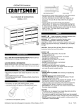
HARDWARE
NOTE: Not all assembly instructions will relate to your model.
TOOLS REQUIRED:
SIDE HANDLE ATTACHMENT
3/8-in Wrench
1/2-in Wrench
Cross-tip Screwdriver
Items Needed:
#14 - 10 x 3/4 Cross-tip Screw (Qty: 4)
Cross-tip Screwdriver
Process:
• Attach the side handle using (4) #14 - 10 x 3/4 Cross-tip
screws.
• Hand tighten. Do not overtighten.
HARDWARE INCLUDED:
CABINET HARDWARE
#14 - 10 x 5/8-in Hex Screws
(Qty: 16)
#14 - 10 x 3/4 Cross-tip Screw
(Qty: 4)
CHEST HARDWARE
5/16 - 18 Ball Stud (Qty: 4)
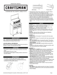
CASTER INSTALLATION
Items Needed:
#14 - 10 x 5/8-in Hex Screws (Qty: 16)
3/8-in Wrench
5/16 - 18 Clip-on Nut (Qty: 4)
Process:
NOTE: Use adequate personnel for this operation.
NOTE: Failure to install caster angles may result in
premature cabinet failure.
• Place the unit on its top. Use packaging material to
protect the paint finish.
• Position caster angles on the cabinet. Flanges should be
toward the inside and pointed up.
• Attach casters and caster angles using (4) #14 - 10 x 5/8
Hex Screws for each caster. Mount both swivel casters
on the same side of the cabinet as the side handle.
• Wrench tighten all screws. Do not overtighten.
• Return the unit to its upright position.
CARTON CONTENTS
Cabinet:
Literature
Caster pack
Handle pack
Chest:
Hardware Bag Assembly
Cover Label
Literature
Caster angles
(flanges inside)
2