1
Commodes
1.2 Symbols
Signal words are used in this manual and apply to hazards
or unsafe practices which could result in personal injury or
property damage. See the information below for definitions
of the signal words.
WARNING! Warning indicates a potentially hazardous
situation which, if not avoided, could result in death or
serious injury.
3 Setup
3.1 Installing/Removing the Seat Lid and Pail
Risk of Product Damage
– Before removing/installing seat and lid, allow the seat
and lid to reach room temperature if exposed to cold.
This will help prevent the seat clamps from breaking
when being removed or installed.
– DO NOT use excessive force when installing or
removing the seat and lid.
CAUTION! Caution indicates a potentially hazardous
situation which, if not avoided, may result in property
damage or minor injury or both.
Gives useful tips, recommendations and information for
efficient, trouble-free use.
Installing
IMPORTANT indicates a hazardous situation that could
result in damage to property if it is not avoided.
WARNING!
– When installing the seat onto the frame, make sure
that the seat is evenly spaced between the side frames
to ensure proper stability.
– When installing the seat and lid, install the seat first
and then the lid.
This product complies with Directive 93/42/EEC concerning
medical devices.
The launch date of this product is stated in the EC
declaration of conformity.
1.
1.3 Intended Use
The commode chair is to be used solely as an aid for going to the
toilet. Any other use is prohibited.
2.
3.
Temperature for use: 10–40° C (50–104° F)
4.
5.
6.
7.
Max. user weight: 160 kg (350 lb) (25 stone).
1.4 Service Life
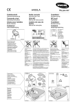
Align the grooves A on the underside of the seat B with the
commode frame C (Figure 2, page 1).
Push down firmly until the seat snaps into place.
Align the grooves D on the underside of the lid E with the seat
and the commode frame (Figure 3, page 1).
Push down firmly until the lid snaps in place.
Raise the seat and lid.
Put the pail F into place (Figure 4, page 1).
Lower the seat.
The expected service life of this product is five years when used in
accordance with the safety instructions, maintenance intervals and
correct use, stated in this manual. The effective service life can vary
according to frequency and intensity of use.
Removing
Maintenance should be done at least every six months.
1.
2.
3.
4.
2 Safety
2.1 Safety Information
WARNING!
– DO NOT use this product or any available optional
equipment without first completely reading and
understanding these instructions and any additional
instructional material such as user manuals, service
manuals or instruction sheets supplied with this
product or optional equipment. If you are unable to
understand the warnings, cautions or instructions,
contact a healthcare professional, dealer or technical
personnel before attempting to use this equipment otherwise, injury or damage may occur.
Risk of injury!
– DO NOT use if defective.
– DO NOT make any unauthorized alterations or
modifications to the product.
– Make sure that all attaching hardware, screws, nuts
and/or bolts are tight at all times.
– Protect the product against exposure to heat.
ACCESSORIES WARNING
– Invacare products are specifically designed and
manufactured for use in conjunction with Invacare
accessories. Accessories designed by other
manufacturers have not been tested by Invacare and
are not recommended for use with Invacare products.
2
When removing the seat or lid, remove the pail, lid and then
the seat.
5.
Raise the seat B and lid E
Remove the pail F (Figure 4, page 1).
Lower the seat and lid.
Grasp the back corner of the lid and lift up firmly (Figure 3, page
1).
Grasp the back corner of the seat and lift up firmly (Figure 2,
page 1).
3.2 Adjusting the Height of the Commode
WARNING!
– Ensure that the snap buttons fully protrude through the
same height adjustment hole of each leg extension. This
ensures that the leg extensions are securely locked in
position and that an even height adjustment is achieved.
1.
2.
3.
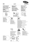
Depress the snap button F (Figure 5, page 1).
Slide the leg extension G up or down to the desired adjustment
hole (Figure 6, page 1).
Ensure the snap button protrudes fully through the adjustment
holes of the leg extension.
There will be an audible click when the snap button fully
engages.
4.
Repeat STEPS 1–3 for the remaining three legs.
Make sure that all four legs are adjusted to the same
height.
1180141A