1
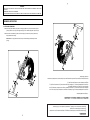
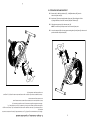
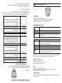
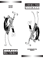
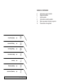
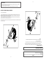
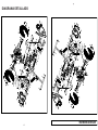
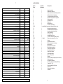
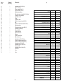
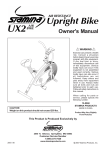
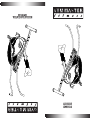
GM98510 CAUTION: Weight on this product should not exceed 250 lbs. AIR CYCLE OWNER’S MANUAL AIR BIKE GM98510 MODEL NO. 902-2 ASSEMBLY OPERATING INSTRUCTIONS REPLACEMENT PARTS ASSEMBLY OPERATING INSTRUCTIONS REPLACEMENT PARTS TOOLS REQUIRED FOR ASSEMBLY: PHILLIPS SCREWDRIVER ADJUSTABLE WRENCH TOOLS REQUIRED FOR ASSEMBLY: PHILLIPS SCREWDRIVER ADJUSTABLE WRENCH MODEL NO. 902-2 BICICLETA ESTATICA GM98510 AIR CYCLE OWNER’S MANUAL CAUTION: Weight on this product should not exceed 250 lbs. GM98510 GM98510 AIR CYCLE BICICLETA AERÓBICA – MANUAL DEL USUARIO OWNER’S MANUAL Product may vary slightly from picture. IMPORTANT: Read all instructions carefully before using this product. Return this owner’s manual for future reference. MODEL NO. 902-2 • Armado • Instrucciones ASSEMBLY de funcionamiento • Piezas de repuesto OPERATING INSTRUCTIONS REPLACEMENT PARTS requeridas CAUTION: Exercise of a strenuous nature, as is customarily done on this equipment, should not be undertaken without first consulting a physician. No specific health claims are made or implied as they relate to the equipment. Measurements made by the equipment are believed to be accurate, but only the measurements of your physician should be relied upon. CAUTION: Weight on this product should not exceed 250 lbs. Herramientas • Destornillador Phillips • Llave ajustable TOOLS REQUIRED FOR ASSEMBLY: PHILLIPS SCREWDRIVER ADJUSTABLE WRENCH Precaución: peso on quethis este equiposhould soporte debe exceder CAUTION: El Weight product notnoexceed 250 lbs. las 250 libras. TOOLS REQUIRED FOR ASSEMBLY: PHILLIPS SCREWDRIVER ADJUSTABLE WRENCH ASSEMBLY OPERATING INSTRUCTIONS REPLACEMENT PARTS Precaución: ejercicio excesivo, que podríaasllevarse a cabo en este no debe hacerse CAUTION: El Exercise of a strenuous nature, is customarily done onequipo, this equipment, should not sinbeprimero consultar con un médico. No se ahaphysician. tenido reclamos efectuados implícitos undertaken without first consulting No specific healtho claims arerelamade or cionados respecto este Las medidas que se made mencionan este equipo son lo to implied con as they relateato theequipo. equipment. Measurements by thepara equipment are believed más lo only posible, solamenteof lasyour medidas que should le otorgue un médico be exactas accurate,enbut the pero measurements physician be relied upon.serán las que deben seguirse. MODEL NO. 902-2 IMPORTANT: Read all instructions carefully before using this product. Return this owner’s Importante: todas las instrucciones detenidamente antes de utilizar este equipo. Guarde el manual forLea future reference. manual del usuario para cualquier consulta en el futuro. Product may vary slightly from picture. El equipo podría variar ligeramente con respecto a las imágenes. AIR CYCLE OWNER’S MANUAL GM98510 2 ■ Assembly instruction 6 ■ Exploded drawing 7 ■ Parts list 9 ■ Monitor instruction 10 ■ Training Pulse rate 11 ■ Training instruction 12 ■ Safety Precautions ÍNDICE DE CONTENIDOS 2 6 7 9 10 12 Instrucciones para el armado Diagrama detallado Lista de piezas Instrucciones sobre la pantalla Ritmo de pulsación durante el ejercicio Precauciones de seguridad Table of Contents GENERAL 2 GENERAL REMOVE ALL THE PARTS OF YOUR CYCLE FROM THE CARTON AND PLACE THEM ON THE FLOOR Retire todas las piezas de la bicicleta del empaque y colóquelas sobre el piso con cuidado. CAREFULLY. El armado de laCYCLE bicicleta es muy simple. ASSEMBLING YOUR IS SIMPLE. SigaTHESE estas instrucciones con cuidado y AND el armado le tomará a 20 minutos. FOLLOW INSTRUCTIONS CAREFULLY IT SHOULD TAKEunos YOU 15 AROUND 15-20 MINUTES. 2 ASSEMBLY INSTRUCTION INSTRUCCIONES PARA EL ARMADO 1.1.Acople los THE estabilizadores ATTACH STABILIZERS Attach the front stabilizer (45) with 2 leveling caps (44) to the front curve bracket of main • Acople elframe estabilizador delantero utilizando dos 2tapones niveladores (44) al brazo en curva (1) and secure, using 2(45) carriage bolts (46), curve washers (69) and 2 cap nuts (43). delantero del armazón principal (1) y asegure utilizando dos pernos de cabeza redonda (46), dos arandelas en curva (69)stabilizer y dos tuercas Attach the rear (2) withciegas 2 round(43). end caps (3) to the main frame (1) and secure, 4 Machine posterior screws (5).(2) utilizando dos tapas redondas (3) al armazón principal (1) y • Acople elusing estabilizador asegure utilizando cuatro tornillos para máquina (5). NOTE: Make sure you fasten the bolts securely to avoid shaking and discomfort when cycling. de ajustar los pernos firmemente para evitar vibraciones o incomodidad al momento Nota: Asegúrese de utilizar la bicicleta. NOTE: Make sure you fasten the bolts securely to avoid shaking and discomfort when cycling. Attach the front stabilizer (45) with 2 leveling caps (44) to the front curve bracket of main frame (1) and secure, using 2 carriage bolts (46), 2 curve washers (69) and 2 cap nuts (43). Attach the rear stabilizer (2) with 2 round end caps (3) to the main frame (1) and secure, using 4 Machine screws (5). 1. ATTACH THE STABILIZERS ASSEMBLY INSTRUCTION 2 REMOVE ALL THE PARTS OF YOUR CYCLE FROM THE CARTON AND PLACE THEM ON THE FLOOR CAREFULLY. ASSEMBLING YOUR CYCLE IS SIMPLE. FOLLOW THESE INSTRUCTIONS CAREFULLY AND IT SHOULD TAKE YOU AROUND 15-20 MINUTES. GENERAL 2 3 3 2. el asiento y SEAT el poste 2. Acople ATTACH THE SEAT AND POST del asiento • Retire 3 contratuercas nylonlocknuts M8 (17)(17), y las33x arandelas M8 (18) de from la parte las Remove the 3 x M8denylon M8 flat washers (18) theinferior lateral del asiento (21). under side of the seat (21). • Acople el asiento (21) al brazo triangular superior del poste del asiento (16) y alinee los tres agujeros del triangular asegurando con las 3 arandelas (18) (16) y lasand 3 contratuercas (17). brazo Attach seat (21) to top triangle bracket of seat post align the 3 holes • Deslice of la cubierta del postesecure del asiento sobre el poste asiento (17). (16). triangle bracket, with 3(4) washers (18) anddel 3 locknuts Nota:La pequeña ranura decover la cubierta del asiento Slide the seat post (4) to del the poste seat post (16). debe quedar en el extremo delThe poste delslot asiento. NOTE: small of seat post cover must be at end of seat post. • Inserte poste delseat asiento soporte del postetube del armazón principal asegúrelo el Insert the post (6) (16)altotubo the de seat post mounting of main frame (1) (1) andy secure in con la perilla del poste del asiento (29). position with the seat post knob (29). Remove the 3 x M8 nylon locknuts (17), 3 x M8 flat washers (18) from the under side of the seat (21). Attach seat (21) to top triangle bracket of seat post (16) and align the 3 holes of triangle bracket, secure with 3 washers (18) and 3 locknuts (17). Slide the seat post cover (4) to the seat post (16). NOTE: The small slot of seat post cover must be at end of seat post. Insert the seat post (16) to the seat post mounting tube of main frame (1) and secure in position with the seat post knob (29). 3 2. ATTACH THE SEAT AND SEAT POST 3 3. Acople los mangos 3. ATTACH THE HANDLEBARS • Presione la perilla pivote del mango (52) a través del tubo de soporte de armazón principal (1). Push the handlebar through the de support tube of the main frame • Acople el mango izquierdopivot (25 rod L) al(52) lado izquierdo los extremos expuestos de la(1). varilla pivote del mango (52). Lleve a cabo el mismo procedimiento con el mango derecho (25R). elAttach left handlebar assembly to the (63) left side exposed (27) endsyofuna thecontratuerca handlebar (17). • Fije mangothe izquierdo con una(25L) arandela de ajuste unaof arandela 4 4 pivot rod (52). Do the same procedure for right side handlebar (25R) assembly. Nota: Ajuste la arandela (27) y la contratuerca (17) un poco. No ajuste demasiado. After both side handlebar are fixed in position, please tighten the washers (27) and lock nut (17) well. Note: These should be tightened fully to ensure that the Fix in position with one adjust washer (63),one washer (27) and one lock nut (17) for left side handlebar. Tighten thecon washer (27), lock nut (17) a little bit. Don’t tighten it too much. • Lleve a cabo el mismoNote: procedimiento el mango derecho (25R). Do the same procedure for right side handlebar (25R) assembly. • Después de haber colocado y fijado ambos mangos, proceda a ajustar las arandelas (27) y las contratuercas (17) completamente. Nota: Ajuste totalmente para asegurarse de que los extremos de la varilla pivote (52) atraviesen la ends of the pivot rod (52) pass through the nylon insert in the locknut (17). inserción de nylon de la contratuerca (17). Do the same procedure to connect right handlebar (25R). Fit the 2 plastic caps (26) over the locknuts when they are fully tightened well. • Coloque las dos tapas de plástico (26) encima de las contratuercas una vez que queden bien ajustadas. Moisten the inside of the foam grips (22) with a little water or houseold furniture • Humedezca la parte de las de espuma (22) con un poco de agua poco o un polish and slideinterior onto both endsagarraderas of the handlebar (25R/25L). pulidor de muebles de uso casero y deslícelos sobre ambos extremos de los mangos (25R / 25L). • Acople el mango inferior (24) usando barra de (10) al mango superior Ajuste Attach lower handlebar (24) withlalinkage barunión (10) to upper handlebar (25L)(25L). tighten with 2utilizando dos pernos y dos arandelas bolts (68),2(68) curve washers (67) . en curva (67). • Lleve a cabo el mismo procedimiento para conectar el mango derecho (25 R). Aviso importante: Cuando ya se esté listo para pedalear la bicicleta, gire la perilla de control de tensión IMPORTANT (54) varias veces en el sentido contrario a las agujas del reloj para disminuir la resistencia de NOTICE: pedaleo.When Durante la the perilla deplease control de tension tensióncontrol en el sentido de several las agujas delwith reloj you el arepedaleo, ready togire pedal bike, turn knob (54) circle según locounter-clockwise desee para incrementar la resistencia de pedaleo. to decrease pedaling resistance. While pedaling, turn tension control knob several circle with clockwise per your request to increase pedaling resistance. IMPORTANT NOTICE: When you are ready to pedal the bike, please turn tension control knob (54) several circle with counter-clockwise to decrease pedaling resistance. While pedaling, turn tension control knob several circle with clockwise per your request to increase pedaling resistance. After both side handlebar are fixed in position, please tighten the washers (27) and lock nut (17) well. Note: These should be tightened fully to ensure that the ends of the pivot rod (52) pass through the nylon insert in the locknut (17). Fit the 2 plastic caps (26) over the locknuts when they are fully tightened well. Moisten the inside of the foam grips (22) with a little water or houseold furniture polish and slide onto both ends of the handlebar (25R/25L). Attach lower handlebar (24) with linkage bar (10) to upper handlebar (25L) tighten with 2 bolts (68),2 curve washers (67) . Do the same procedure to connect right handlebar (25R). Push the handlebar pivot rod (52) through the support tube of the main frame (1). Attach the left handlebar (25L) assembly to the left side of exposed ends of the handlebar pivot rod (52). Do the same procedure for right side handlebar (25R) assembly. Fix in position with one adjust washer (63),one washer (27) and one lock nut (17) for left side handlebar. Note: Tighten the washer (27), lock nut (17) a little bit. Don’t tighten it too much. Do the same procedure for right side handlebar (25R) assembly. 4 3. ATTACH THE HANDLEBARS 4 5 ATTACH THE PEDALS (HANDLEBAR DUAL ACTION MOVEMENT) 4.4. Acople los pedales (movimiento de acción dual del mango) NOTE: The right pedal (12R) has R marked on the bottom side of the pedal. The left pedal (12L) 5 Nota: El pedal derecho (12R) viene marcado con la letra R en la parte inferior. El pedal izquierdo (12) has L marked on the bottom side of the pedal. Both pedals (12L/R) have right hand threads. viene marcado con la letra L en la parte inferior. Ambos pedales (12L/R) tienen rosca hacia el lado Tighten both pedals (12L/R) by turning clockwise. derecho. Ajuste ambos pedales (12L/R) girando en el sentido de las agujas del reloj. Slide the two pedals washers (11) onto both pedal shafts of pedals (12L/R) • Deslice las arandelas de los dos pedales (11) sobre ambos ejes de los pedales (12L/R). • Inserte pedales los ejes (12L/R) a través de las unión (10). los Insert pedalde shafts of pedals (12L/R) through thebarras linkagedebars (10). • Deslice los espaciadores (9) sobre los ejes de los pedales. Slide spacers (9) onto pedal shafts. Warning: spacers (9) must be between linkage bar (10) Advertencia: espaciadores (9) deben quedar entre la barra de unión (10) ybar el cigüeñal andLos crank (50) so that there will be enough clearance between linkage (10) and (50) dejando el suficiente espacio entre la barra de unión y el cigüeñal. crank (50). • Enrosque los ejes de shafts los pedales (12L/R) al cigüeñal proceda a ajustar. Thread pedal of pedals (12L/R) into crank(50) (50)y and tighten. • Sujete los ejes de los pedales y enrosque la contratuerca 1/2” (8) a los ejes. • Ajuste ejespedal y la contratuerca 1/2” locknut (8) hasta que(8)laonto contratuerca quede ajustada contra el cigüeñal los Hold shafts and thread 1/2” pedal shafts. (50). Tighten pedal shafts and locknut 1/2” (8) until locknut 1/2” (8) are tight against crank (50). 5. Acople la pantalla 5. ATTACH THE MONITOR • Acople el conector del cable sensor a la entrada del cable de la pantalla que viene de la pantalla (31) sensor Attach(38) the plug of sensor to socket of monitor al cable que viene del wire armazón principal (1). wire which comes from monitor (31) to sensor wire which comes fron main frame (1).principal (1) utilizando dos tornillos (64). • Conectethe la pantalla (31)(38) utilizando el brazo (30) al armazón Connect monitor (31) with monitor bracket (30) to the main frame (1) using 2 AJUSTAVERIFIQUE QUE the TODOS LOS PERNOS Y TUERCAS HAYAN QUEDADO TOTALMENTE screws (64). DOS PARA SU SEGURIDAD Y COMODIDAD. RECHECK THAT ALL THE BOLTS AND NUTS ARE TIGHTENED SECURELY FOR YOUR SAFETY AND COMFORT. RECHECK THAT ALL THE BOLTS AND NUTS ARE TIGHTENED SECURELY FOR YOUR SAFETY AND COMFORT. Attach the plug of sensor wire to socket of monitor wire which comes from monitor (31) to the sensor wire (38) which comes fron main frame (1). Connect the monitor (31) with monitor bracket (30) to the main frame (1) using 2 screws (64). 5. ATTACH THE MONITOR Slide the two pedals washers (11) onto both pedal shafts of pedals (12L/R) Insert pedal shafts of pedals (12L/R) through the linkage bars (10). Slide spacers (9) onto pedal shafts. Warning: spacers (9) must be between linkage bar (10) and crank (50) so that there will be enough clearance between linkage bar (10) and crank (50). Thread pedal shafts of pedals (12L/R) into crank (50) and tighten. Hold pedal shafts and thread locknut 1/2” (8) onto pedal shafts. Tighten pedal shafts and locknut 1/2” (8) until locknut 1/2” (8) are tight against crank (50). NOTE: The right pedal (12R) has R marked on the bottom side of the pedal. The left pedal (12L) has L marked on the bottom side of the pedal. Both pedals (12L/R) have right hand threads. Tighten both pedals (12L/R) by turning clockwise. 5 4. ATTACH THE PEDALS (HANDLEBAR DUAL ACTION MOVEMENT) 5 EXPLODED DRAWING DIAGRAMA DETALLADO 6 6 6 EXPLODED DRAWING 6 7 7 1 1 Main Frame 2 1 Rear Stabilizer 3 2 Rear Stabilizer Round End Cap 4 1 Seat Post Cover 5 4 M5x12mm Machine Screw 6 2 Crank Bearing Retainer 7 4 Split Bearing 8 2 Locknut 1/2’ 9 2 Spacer 10 2 Linkage Bar 11 2 13mmx28mm Washer 12R/L 1p Pedal (with right thread) (R&L) 13 1 Seat Post Sleeve 14 2 Small Keyed Washer 15 1 Large Keyed Washer 16 1 Seat Post 17 7 M8 Locknut 18 3 8mmx12mm Washer 19 4 Round Head Screw (M4x15) 20R/L 1p Chain Guard (R&L) 21 1 Seat 22 2 Foam Grip 23 2 Handlebar End Cap 24 2 Lower Handbar 25L 1 Left Upper Handlebar 25R 1 Right Upper Handlebar 26 2 Pivot Rod Cap 27 2 8mmx23mm Washer 28 6 Plastic bushing 29 1 Locking Knob 30 1 Monitor bracket 31 1 Monitor 32 2 Bolt, Hex Head (M8 x 1.25 x 45mm) 33 2 Linkage Bushing 34 2 Fan Cage 35 4 Screw, Round Head (M5 x 75mm) 36 5 Nut (3/8" - 26) LISTA DE PIEZAS No. de Pieza 1 2 3 4 5 6 7 8 9 10 11 12R/L 13 14 15 16 17 18 19 20R/L 21 22 23 24 25L 25R 26 27 28 29 30 31 32 33 34 35 36 37 38 39 40 Cantidad (Unidades) Descripción 1 Armazón principal 1 Estabilizador posterior 2 Tapas redonda del estabilizador posterior 1 Cubierta del poste del asiento 4 Tornillo para máquina M5x12mm 2 Retenedor del cojinete del cigüeñal 4 Cojinete partido 2 Contratuerca 1/2” 2 Espaciador 2 Barra de unión 2 Arandela 13mmx28mm 1 unidadPedal (con rosca a la derecha) (Der. e Izq.) 1 Manga del poste del asiento 2 Arandela aseguradora pequeña 1 Arandela aseguradora grande 1 Poste del asiento 7 Contratuerca M8 3 Arandela 8mmx12mm 4 Tornillo de cabeza redonda (M4x15) 1 Unidad Protector de cadena (Der. e Izq.) 1 Asiento 2 Agarradera de espuma 2 Tapón del extremo del mango 2 Mango inferior 1 Mango superior izquierdo 1 Mango superior derecho 2 Tapas de la varilla pivote 2 Arandela 8mmx23mm 6 Casquillo de plástico 1 Perilla aseguradora 1 Brazo de la pantalla 1 Pantalla 2 Perno de cabeza hexagonal (M8x1.25x45mm) 2 Cojinete de unión 2 Carcasa del ventilador 4 Tornillo de cabeza redonda (M5x75mm) 5 Tuerca (3/8” – 26) 2 Perno roscado (M6x1x50mm) 1 Acelerador 2 Cojinete del ventilador 1 Ventilador PARTS NO. Q’TY (PCS) DESCRIPTION PARTS LIST 7 Fan Bushing 1 Fan 41 3 Plat washer (φ21xφ10.5x1.0t) 42 1 Fan Axle 43 2 Acorn Nut (M8 x 1.25) 44 2 Leveling Cap (28.6mm) 45 1 Front Stabilizer 46 2 Carriage Bolt (M8 x 1.25 x 38mm) 47 1 Chain (1/4" pitch) 48 1 Wavy Washer 49 1 Roll Pin 50 1 Crank and Sprocket 51 11 Screw, Round Head (M5 x 25) 52 1 Axle 53 1 Screw, Flat Head (M5 x 0.8 x 15mm) 54 1 Tension Knob 55 4 Nylock cap (M6x1.0) 56 1 Wavy Washer (M10) 57 2 Nut (M6x1.0) 58 1 Tension Belt 59 1 Tension Spring 60 1 Hook 61 4 Screw (M6 x 1 x 25mm) 62 2 Resistance Hub 63 2 Plat washer (φ25xφ16.3x0.5t) 64 6 Screw, Round Head (M5 x 15) 65 4 Screw, Round Head (M5 x 12) 66 2 Plat washer (φ22xφ8.4x1.5t) 67 4 Curve washer (φ13xφ6.2x1.5t) 68 4 Screw (M6x12) 69 4 Curve washer (φ18xφ8.2x1.5t) 70 1 Allen wrench 71 1 Wrench 72 1 Wrench Descripción 2 40 Cantidad (Unidades) 39 No. de Pieza Speed Pickup Arandela plana (21x10.5x1.0t) Eje del ventilador Tuerca roscada (M8x1.25) Tapón nivelador (28.6mm) Estabilizador delantero Perno de cabeza redonda (M8x1.25x38mm) Cadena (1/4” de intensidad) Arandela en onda Clavija Cigüeñal y rueda Tornillo de cabeza redonda (M5x25) Eje Tornillo de cabeza plana (M5x0.8x15mm) Perilla de tensión Tapa aseguradora de nylon (M6x1.0) Arandela en onda (M10) Tuerca (M6x1.0) Correa de tensión Resorte de tensión Gancho Tornillo (M6x1x25mm) Eje de resistencia Arandela plana (25x16.3x0.5t) Tornillo de cabeza redonda (M5x15) Tornillo de cabeza redonda (M5x12) Arandela plana (22x8.4x1.5t) Arandela em curva (13x6.2x1.5t) Tornillo (M6x12) Arandela em curva (18x8.2x1.5t) Llave Allen Llave Llave Eye Bolt (M6 x 1 x 50mm) 1 3 1 2 2 1 2 1 1 1 1 11 1 1 1 4 1 2 1 1 1 4 2 2 6 4 2 4 4 4 1 1 1 2 38 Q’TY (PCS) 41 42 43 44 45 46 47 48 49 50 51 52 53 54 55 56 57 58 59 60 61 62 63 64 65 66 67 68 69 70 71 72 8 8 37 PARTS NO. DESCRIPTION 8 9 If the display becomes illegible or only partial segments appear, please remove the batteries, wait 20 seconds and refit. 9 TROUBLE SHOOTING Do not mix a new battery with an old battery. Use the same type of battery. Do not mix an alkaline battery with another type of battery. Rechargeable batteries are not recommended. Note: Dismount the meter from the bike. Open the battery door on the back of the meter. The meter operates with 2pcs AA batteries. Batteries Installation: NOTE: The meter will shut off automatically after four minutes of inactivity. All function values will be kept. Push the MODE button and hold it down for three seconds to reset all functions to zero. FUNCTIONS SCAN DESCRIPTION TIME SPEED DISTANCE CALORIES ● Automatically scans each function to time, speed, distance, calories, and heart rate in sequence with change every four seconds. Press and release the MODE button until SCAN appears on the display. Display the time for one second up to 99:59 minutes. ● Display the current speed from zero to 999.9 KM per hour. ● Display the distance from zero to 99.99 KM. ● ● Display the calories consumption from zero to 999.9 kcal. The calories readout is an estimate for an average user. It should be used only as a comparison between workouts on this unit. ● ● USING THE METER POWER ON POWER OFF MODE BUTTON ● Pedal movement or push the MODE button. ● ● Automatic shut off after four minutes of inactivity. Press to select display functions, include SCAN, TIME, SPEED, DISTANCE and CALORIES. Press and hold for three seconds to reset all functions to zero. DESCRIPTION Operational Instructions Simply start pedaling and way you go! The value of time, distance and calories will start counting upwards. Adjust the resistance level with the large dial control knob. Quick start MONITOR INSTRUCTION INSTRUCCIONES SOBRE LA PANTALLA INSTRUCCIONES SOBRE LA PANTALLA (figura) Inicio rápido • Simplemente comience a pedalear y se iniciará el sistema. Inicio rápido • El valor de tiempo, distancia y calorías comenzará a aumentar en el Quick startcontador. • Simplemente comience pedalear se iniciará utilizando el sistema.la perilla de control. • Regulea el nivel deyresistencia Simply start pedaling and way you comenzará go! • El valor de tiempo, distancia y calorías a aumentar en el contador. The of time, distance and calories will start counting upwards. • Regule el value nivel de resistencia utilizando la perilla de control. AdjustInstrucciones the resistance level with the large dial control knob. de funcionamiento Cómo utilizar el Descripción contadorInstructions Operational Encendido • Moviendo el pedal o presionando el botón MODE. USING THE DESCRIPTION • Apagado automático después de cuatro minutos METER Apagado de inactividad. ● Pedal movement or push the MODE button. POWER ON POWERBotón OFF MODE● MODE BUTTON ● ● Automatic• shut off afterpara four minutes inactivity. Presione mostraroflas funciones. Éstas Press to selectincluyen display functions, include SCAN, TIME, SPEED, DISTANCE SCAN (escaneo), TIME (tiempo), SPEED and CALORIES. (velocidad), DISTANCE (distancia) y CALORIES (calorías). Press and hold for three seconds to reset all functions to zero. • Presione y mantenga presionado durante tres segundos para revertir todas las funciones a cero. FUNCTIONS DESCRIPTION SCAN Funciones ● SCAN TIME SPEED DISTANCE ● ● ● Automatically scans each function to time, speed, distance, calories, and heart Descripción rate in sequence with change every four seconds. andde release the MODE • Automáticamente escanea cadaPress función button until SCAN appears on the display. tiempo, velocidad, distancia, calorías y ritmo Display the time for oneen second up to 99:59 minutes.cada cuatro cardiaco secuencia cambiando segundos. y suelte el botón MODE hasta Display the current speed Presione from zero to 999.9 KM per hour. que la palabra SCAN aparezca en la pantalla. Display the distance from zero to 99.99 KM. ● Display the consumption zeroun to segundo 999.9 kcal.hasta 99: 59 CALORIES TIME • calories Muestra el tiempofrom desde ● The calories readout is an estimate for an average user. It should be used only minutos. as a comparison between workouts on this unit. SPEED • Muestra la velocidad actual desde cero hasta NOTE: The meter will shut off automatically999.9 after four of inactivity. All function values will be kept. KMminutes por hora. Push the MODE button and hold it down for three seconds to reset all functions to zero. DISTANCE • Muestra la distancia desde cero hasta 99.99 KM. Batteries Installation: CALORIES • Muestra el consumo de calorías desde cero hasta Dismount the meter from the bike. 999.9 kcal. Open the battery door on the back of•theLa meter. lectura de las calorías es un estimado para el The meter operates with 2pcs AA batteries. usuario promedio. Debe usarse solo como comparativo entre rutinas que se hagan en este equipo. Note: Do not mix a new battery with an old battery. Use the same type of battery. Do not mix an alkaline battery with another type of battery. Rechargeable batteries are not recommended. después de cuatro minutos de inactividad. Los Nota: El contador Nota:se Elapagará contadorautomáticamente se apagará automáticamente después de cuatro minutos de valores de todas las funciones se conservarán. el se botón MODE y manténgalo inactividad. Los valores de todas lasPresione funciones conservarán. Presione el presionado TROUBLE SHOOTING durante tres segundos para revertir todaspresionado las funciones a cero. botón MODE y manténgalo durante tres segundos para revertir todas las funciones If the display becomes illegible aorcero. only partial segments appear, please remove the batteries, wait Instalación lasrefit. baterías: 20 secondsdeand 9 MONITOR INSTRUCTION Instalación las baterías: • Retire el contador de la de bicicleta. • Abra la tapa del compartimento de baterías en la parte posterior del contador. • Retire el contador de latipo bicicleta. • El contador funciona como dos baterías AA. • Abra la tapa del compartimento de 9 baterías en la parte posterior del contador. El contador funciona como dos baterías tipo AA. • Nota: • No combine baterías nuevas con usadas. • Utilice el mismo tipo de baterías. No combine baterías alcalinas con otros tipos de baterías. • No se recomienda utilizar baterías recargables. 10 10 Solución de problemas Si la pantalla no fuera legible o sólo aparecieran segmentos parciales, retire las baterías, espere unos 20Training segundos yPulse vuelva aRate colocarlas. Ritmo de pulsación durante el ejercicio Pulso Edad Training Pulse Rate 10 11 11 Highest pulse rate = 168 x 0.7 = 117 pulse/min You are 52 years of age and would like to start exercising. Maximum pulse rate = 220 - 52(age) = 168 pulse/min Minimum pulse rate = 168 x 0.6 = 101 pulse/min Example: The optimum training amount consists of three workouts per week 30 minutes each. The units will be continuously easier and you will feel a lot fitter during your normal day To reach an optimum at burning rate, it is advisable to keep the pulse rate between 60% – 70% of the maximum pulse rate. Even after a short period of regular exercises you will notice that you constantly have to increase the resistance to reach your optimum pulse rate. Success The body starts to burn fat at approx. 60% of the maximum pulse rate. Stretching is also helpful for the prevention of muscle aches. Fat burning While exercising the pulse rate should always be between 60% - 85% of the maximum pulse rate. For your personal training rates please see the attached pulse rate chart on page 9. The time-length of your training session can be calculated with the following rule of thumb: When starting to exercise you should keep your rate at 60% of your maximum pulse rate in the first couple of weeks. With increasing improvement of fitness the pulse rate should be slowly increased to 85% of your maximum pulse rate. To introduce an effective cool-down of the muscles and the metabolism the intensity should be drastically decreased during the last 5 – 10 minutes. Cool down: Daily training session: approx. 10 min. per unit 2-3 x per week: approx. 30 min. per unit 1-2 x per week: approx. 60 min. per unit During the actual training a rate of 70% -85% of the maximum pulse rate should be chosen. Maximum pulse rate = 220 - Age Training session: As a rule of thumb the following formula is commonly used: Here you can do some stretching and training with low resistance. The heart rate is used as guideline. Before every training you should warm-up for 5-10 minutes. To achieve maximum results the right intensity has to be chosen. Warm-up: Intensity Training Organisation If you have not been physically active for a longer period of time and also to avoid health risks you should consult your general physician before starting to exercise. This can be done by increasing the resistance, a higher frequency or longer training periods. With increasing improvement of fitness the training intensity should be increased to 70% 85% of your maximum pulse rate. To achieve a considerable improvement of your physical resistance and your health, some aspects of how to find the most efficient amount of training should be followed: During the first weeks it is advisable to start with a pulse rate of 101, afterwards increase it to 117. TRAINING INSTRUCTION INSTRUCCIONES SOBRE LOS EJERCICIOS Para lograr una mejora sustancial de su resistencia física y de su salud, debe prestarse atención a algunos aspectos que permitan alcanzar la cantidad de ejercicios eficiente. Si no se ha estado físicamente activo durante un periodo prolongado, y para evitar riesgos a su salud, debe consultarse con un médico antes de iniciar un programa de ejercicios. Intensidad Con el fin de lograr óptimos resultados, debe seleccionarse la intensidad apropiada. Utilice el ritmo cardiaco como pauta. Como regla general, comúnmente se utiliza la siguiente fórmula: Ritmo de pulsación máximo = 220 – Edad Durante el ejercicio, el ritmo de pulsación siempre debe encontrarse entre 60% y 85% del ritmo de pulsación máximo. Para sus ritmos de ejercicios personales, véase el cuadro adjunto con los ritmos de pulsaciones en la página 9. En un comienzo, debe mantenerse el ritmo a 60% del ritmo de pulsación máximo durante el primer par de semanas. Conforme se mejora la condición física, el ritmo de pulsación debe incrementarse lentamente hasta un 85% del ritmo de pulsación máximo. Quemado de grasa El cuerpo comienza a quemar grasa en aproximadamente 60% del ritmo pulsación máximo. Para alcanzar un ritmo de quemado de grasa óptimo, se recomienda mantener el ritmo de pulsación entre 60% y 70% del ritmo de pulsación máximo. La cantidad de ejercicios óptima consiste de tres rutinas de ejercicios por semana de 30 minutos cada una. Durante las primeras semanas, se recomienda comenzar con un ritmo de pulsación de 101. Luego se puede incrementar a 117. Conforme se mejora la condición física, la intensidad de los ejercicios debe incrementarse lentamente hasta un 70% a 85% del ritmo de pulsación máximo. Esto puede llevarse a cabo incrementando la resistencia, aumentando la frecuencia o la duración de los periodos de ejercicios. Organización del programa de ejercicios Calentamiento: Antes de iniciar su programa de ejercicios, debe llevarse a cabo un calentamiento de entre 5 a 10 minutos. Para el calentamiento, se puede llevar a cabo algunos ejercicios de estiramiento o ejercicios de resistencia mínima. Sesión de ejercicios: Durante la sesión de ejercicios, debe mantenerse un ritmo de 70% a 85% del ritmo de pulsación máximo. La duración de la sesión de ejercicios puede calcularse utilizando la siguiente regla general: • Sesión de ejercicios diaria: Aproximadamente 10 minutos por unidad. • 2 a 3 veces por semana: Aproximadamente 30 minutos por unidad. • 1 a 2 veces por semana: Aproximadamente 60 minutos por unidad. Enfriamiento: Para poder enfriar de manera efectiva los músculos y el metabolismo, la intensidad debe disminuirse drásticamente durante los últimos 5 a 10 minutos. Los ejercicios de estiramiento también son muy útiles para prevenir dolores musculares. Las unidades le resultarán progresivamente más fáciles y se sentirá físicamente mejor Ritmo de pulsación más alto = 168 x 0.7 = 117 pulsación/minuto Éxito del programa Aún después de un periodo corto de llevar a cabo los ejercicios de manera regular, se notará que es necesario incrementar constantemente la resistencia para alcanzar un ritmo de pulsación óptimo. Ejemplo: Si se tiene 52 años de edad y se desea iniciar un programa de ejercicios: Ritmo de pulsación máximo = 220 – 52 (edad) = 168 pulsación/minuto Ritmo de pulsación mínimo = 168 x 0.6 = 101 pulsación/minuto 11 durante el día. 12 Gracias por haber adquirido nuestro producto. Aún cuando hemos hecho nuestros mayores esfuerzos para asegurarnos de que la calidad de cada uno de nuestros productos sea la mejor, podrían ocurrir algunos errores y/o omisiones. En el caso de que encontrara que este producto tuviera alguna pieza defectuosa o faltante, póngase en contacto con nosotros para su inmediata sustitución. 12 PRECAUCIONES DE SEGURIDAD Este producto ha sido diseñado sólo para uso doméstico. Cualquier responsabilidad y las condiciones de garantía no serán aplicables a aquellos productos que hayan sido sujetos a usos profesionales o productos que hayan sido utilizados en un gimnasio comercial. Read all instruction before assembly and operation. 8. Before using this equipment to exercise, always do stretching exercises to properly warm up. 9. Use this equipment only for its intended use as described in this manual. 10. Always wear appropriate workout clothing and shoes when exercising, do not wear robs or other clothing Este equipo de ejercicios ha sido diseñado y construido para ofrecerle una máxima seguridad. Sin embargo, debe prestarse atención a ciertas precauciones al momento de utilizar cualquier equipo de ejercicios. Asegúrese de leer todo el manual antes de armar y utilizar este equipo. Además, preste atención a las siguientes precauciones de seguridad: Do not insert any object into any openings 7. If dizziness, nausea, chest pains, or any other abnormal symptoms are experienced while using this 1. Mantenga el equipo lejos del alcance de los niños y mascotas en todo momento. 2. Sólo una persona a la vez debe utilizar este equipo. 3. Si sintiera mareo, náuseas, dolores en el pecho o cualquier otro síntoma anormal durante la utilización de este equipo, DETENGA el ejercicio inmediatamente. CONSULTE CON UN MÉDICO INMEDIATAMENTE. 4. Utilice este equipo sobre una superficie libre y nivelada. No lo utilice en exteriores ni cerca al agua. 5. Mantenga las manos y pies lejos de las partes en movimiento. 6. No inserte ningún tipo de objeto dentro de las aberturas. 7. Lea todas las instrucciones antes de armar y utilizar el equipo. 8. Antes de utilizar este equipo para llevar a cabo sus ejercicios, efectúe algunos ejercicios de estiramiento a manera de calentamiento. 9. Utilice este equipo sólo para los fines que se describen en este manual. 10. Utilice la vestimenta y calzado de ejercicios apropiados para hacer sus ejercicios. No utilice batas u otras prendas que podrían enredarse o atascarse en el equipo. 6. 3. Advertencia: Antes de iniciar cualquier programa de ejercicios, consulte con su médico. Esto es especialmente importante para aquellas personas mayores de 35 años o personas con problemas de salud preexistentes. Lea todas las instrucciones antes de utilizar cualquier equipo de ejercicios. No asumimos ningún tipo de responsabilidad debido a lesiones personales o daños a la propiedad ocasionados por el uso de este producto, Keep hands and feet away from any moving parts. Only one person at a time should use this equipment. Advertencia: Podrían producirse lesiones en niños pequeños si se utiliza la bicicleta de ejercicios en su presencia sin haber colocado los protectores apropiados. Always use this equipment on a clear and level surface. Do not use outdoors or near water. 5. Keep children and pets away from this equipment at all times. 2. Advertencia: Coloque la bicicleta sobre una superficie nivelada para utilizarla. WARNING THIS BIKE SHOULD ALWAYS BE PLACED ON A LEVELSURFACE FOR USE. WARNING INJURIES TO YOUNG CHILDREN ARE LIKELY TO OCCUR IF THE EXERCISE BIKE IS OPERATED IN THEIR VICINITY WITHOUT PROPERLY FITTED GUARDS. WARNING: BEFORE BEGINNING ANY EXERCISE PROGRAM CONSULT YOUR PHYSICIAN. THIS IS ESPECIALLY IMPORTANT FOR INDIVIDUALS OVER THE AGE OF 35 OR PERSON WITH PRE-EXISTING HEALTH PROBLEMS. READ ALL INSTRUCTIONS BEFORE USING ANY FITNESS QUIPMENT. WE ASSUME NO RESPONSILITY FOR PEROSNAL INJURY OR PROPERTY DAMAGE SUSTAINS BY OR THROUGH THE USE OF THIS PRODUCT. that could become caught in the equipment. 4. equipment, STOP the workout at once. CONSULT A PHYSICIAN IMMEDIATELY. 1. This exercise equipment was designed and built for optimum safety. However, certain precautions apply whenever you operate a piece of exercise equipment. Be sure to read the entire manual before assembly and operation of this machine. Also, please note the following safety precautions: This products has been designed for home use only. Product liability and guarantee conditions will not be applicable to products being subjected to professional use or products being used in a gym center. Thank you for purchasing our product. Even though we go to great efforts to ensure the quality of each product we produce, occasional errors and /or omissions do occur. In any event should you find this product to has either a defective or a missing part please contact us for a replacement. SAFETY PRECAUTIONS 12 GM98510 CAUTION: Weight on this product should not exceed 250 lbs. AIR CYCLE OWNER’S MANUAL AIR BIKE GM98510 MODEL NO. 902-2 TOOLS REQUIRED FOR ASSEMBLY: PHILLIPS SCREWDRIVER ADJUSTABLE WRENCH ASSEMBLY OPERATING INSTRUCTIONS REPLACEMENT PARTS ASSEMBLY OPERATING INSTRUCTIONS REPLACEMENT PARTS TOOLS REQUIRED FOR ASSEMBLY: PHILLIPS SCREWDRIVER ADJUSTABLE WRENCH MODEL NO. 902-2 BICICLETA ESTATICA GM98510 AIR CYCLE OWNER’S MANUAL CAUTION: Weight on this product should not exceed 250 lbs. GM98510 GM98510 AIR CYCLE BICICLETA AERÓBICA – MANUAL DEL USUARIO OWNER’S MANUAL Product may vary slightly from picture. IMPORTANT: Read all instructions carefully before using this product. Return this owner’s manual for future reference. CAUTION: Weight on this product should not exceed 250 lbs. CAUTION: Exercise of a strenuous nature, as is customarily done on this equipment, should not be undertaken without first consulting a physician. No specific health claims are made or implied as they relate to the equipment. Measurements made by the equipment are believed to be accurate, but only the measurements of your physician should be relied upon. MODEL NO. 902-2 • Armado • Instrucciones ASSEMBLY de funcionamiento • Piezas de repuesto OPERATING INSTRUCTIONS REPLACEMENT PARTS requeridas Herramientas • Destornillador Phillips • Llave ajustable MODEL NO. 902-2 Product may vary slightly from picture. AIR CYCLE OWNER’S MANUAL GM98510 El equipo podría variar ligeramente con respecto a las imágenes. ASSEMBLY OPERATING INSTRUCTIONS REPLACEMENT PARTS IMPORTANT: Read all instructions carefully before using this product. Return this owner’s Importante: todas las instrucciones detenidamente antes de utilizar este equipo. Guarde el manual forLea future reference. manual del usuario para cualquier consulta en el futuro. Precaución: ejercicio excesivo, que podríaasllevarse a cabo en este no debe hacerse CAUTION: El Exercise of a strenuous nature, is customarily done onequipo, this equipment, should not sinbeprimero consultar con un médico. No se ahaphysician. tenido reclamos efectuados implícitos undertaken without first consulting No specific healtho claims arerelamade or cionados respecto este Las medidas que se made mencionan este equipo son lo to implied con as they relateato theequipo. equipment. Measurements by thepara equipment are believed más lo only posible, solamenteof lasyour medidas que should le otorgue un médico be exactas accurate,enbut the pero measurements physician be relied upon.serán las que deben seguirse. Precaución: peso on quethis este equiposhould soporte debe exceder CAUTION: El Weight product notnoexceed 250 lbs. las 250 libras. TOOLS REQUIRED FOR ASSEMBLY: PHILLIPS SCREWDRIVER ADJUSTABLE WRENCH TOOLS REQUIRED FOR ASSEMBLY: PHILLIPS SCREWDRIVER ADJUSTABLE WRENCH ÍNDICE DE CONTENIDOS 2 6 7 9 10 12 Instrucciones para el armado Diagrama detallado Lista de piezas Instrucciones sobre la pantalla Ritmo de pulsación durante el ejercicio Precauciones de seguridad ■ 12 ■ 11 ■ 10 ■ 9 ■ 7 ■ 6 ■ 2 Table of Contents Safety Precautions Training instruction Training Pulse rate Monitor instruction Parts list Exploded drawing Assembly instruction 2 GENERAL GENERAL REMOVE ALL THE PARTS OF YOUR CYCLE FROM THE CARTON AND PLACE THEM ON THE FLOOR Retire todas las piezas de la bicicleta del empaque y colóquelas sobre el piso con cuidado. CAREFULLY. El armado de laCYCLE bicicleta es muy simple. ASSEMBLING YOUR IS SIMPLE. SigaTHESE estas instrucciones con cuidado y AND el armado le tomará a 20 minutos. FOLLOW INSTRUCTIONS CAREFULLY IT SHOULD TAKEunos YOU 15 AROUND 15-20 MINUTES. 2 ASSEMBLY INSTRUCTION INSTRUCCIONES PARA EL ARMADO 1.1.Acople los THE estabilizadores ATTACH STABILIZERS Attach the front stabilizer (45) with 2 leveling caps (44) to the front curve bracket of main • Acople elframe estabilizador delantero utilizando dos 2tapones niveladores (44) al brazo en curva (1) and secure, using 2(45) carriage bolts (46), curve washers (69) and 2 cap nuts (43). delantero del armazón principal (1) y asegure utilizando dos pernos de cabeza redonda (46), dos arandelas en curva (69)stabilizer y dos tuercas Attach the rear (2) withciegas 2 round(43). end caps (3) to the main frame (1) and secure, 4 Machine posterior screws (5).(2) utilizando dos tapas redondas (3) al armazón principal (1) y • Acople elusing estabilizador asegure utilizando cuatro tornillos para máquina (5). NOTE: Make sure you fasten the bolts securely to avoid shaking and discomfort when cycling. de ajustar los pernos firmemente para evitar vibraciones o incomodidad al momento Nota: Asegúrese de utilizar la bicicleta. NOTE: Make sure you fasten the bolts securely to avoid shaking and discomfort when cycling. Attach the rear stabilizer (2) with 2 round end caps (3) to the main frame (1) and secure, using 4 Machine screws (5). Attach the front stabilizer (45) with 2 leveling caps (44) to the front curve bracket of main frame (1) and secure, using 2 carriage bolts (46), 2 curve washers (69) and 2 cap nuts (43). 1. ATTACH THE STABILIZERS ASSEMBLY INSTRUCTION 2 REMOVE ALL THE PARTS OF YOUR CYCLE FROM THE CARTON AND PLACE THEM ON THE FLOOR CAREFULLY. ASSEMBLING YOUR CYCLE IS SIMPLE. FOLLOW THESE INSTRUCTIONS CAREFULLY AND IT SHOULD TAKE YOU AROUND 15-20 MINUTES. GENERAL 2 3 2. el asiento y SEAT el poste 2. Acople ATTACH THE SEAT AND POST del asiento 3 • Retire 3 contratuercas nylonlocknuts M8 (17)(17), y las33x arandelas M8 (18) de from la parte las Remove the 3 x M8denylon M8 flat washers (18) theinferior lateral del asiento (21). under side of the seat (21). • Acople el asiento (21) al brazo triangular superior del poste del asiento (16) y alinee los tres agujeros del triangular asegurando con las 3 arandelas (18) (16) y lasand 3 contratuercas (17). brazo Attach seat (21) to top triangle bracket of seat post align the 3 holes • Deslice of la cubierta del postesecure del asiento sobre el poste asiento (17). (16). triangle bracket, with 3(4) washers (18) anddel 3 locknuts Nota:La pequeña ranura decover la cubierta del asiento Slide the seat post (4) to del the poste seat post (16). debe quedar en el extremo delThe poste delslot asiento. NOTE: small of seat post cover must be at end of seat post. • Inserte poste delseat asiento soporte del postetube del armazón principal asegúrelo el Insert the post (6) (16)altotubo the de seat post mounting of main frame (1) (1) andy secure in con la perilla del poste del asiento (29). position with the seat post knob (29). 3 Insert the seat post (16) to the seat post mounting tube of main frame (1) and secure in position with the seat post knob (29). Slide the seat post cover (4) to the seat post (16). NOTE: The small slot of seat post cover must be at end of seat post. Attach seat (21) to top triangle bracket of seat post (16) and align the 3 holes of triangle bracket, secure with 3 washers (18) and 3 locknuts (17). Remove the 3 x M8 nylon locknuts (17), 3 x M8 flat washers (18) from the under side of the seat (21). 2. ATTACH THE SEAT AND SEAT POST 3 3. Acople los mangos 4 • Presione la perilla pivote del mango (52) a través del tubo de soporte de armazón principal (1). Push the handlebar through the de support tube of the main frame • Acople el mango izquierdopivot (25 rod L) al(52) lado izquierdo los extremos expuestos de la(1). varilla pivote del mango (52). Lleve a cabo el mismo procedimiento con el mango derecho (25R). elAttach left handlebar assembly to the (63) left side exposed (27) endsyofuna thecontratuerca handlebar (17). • Fije mangothe izquierdo con una(25L) arandela de ajuste unaof arandela 4 3. ATTACH THE HANDLEBARS pivot rod (52). Do the same procedure for right side handlebar (25R) assembly. Nota: Ajuste la arandela (27) y la contratuerca (17) un poco. No ajuste demasiado. Fix in position with one adjust washer (63),one washer (27) and one lock nut (17) for left side handlebar. Tighten thecon washer (27), lock nut (17) a little bit. Don’t tighten it too much. • Lleve a cabo el mismoNote: procedimiento el mango derecho (25R). Do the same procedure for right side handlebar (25R) assembly. • Después de haber colocado y fijado ambos mangos, proceda a ajustar las arandelas (27) y las contratuercas (17) completamente. After both side handlebar are fixed in position, please tighten the washers (27) and lock nut (17) well. Note: These should be tightened fully to ensure that the Nota: Ajuste totalmente para asegurarse de que los extremos de la varilla pivote (52) atraviesen la ends of the pivot rod (52) pass through the nylon insert in the locknut (17). inserción de nylon de la contratuerca (17). Fit the 2 plastic caps (26) over the locknuts when they are fully tightened well. Do the same procedure to connect right handlebar (25R). • Coloque las dos tapas de plástico (26) encima de las contratuercas una vez que queden bien ajustadas. Moisten the inside of the foam grips (22) with a little water or houseold furniture • Humedezca la parte de las de espuma (22) con un poco de agua poco o un polish and slideinterior onto both endsagarraderas of the handlebar (25R/25L). pulidor de muebles de uso casero y deslícelos sobre ambos extremos de los mangos (25R / 25L). • Acople el mango inferior (24) usando barra de (10) al mango superior Ajuste Attach lower handlebar (24) withlalinkage barunión (10) to upper handlebar (25L)(25L). tighten with 2utilizando dos pernos y dos arandelas bolts (68),2(68) curve washers (67) . en curva (67). • Lleve a cabo el mismo procedimiento para conectar el mango derecho (25 R). Aviso importante: Cuando ya se esté listo para pedalear la bicicleta, gire la perilla de control de tensión IMPORTANT (54) varias veces en el sentido contrario a las agujas del reloj para disminuir la resistencia de NOTICE: pedaleo.When Durante la the perilla deplease control de tension tensióncontrol en el sentido de several las agujas delwith reloj you el arepedaleo, ready togire pedal bike, turn knob (54) circle según locounter-clockwise desee para incrementar la resistencia de pedaleo. to decrease pedaling resistance. While pedaling, turn tension control knob several circle with clockwise per your request to increase pedaling resistance. IMPORTANT NOTICE: When you are ready to pedal the bike, please turn tension control knob (54) several circle with counter-clockwise to decrease pedaling resistance. While pedaling, turn tension control knob several circle with clockwise per your request to increase pedaling resistance. Do the same procedure to connect right handlebar (25R). Attach lower handlebar (24) with linkage bar (10) to upper handlebar (25L) tighten with 2 bolts (68),2 curve washers (67) . Moisten the inside of the foam grips (22) with a little water or houseold furniture polish and slide onto both ends of the handlebar (25R/25L). Fit the 2 plastic caps (26) over the locknuts when they are fully tightened well. After both side handlebar are fixed in position, please tighten the washers (27) and lock nut (17) well. Note: These should be tightened fully to ensure that the ends of the pivot rod (52) pass through the nylon insert in the locknut (17). Fix in position with one adjust washer (63),one washer (27) and one lock nut (17) for left side handlebar. Note: Tighten the washer (27), lock nut (17) a little bit. Don’t tighten it too much. Do the same procedure for right side handlebar (25R) assembly. Attach the left handlebar (25L) assembly to the left side of exposed ends of the handlebar pivot rod (52). Do the same procedure for right side handlebar (25R) assembly. Push the handlebar pivot rod (52) through the support tube of the main frame (1). 3. ATTACH THE HANDLEBARS 4 4 ATTACH THE PEDALS (HANDLEBAR DUAL ACTION MOVEMENT) 4.4. Acople los pedales (movimiento de acción dual del mango) 5 NOTE: The right pedal (12R) has R marked on the bottom side of the pedal. The left pedal (12L) 5 Nota: El pedal derecho (12R) viene marcado con la letra R en la parte inferior. El pedal izquierdo (12) has L marked on the bottom side of the pedal. Both pedals (12L/R) have right hand threads. viene marcado con la letra L en la parte inferior. Ambos pedales (12L/R) tienen rosca hacia el lado Tighten both pedals (12L/R) by turning clockwise. derecho. Ajuste ambos pedales (12L/R) girando en el sentido de las agujas del reloj. Slide the two pedals washers (11) onto both pedal shafts of pedals (12L/R) Slide spacers (9) onto pedal shafts. Warning: spacers (9) must be between linkage bar (10) • Deslice las arandelas de los dos pedales (11) sobre ambos ejes de los pedales (12L/R). • Inserte pedales los ejes (12L/R) a través de las unión (10). los Insert pedalde shafts of pedals (12L/R) through thebarras linkagedebars (10). • Deslice los espaciadores (9) sobre los ejes de los pedales. Advertencia: espaciadores (9) deben quedar entre la barra de unión (10) ybar el cigüeñal andLos crank (50) so that there will be enough clearance between linkage (10) and (50) dejando el suficiente espacio entre la barra de unión y el cigüeñal. crank (50). • Enrosque los ejes de shafts los pedales (12L/R) al cigüeñal proceda a ajustar. Thread pedal of pedals (12L/R) into crank(50) (50)y and tighten. • Sujete los ejes de los pedales y enrosque la contratuerca 1/2” (8) a los ejes. • Ajuste ejespedal y la contratuerca 1/2” locknut (8) hasta que(8)laonto contratuerca quede ajustada contra el cigüeñal los Hold shafts and thread 1/2” pedal shafts. (50). Tighten pedal shafts and locknut 1/2” (8) until locknut 1/2” (8) are tight against crank (50). 5. Acople la pantalla 5. ATTACH THE MONITOR • Acople el conector del cable sensor a la entrada del cable de la pantalla que viene de la pantalla (31) sensor Attach(38) the plug of sensor to socket of monitor al cable que viene del wire armazón principal (1). wire which comes from monitor (31) to sensor wire which comes fron main frame (1).principal (1) utilizando dos tornillos (64). • Conectethe la pantalla (31)(38) utilizando el brazo (30) al armazón Connect monitor (31) with monitor bracket (30) to the main frame (1) using 2 AJUSTAVERIFIQUE QUE the TODOS LOS PERNOS Y TUERCAS HAYAN QUEDADO TOTALMENTE screws (64). DOS PARA SU SEGURIDAD Y COMODIDAD. RECHECK THAT ALL THE BOLTS AND NUTS ARE TIGHTENED SECURELY FOR YOUR SAFETY AND COMFORT. RECHECK THAT ALL THE BOLTS AND NUTS ARE TIGHTENED SECURELY FOR YOUR SAFETY AND COMFORT. Connect the monitor (31) with monitor bracket (30) to the main frame (1) using 2 screws (64). Attach the plug of sensor wire to socket of monitor wire which comes from monitor (31) to the sensor wire (38) which comes fron main frame (1). 5. ATTACH THE MONITOR Tighten pedal shafts and locknut 1/2” (8) until locknut 1/2” (8) are tight against crank (50). Hold pedal shafts and thread locknut 1/2” (8) onto pedal shafts. Thread pedal shafts of pedals (12L/R) into crank (50) and tighten. Slide spacers (9) onto pedal shafts. Warning: spacers (9) must be between linkage bar (10) and crank (50) so that there will be enough clearance between linkage bar (10) and crank (50). Insert pedal shafts of pedals (12L/R) through the linkage bars (10). Slide the two pedals washers (11) onto both pedal shafts of pedals (12L/R) NOTE: The right pedal (12R) has R marked on the bottom side of the pedal. The left pedal (12L) has L marked on the bottom side of the pedal. Both pedals (12L/R) have right hand threads. Tighten both pedals (12L/R) by turning clockwise. 5 5 4. ATTACH THE PEDALS (HANDLEBAR DUAL ACTION MOVEMENT) 6 6 EXPLODED DRAWING DIAGRAMA DETALLADO 6 EXPLODED DRAWING 6 7 LISTA DE PIEZAS No. de Pieza 1 2 3 4 5 6 7 8 9 10 11 12R/L 13 14 15 16 17 18 19 20R/L 21 22 23 24 25L 25R 26 27 28 29 30 31 32 33 34 35 36 37 38 39 40 Cantidad (Unidades) Descripción 1 Armazón principal 1 Estabilizador posterior 2 Tapas redonda del estabilizador posterior 1 Cubierta del poste del asiento 4 Tornillo para máquina M5x12mm 2 Retenedor del cojinete del cigüeñal 4 Cojinete partido 2 Contratuerca 1/2” 2 Espaciador 2 Barra de unión 2 Arandela 13mmx28mm 1 unidadPedal (con rosca a la derecha) (Der. e Izq.) 1 Manga del poste del asiento 2 Arandela aseguradora pequeña 1 Arandela aseguradora grande 1 Poste del asiento 7 Contratuerca M8 3 Arandela 8mmx12mm 4 Tornillo de cabeza redonda (M4x15) 1 Unidad Protector de cadena (Der. e Izq.) 1 Asiento 2 Agarradera de espuma 2 Tapón del extremo del mango 2 Mango inferior 1 Mango superior izquierdo 1 Mango superior derecho 2 Tapas de la varilla pivote 2 Arandela 8mmx23mm 6 Casquillo de plástico 1 Perilla aseguradora 1 Brazo de la pantalla 1 Pantalla 2 Perno de cabeza hexagonal (M8x1.25x45mm) 2 Cojinete de unión 2 Carcasa del ventilador 4 Tornillo de cabeza redonda (M5x75mm) 5 Tuerca (3/8” – 26) 2 Perno roscado (M6x1x50mm) 1 Acelerador 2 Cojinete del ventilador 1 Ventilador 7 5 36 4 35 2 34 2 33 2 32 1 31 1 30 1 29 6 28 2 27 2 26 1 25R 1 25L 2 24 2 23 2 22 1 21 1p 20R/L 4 19 3 18 7 17 1 16 1 15 2 14 1 13 1p 12R/L 2 11 2 10 2 9 2 8 4 7 2 6 4 5 1 4 2 3 1 2 1 1 PARTS NO. 7 PARTS LIST Q’TY (PCS) Nut (3/8" - 26) Screw, Round Head (M5 x 75mm) Fan Cage Linkage Bushing Bolt, Hex Head (M8 x 1.25 x 45mm) Monitor Monitor bracket Locking Knob Plastic bushing 8mmx23mm Washer Pivot Rod Cap Right Upper Handlebar Left Upper Handlebar Lower Handbar Handlebar End Cap Foam Grip Seat Chain Guard (R&L) Round Head Screw (M4x15) 8mmx12mm Washer M8 Locknut Seat Post Large Keyed Washer Small Keyed Washer Seat Post Sleeve Pedal (with right thread) (R&L) 13mmx28mm Washer Linkage Bar Spacer Locknut 1/2’ Split Bearing Crank Bearing Retainer M5x12mm Machine Screw Seat Post Cover Rear Stabilizer Round End Cap Rear Stabilizer Main Frame DESCRIPTION 1 71 1 70 4 69 4 68 4 67 2 66 4 65 6 64 2 63 2 62 4 61 1 60 1 59 1 58 2 57 1 56 4 55 1 54 1 53 1 52 11 51 1 50 1 49 1 48 1 47 2 46 1 45 2 44 2 43 1 42 3 41 1 40 2 39 1 38 2 37 PARTS NO. Q’TY (PCS) Wrench Wrench Allen wrench Curve washer (φ18xφ8.2x1.5t) Screw (M6x12) Curve washer (φ13xφ6.2x1.5t) Plat washer (φ22xφ8.4x1.5t) Screw, Round Head (M5 x 12) Screw, Round Head (M5 x 15) Plat washer (φ25xφ16.3x0.5t) Resistance Hub Screw (M6 x 1 x 25mm) Hook Tension Spring Tension Belt Nut (M6x1.0) Wavy Washer (M10) Nylock cap (M6x1.0) Tension Knob Screw, Flat Head (M5 x 0.8 x 15mm) Axle Screw, Round Head (M5 x 25) Crank and Sprocket Roll Pin Wavy Washer Chain (1/4" pitch) Carriage Bolt (M8 x 1.25 x 38mm) Front Stabilizer Leveling Cap (28.6mm) Acorn Nut (M8 x 1.25) Fan Axle Plat washer (φ21xφ10.5x1.0t) Fan Fan Bushing Speed Pickup Eye Bolt (M6 x 1 x 50mm) DESCRIPTION 8 1 Arandela plana (21x10.5x1.0t) Eje del ventilador Tuerca roscada (M8x1.25) Tapón nivelador (28.6mm) Estabilizador delantero Perno de cabeza redonda (M8x1.25x38mm) Cadena (1/4” de intensidad) Arandela en onda Clavija Cigüeñal y rueda Tornillo de cabeza redonda (M5x25) Eje Tornillo de cabeza plana (M5x0.8x15mm) Perilla de tensión Tapa aseguradora de nylon (M6x1.0) Arandela en onda (M10) Tuerca (M6x1.0) Correa de tensión Resorte de tensión Gancho Tornillo (M6x1x25mm) Eje de resistencia Arandela plana (25x16.3x0.5t) Tornillo de cabeza redonda (M5x15) Tornillo de cabeza redonda (M5x12) Arandela plana (22x8.4x1.5t) Arandela em curva (13x6.2x1.5t) Tornillo (M6x12) Arandela em curva (18x8.2x1.5t) Llave Allen Llave Llave 72 3 1 2 2 1 2 1 1 1 1 11 1 1 1 4 1 2 1 1 1 4 2 2 6 4 2 4 4 4 1 1 1 Descripción 8 41 42 43 44 45 46 47 48 49 50 51 52 53 54 55 56 57 58 59 60 61 62 63 64 65 66 67 68 69 70 71 72 Cantidad (Unidades) 8 No. de Pieza MONITOR INSTRUCTION INSTRUCCIONES SOBRE LA PANTALLA INSTRUCCIONES SOBRE LA PANTALLA 9 If the display becomes illegible or only partial segments appear, please remove the batteries, wait 20 seconds and refit. 9 (figura) Inicio rápido TROUBLE SHOOTING Simplemente comience a pedalear y se iniciará el sistema. El valor de tiempo, distancia y calorías comenzará a aumentar en el Quick startcontador. • Simplemente comience pedalear se iniciará utilizando el sistema.la perilla de control. • Regulea el nivel deyresistencia Simply start pedaling and way you comenzará go! • El valor de tiempo, distancia y calorías a aumentar en el contador. The of time, distance and calories will start counting upwards. • Regule el value nivel de resistencia utilizando la perilla de control. AdjustInstrucciones the resistance level with the large dial control knob. de funcionamiento Inicio rápido • • Cómo utilizar el Descripción contadorInstructions Operational Encendido • Moviendo el pedal o presionando el botón MODE. USING THE DESCRIPTION • Apagado automático después de cuatro minutos METER Apagado de inactividad. ● Pedal movement or push the MODE button. POWER ON off afterpara four minutes inactivity. POWERBotón OFF MODE● Automatic• shut Presione mostraroflas funciones. Éstas ● Press to select display functions, include SCAN, TIME, SPEED, DISTANCE incluyen SCAN (escaneo), TIME (tiempo), SPEED and MODE BUTTON ● CALORIES. (velocidad), DISTANCE (distancia) y CALORIES (calorías). Press and hold for three seconds to reset all functions to zero. • Presione y mantenga presionado durante tres segundos para revertir todas las funciones a cero. FUNCTIONS DESCRIPTION scans each function to time, speed, distance, calories, and heart SCAN Funciones ● Automatically Descripción SCAN TIME SPEED DISTANCE CALORIES TIME ● ● ● rate in sequence with change every four seconds. andde release the MODE • Automáticamente escanea cadaPress función button until SCAN appears on the display. tiempo, velocidad, distancia, calorías y ritmo Display the time for oneen second up to 99:59 minutes.cada cuatro cardiaco secuencia cambiando segundos. y suelte el botón MODE hasta Display the current speed Presione from zero to 999.9 KM per hour. que la palabra SCAN aparezca en la pantalla. Display the distance from zero to 99.99 KM. ● ● Display the consumption zeroun to segundo 999.9 kcal.hasta 99: 59 • calories Muestra el tiempofrom desde The calories readout is an estimate for an average user. It should be used only minutos. as a comparison between workouts on this unit. SPEED • Muestra la velocidad actual desde cero hasta NOTE: The meter will shut off automatically999.9 after four of inactivity. All function values will be kept. KMminutes por hora. Push the MODE button and hold it down for three seconds to reset all functions to zero. DISTANCE • Muestra la distancia desde cero hasta 99.99 KM. Batteries Installation: CALORIES • Muestra el consumo de calorías desde cero hasta Dismount the meter from the bike. 999.9 kcal. Open the battery door on the back of•theLa meter. lectura de las calorías es un estimado para el The meter operates with 2pcs AA batteries. usuario promedio. Debe usarse solo como Note: comparativo entre rutinas que se hagan en este equipo. Do not mix a new battery with an old battery. Use the same type of battery. Do not mix an alkaline battery with another type of battery. Rechargeable batteries are not recommended. después de cuatro minutos de inactividad. Los Nota: El contador Nota:se Elapagará contadorautomáticamente se apagará automáticamente después de cuatro minutos de valores de todas las funciones se conservarán. el se botón MODE y manténgalo inactividad. Los valores de todas lasPresione funciones conservarán. Presione el presionado TROUBLE SHOOTING durante tres segundos para revertir todaspresionado las funciones a cero. botón MODE y manténgalo durante tres segundos para revertir todas las funciones If the display becomes illegible aorcero. only partial segments appear, please remove the batteries, wait Instalación lasrefit. baterías: 20 secondsdeand Do not mix a new battery with an old battery. Use the same type of battery. Do not mix an alkaline battery with another type of battery. Rechargeable batteries are not recommended. Note: Dismount the meter from the bike. Open the battery door on the back of the meter. The meter operates with 2pcs AA batteries. Batteries Installation: NOTE: The meter will shut off automatically after four minutes of inactivity. All function values will be kept. Push the MODE button and hold it down for three seconds to reset all functions to zero. TIME SPEED DISTANCE CALORIES FUNCTIONS SCAN USING THE METER POWER ON POWER OFF MODE BUTTON Display the calories consumption from zero to 999.9 kcal. The calories readout is an estimate for an average user. It should be used only as a comparison between workouts on this unit. ● ● Display the distance from zero to 99.99 KM. ● Display the current speed from zero to 999.9 KM per hour. ● Automatically scans each function to time, speed, distance, calories, and heart rate in sequence with change every four seconds. Press and release the MODE button until SCAN appears on the display. Display the time for one second up to 99:59 minutes. ● ● DESCRIPTION Automatic shut off after four minutes of inactivity. Press to select display functions, include SCAN, TIME, SPEED, DISTANCE and CALORIES. Press and hold for three seconds to reset all functions to zero. ● Pedal movement or push the MODE button. ● ● ● DESCRIPTION Operational Instructions Simply start pedaling and way you go! The value of time, distance and calories will start counting upwards. Adjust the resistance level with the large dial control knob. Quick start 9 Instalación las baterías: • Retire el contador de la de bicicleta. • Abra la tapa del compartimento de baterías en la parte posterior del contador. • Retire el contador de latipo bicicleta. • El contador funciona como dos baterías AA. • Abra la tapa del compartimento de 9 baterías en la parte posterior del contador. • El contador funciona como dos baterías tipo AA. MONITOR INSTRUCTION 10 10 Nota: • No combine baterías nuevas con usadas. • Utilice el mismo tipo de baterías. No combine baterías alcalinas con otros tipos de baterías. • No se recomienda utilizar baterías recargables. Solución de problemas Si la pantalla no fuera legible o sólo aparecieran segmentos parciales, retire las baterías, espere unos 20Training segundos yPulse vuelva aRate colocarlas. Pulso Ritmo de pulsación durante el ejercicio Edad Training Pulse Rate 10 INSTRUCCIONES SOBRE LOS EJERCICIOS Durante las primeras semanas, se recomienda comenzar con un ritmo de pulsación de 101. Luego se puede incrementar a 117. Para lograr una mejora sustancial de su resistencia física y de su salud, debe prestarse atención a algunos aspectos que permitan alcanzar la cantidad de ejercicios eficiente. Conforme se mejora la condición física, la intensidad de los ejercicios debe incrementarse lentamente hasta un 70% a 85% del ritmo de pulsación máximo. Si no se ha estado físicamente activo durante un periodo prolongado, y para evitar riesgos a su salud, debe consultarse con un médico antes de iniciar un programa de ejercicios. Esto puede llevarse a cabo incrementando la resistencia, aumentando la frecuencia o la duración de los periodos de ejercicios. Intensidad Con el fin de lograr óptimos resultados, debe seleccionarse la intensidad apropiada. Utilice el ritmo cardiaco como pauta. Como regla general, comúnmente se utiliza la siguiente fórmula: Organización del programa de ejercicios Calentamiento: Antes de iniciar su programa de ejercicios, debe llevarse a cabo un calentamiento de entre 5 a 10 minutos. Ritmo de pulsación máximo = 220 – Edad Para el calentamiento, se puede llevar a cabo algunos ejercicios de estiramiento o ejercicios de resistencia mínima. Durante el ejercicio, el ritmo de pulsación siempre debe encontrarse entre 60% y 85% del ritmo de pulsación máximo. Para sus ritmos de ejercicios personales, véase el cuadro adjunto con los ritmos de pulsaciones en la página 9. Sesión de ejercicios: Durante la sesión de ejercicios, debe mantenerse un ritmo de 70% a 85% del ritmo de pulsación máximo. En un comienzo, debe mantenerse el ritmo a 60% del ritmo de pulsación máximo durante el primer par de semanas. La duración de la sesión de ejercicios puede calcularse utilizando la siguiente regla general: Conforme se mejora la condición física, el ritmo de pulsación debe incrementarse lentamente hasta un 85% del ritmo de pulsación máximo. • Sesión de ejercicios diaria: Aproximadamente 10 minutos por unidad. • 2 a 3 veces por semana: Aproximadamente 30 minutos por unidad. • 1 a 2 veces por semana: Aproximadamente 60 minutos por unidad. Quemado de grasa El cuerpo comienza a quemar grasa en aproximadamente 60% del ritmo pulsación máximo. Para alcanzar un ritmo de quemado de grasa óptimo, se recomienda mantener el ritmo de pulsación entre 60% y 70% del ritmo de pulsación máximo. Enfriamiento: Para poder enfriar de manera efectiva los músculos y el metabolismo, la intensidad debe disminuirse drásticamente durante los últimos 5 a 10 minutos. La cantidad de ejercicios óptima consiste de tres rutinas de ejercicios por semana de 30 minutos cada una. Los ejercicios de estiramiento también son muy útiles para prevenir dolores musculares. Ejemplo: Si se tiene 52 años de edad y se desea iniciar un programa de ejercicios: Ritmo de pulsación máximo = 220 – 52 (edad) = 168 pulsación/minuto Ritmo de pulsación mínimo = 168 x 0.6 = 101 pulsación/minuto Éxito del programa Aún después de un periodo corto de llevar a cabo los ejercicios de manera regular, se notará que es necesario incrementar constantemente la resistencia para alcanzar un ritmo de pulsación óptimo. Ritmo de pulsación más alto = 168 x 0.7 = 117 pulsación/minuto Las unidades le resultarán progresivamente más fáciles y se sentirá físicamente mejor durante el día. 11 11 11 Highest pulse rate = 168 x 0.7 = 117 pulse/min You are 52 years of age and would like to start exercising. Maximum pulse rate = 220 - 52(age) = 168 pulse/min Minimum pulse rate = 168 x 0.6 = 101 pulse/min Example: The optimum training amount consists of three workouts per week 30 minutes each. To reach an optimum at burning rate, it is advisable to keep the pulse rate between 60% – 70% of the maximum pulse rate. The body starts to burn fat at approx. 60% of the maximum pulse rate. Fat burning With increasing improvement of fitness the pulse rate should be slowly increased to 85% of your maximum pulse rate. When starting to exercise you should keep your rate at 60% of your maximum pulse rate in the first couple of weeks. While exercising the pulse rate should always be between 60% - 85% of the maximum pulse rate. For your personal training rates please see the attached pulse rate chart on page 9. Maximum pulse rate = 220 - Age As a rule of thumb the following formula is commonly used: The heart rate is used as guideline. To achieve maximum results the right intensity has to be chosen. Intensity If you have not been physically active for a longer period of time and also to avoid health risks you should consult your general physician before starting to exercise. To achieve a considerable improvement of your physical resistance and your health, some aspects of how to find the most efficient amount of training should be followed: TRAINING INSTRUCTION The units will be continuously easier and you will feel a lot fitter during your normal day Even after a short period of regular exercises you will notice that you constantly have to increase the resistance to reach your optimum pulse rate. Success Stretching is also helpful for the prevention of muscle aches. To introduce an effective cool-down of the muscles and the metabolism the intensity should be drastically decreased during the last 5 – 10 minutes. Cool down: Daily training session: approx. 10 min. per unit 2-3 x per week: approx. 30 min. per unit 1-2 x per week: approx. 60 min. per unit The time-length of your training session can be calculated with the following rule of thumb: During the actual training a rate of 70% -85% of the maximum pulse rate should be chosen. Training session: Here you can do some stretching and training with low resistance. Before every training you should warm-up for 5-10 minutes. Warm-up: Training Organisation This can be done by increasing the resistance, a higher frequency or longer training periods. With increasing improvement of fitness the training intensity should be increased to 70% 85% of your maximum pulse rate. During the first weeks it is advisable to start with a pulse rate of 101, afterwards increase it to 117. PRECAUCIONES DE SEGURIDAD 12 Gracias por haber adquirido nuestro producto. Aún cuando hemos hecho nuestros mayores esfuerzos para asegurarnos de que la calidad de cada uno de nuestros productos sea la mejor, podrían ocurrir algunos errores y/o omisiones. En el caso de que encontrara que este producto tuviera alguna pieza defectuosa o faltante, póngase en contacto con nosotros para su inmediata sustitución. 12 Este producto ha sido diseñado sólo para uso doméstico. Cualquier responsabilidad y las condiciones de garantía no serán aplicables a aquellos productos que hayan sido sujetos a usos profesionales o productos que hayan sido utilizados en un gimnasio comercial. Always wear appropriate workout clothing and shoes when exercising, do not wear robs or other clothing 10. Use this equipment only for its intended use as described in this manual. 9. Before using this equipment to exercise, always do stretching exercises to properly warm up. 8. Read all instruction before assembly and operation. 7. Do not insert any object into any openings 6. Keep hands and feet away from any moving parts. 5. Always use this equipment on a clear and level surface. Do not use outdoors or near water. 4. equipment, STOP the workout at once. CONSULT A PHYSICIAN IMMEDIATELY. If dizziness, nausea, chest pains, or any other abnormal symptoms are experienced while using this 3. Only one person at a time should use this equipment. 2. Keep children and pets away from this equipment at all times. 1. Advertencia: Coloque la bicicleta sobre una superficie nivelada para utilizarla. that could become caught in the equipment. Advertencia: Podrían producirse lesiones en niños pequeños si se utiliza la bicicleta de ejercicios en su presencia sin haber colocado los protectores apropiados. WARNING: BEFORE BEGINNING ANY EXERCISE PROGRAM CONSULT YOUR PHYSICIAN. THIS IS ESPECIALLY IMPORTANT FOR INDIVIDUALS OVER THE AGE OF 35 OR PERSON WITH PRE-EXISTING HEALTH PROBLEMS. READ ALL INSTRUCTIONS BEFORE USING ANY FITNESS QUIPMENT. WE ASSUME NO RESPONSILITY FOR PEROSNAL INJURY OR PROPERTY DAMAGE SUSTAINS BY OR THROUGH THE USE OF THIS PRODUCT. Advertencia: Antes de iniciar cualquier programa de ejercicios, consulte con su médico. Esto es especialmente importante para aquellas personas mayores de 35 años o personas con problemas de salud preexistentes. Lea todas las instrucciones antes de utilizar cualquier equipo de ejercicios. No asumimos ningún tipo de responsabilidad debido a lesiones personales o daños a la propiedad ocasionados por el uso de este producto, WARNING INJURIES TO YOUNG CHILDREN ARE LIKELY TO OCCUR IF THE EXERCISE BIKE IS OPERATED IN THEIR VICINITY WITHOUT PROPERLY FITTED GUARDS. 1. Mantenga el equipo lejos del alcance de los niños y mascotas en todo momento. 2. Sólo una persona a la vez debe utilizar este equipo. 3. Si sintiera mareo, náuseas, dolores en el pecho o cualquier otro síntoma anormal durante la utilización de este equipo, DETENGA el ejercicio inmediatamente. CONSULTE CON UN MÉDICO INMEDIATAMENTE. 4. Utilice este equipo sobre una superficie libre y nivelada. No lo utilice en exteriores ni cerca al agua. 5. Mantenga las manos y pies lejos de las partes en movimiento. 6. No inserte ningún tipo de objeto dentro de las aberturas. 7. Lea todas las instrucciones antes de armar y utilizar el equipo. 8. Antes de utilizar este equipo para llevar a cabo sus ejercicios, efectúe algunos ejercicios de estiramiento a manera de calentamiento. 9. Utilice este equipo sólo para los fines que se describen en este manual. 10. Utilice la vestimenta y calzado de ejercicios apropiados para hacer sus ejercicios. No utilice batas u otras prendas que podrían enredarse o atascarse en el equipo. WARNING THIS BIKE SHOULD ALWAYS BE PLACED ON A LEVELSURFACE FOR USE. Este equipo de ejercicios ha sido diseñado y construido para ofrecerle una máxima seguridad. Sin embargo, debe prestarse atención a ciertas precauciones al momento de utilizar cualquier equipo de ejercicios. Asegúrese de leer todo el manual antes de armar y utilizar este equipo. Además, preste atención a las siguientes precauciones de seguridad: This exercise equipment was designed and built for optimum safety. However, certain precautions apply whenever you operate a piece of exercise equipment. Be sure to read the entire manual before assembly and operation of this machine. Also, please note the following safety precautions: This products has been designed for home use only. Product liability and guarantee conditions will not be applicable to products being subjected to professional use or products being used in a gym center. Thank you for purchasing our product. Even though we go to great efforts to ensure the quality of each product we produce, occasional errors and /or omissions do occur. In any event should you find this product to has either a defective or a missing part please contact us for a replacement. SAFETY PRECAUTIONS 12