1
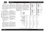
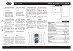
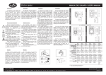
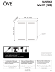
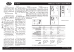
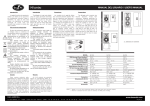
arco series
Garantía
Todos nuestros productos están
garan-tizados por un periodo de 24 meses
desde la fecha de compra. Las garantías
sólo serán válidas si son por un defecto de
fabricación y en ningún caso por un uso
incorrecto del producto. La reparación en
garantía cubre la reposición de las partes
defectuosas. Otros cargos como portes y
seguros, son a cargo del comprador en
todos los casos. Para solicitar reparación
en garantía es imprescindible que el
producto no haya sido previamente
manipulado e incluir una fotocopia de la
factura de compra.
arco 24
340
210
Wall plugs provided are to be
used in brick walls only. For other wall
materials, source the suitable wall plug
before use.
D.A.S. Audio S.A. is not
responsible for use other than the
recommended. Use only screws and
wall plugs supplied on surfaces that
will provide sufficient support. Do not
use on surfaces such as plaster and
gypsum.
140
140
Contact a licensed contractor if
there is any doubt.
150
Safety Precautions
The double square indicates Class
II device.
If the device is not IP-54 version,
do not expose to rain or moisture.
Do not place loudspeakers in
proximity to devices sensitive to
magnetic fields such as television
monitors or data sto-rage magnetic
material.
Conexión
Connection
Apague el amplificador antes de
hacer cualquier conexión. Conecte las
bornas de salida de un canal de
amplificador al conector de entrada de
las cajas acústicas utilizando cable de
altavoz.
Pele aproximádamente 1 cm de la
camisa del cable e introdúzcalo en el
terminal correspondiente de forma que
quede oculto el conductor.
Obsérvese la polaridad (rojo=+,
negro=-).
150
The exclamation point inside an
equila-teral triangle indicates the
existence of internal components
whose substitution may affect safety.
The specifications can be found
on the rear label of the product.
Switch off the amplifier before
making any connections. Connect an
amplifier’s output channel terminals to
the enclosure’s input terminals using
speaker cable.
Peel off approximately 1 cm of the
cable’s plastic jacket, depress the
terminal’s push button and insert the
cable so that the bare wire cannot be
touched.
Note polarity (red= +, black= -).
ALL DIMENSIONS IN MILIMETERS
MODEL
RMS (Average) Power
Handling (1)
Peak Power Handling(2)
Frequency Range (-10 dB)
Nominal Impedance
On-axis Sensitivity 1W/ 1m
Rated maximum Peak SPL at
1m(3)
No user serviceable parts inside.
Warranty
All D.A.S. products are warrantied
against any manufacturing defect for a
period of 2 years from date of purchase.
The warranty excludes damage from
incorrect or misuseuse of the product. All
warranty repairs must be exclusively
undertaken by the factory or any of its
authorized service centers. To claim a
warranty repair, do not open or intend to
repair the product. Return the damaged
unit, at shippers risk and freight prepaid, to
the nearest service center with a copy of
the purchase invoice.
El diagrama de bloques de la
connexión de dos altavoces a un
amplificador estéreo se muestra en el
margen izquierdo.
Debajo de este párrafo se detalla
gráficamente. Seleccione con el
conmutador
la
posición
correspondiente
a
la
potencia
deseada.
The block diagram for the
connection of two speakers to a stereo
amplifier is shown in the left margin
and is detailed graphically below.
Use the switch to select the
position that corresponds to the
required power.
HF Horn Coverage Angles
(-6 dB)
Enclosure Material
Color/Finish
Transducers/Replacement
Parts
Connectors
arco 4T
8
W
10
15W
7.5W
5W
arco 24T
8
10
W
El signo de exclamación dentro de
un triángulo indica la existencia de
componentes internos cuyo reemplazo
puede afectar a la seguridad.
Las
especificaciones
se
encuentran en la etiqueta de la parte
posterior del producto.
El doble recuadro indica equipo
Clase II.
No exponga este equipo a lluvia o
humedad (si no es versión IP-54).
No
emplace
altavoces
en
proximidad a equipos sensibles a
campos magnéticos, tales como
monitores de televisión o material
magnético de almacenamiento de
datos.
No existen partes ajustables por el
usuario en el interior de este equipo.
Los tacos suministrados son para
uso en paredes de
ladrillo, para
cualquier
otro
material
deberá
proveerse de los tacos adecuados.
D.A.S. Audio S.A. no se
responsabilizará
de
usos
no
recomendados de estos soportes, ya
sea la no utilización de los tacos o
tornillos suministrados, o la sujeción de
la caja a superficies que no tengan
suficiente resistencia a la tracción,
como son escayola y yeso, por
ejemplo.
Contacte con un instalador
autorizado si tiene cualquier duda.
arco 4
Surface precautions
8
W
20
30W
15W
W
10
5W
Precauciones de Seguridad
The new arco series is a line-up
of two way systems for
background/foreground music and
paging applications that are both
compact in size and light inweight.
Ideal for reproducing music
program in retail stores, lounges,
boutiques, board-rooms, airports
and convention centers.
Precauciones de colgado
5W
La nueva serie arco es una línea de
sistemas de dos vías, de reducidas
dimensiones y poco peso realizado en
ABS pintable de alta resistencia al
impacto.
La serie es ideal para aplicaciones
de música ambiente y megafonía en
lugares como tiendas, boutiques,
bares y cafeterías, aeropuertos y
centros deconvenciones.
Introduction
2.5
W
Introducción
MANUAL DEL USUARIO / USER’S MANUAL
8
D.A.S. AUDIO S.A.
C/ Islas Baleares, 24 - 46988 - Fuente del Jarro. Valencia - SPAIN - Tel. 96 134 05 25 - Tel. Intl. +34 96 134 08 60 - Fax +34 96 134 06 07
Dimensions (H x W x D)
Weight
Accessories
arco 4
arco 24
50 W
100 W
200 W
400 W
72 Hz- 22 kHz
65 Hz- 22 kHz
8 ohms
8 ohms
86 dB SPL
89 dB SPL
109 dB
115 dB
90º x 90º
80º x 70º
High Impact paintable
ABS+UV resistant
High Impact paintable
ABS+UV resistant
Black or white
Black or white
LF: 4G/ 4G
HF: TWT-4/ TWT-4
LF:2 x 4G4/ 4G4
HF: TWT-24/ TWT-24
Spring loaded push
terminals
Spring loaded push
terminals
21 x 14 x 14 cm
8.3 x 5.5 x 5.5 in
34 x 15 x 15 cm
13.4 x 5.9 x 5.9 in
1.6 kg (3.5 lb)
2.6 kg (5.7 lb)
AX-4RM incl.
AXU-AC4 / AXA-AC
AX-4RM incl.
AXU-AC24 / AXA-AC
(1) Based on a 2 hour test continously applying 6 dB crest factor pink noise (IECshaped)
(2) Half space (on wall)
(3) Maximum calculated Peak SPL based on sensitivity and RMS power handling
www.dasaudio.com
UM_ARC-03
arco series
MANUAL DEL USUARIO / USER’S MANUAL
AXU-AC4 / AXU-AC24
AX-4RM
El soporte AX-4RM (incluido) ha
sido diseñado para ser utilizado en
posición horizontal o vertical y puede
ser instalado techo o pared.
The AX-4RM bracket (included)
has been designed to be mounted in
horizontal or vertical position. It can
be installed on walls or ceilings.
Montaje de soporte
1.- Quitar tapas.
2.- Posicionar el soporte AX-4RM en la
pared o techo y marcar los cuatro
puntos de anclaje.
3.- Taladrar y colocar los tacos.
4.- Colocar en posición el AX-4RM y
fijarlo con los cuatro tirafondos.
5.- Fijar la inclinación del AX-4RM
mediante el tornillo allen.
6.- Atornillar (sin apretar) la caja al AX4RM.
7.- Direccionar la caja en la posición
adecuada y apretar los tornillos.
8.- Poner la tapa del AX-4RM.
Mounting instructions
1.- Remove the cover pieces.
2.- Position the AX-4RM on the wall or
ceiling and mark the drill holes.
1x
1x
2x
4x
4x
1x
Contenido del embalaje
DIN6912 M6x 12
DIN6798J M6
DIN6912 M6x 16
tornillos ø6x40mm
tacos nº 8
llave allen nº 5
3. Drill and insert the wall plugs.
4. Position the AX-4RM and attach
withscrews.
5. Angle the support and lock with the
Allen screw.
6. Screw (without tightening) the arco
4/24 to the AX-4RM.
7. Aim the unit in the desired position
and tighten the screws.
8. Place the decorative cap in place.
Package Contents
1x DIN6912 M6x 12
1x DIN6798J M6
2x DIN6912 M6x 16
4x ø6x40mm round philips headed
screws
4x n.8 wall plugs
1x n.5 allen(hex) key
El soporte en “U” AXU-AC ha sido
diseñado para ser utilizado en
posición horizontal o vertical y puede
ser instalado en techo o pared.
The AXU-AC “U” bracket has
been designed to be mounted in the
horizontal or vertical position. It can
be installed on walls or ceilings.
Montaje de soporte
1.- Quitar tapas.
2.- Posicionar el soporte AXU en la
pared o techo y marcar los puntos de
anclaje.
3.- Taladrar y colocar los tacos.
4.- Posicionar la caja entre los brazos
del soporte. Observese que el AXU
permite un giro asimétrico, por tanto
instálese según hacia donde se
pretenda girar.
5.- Atornillar sin llegar a fijar la caja al
soporte
utilizando
la
tornillería
suministrada.
6.- Direccionar la caja en la posición
adecuada y proceda al apriete de los
tornillos.
Mounting instructions
1. Remove the cover pieces.
2. Position the AXU support on the
wall or ceiling and mark the drill
holes.
3. Drill and insert the wall plugs.
4. Position the arco 4/24 between the
arms of the support. Beware that the
support
allows
for
an
AXU
asymmetric arc, install in the
appropriate direction.
5. Attach the unit to the support
using the screws supplied but do not
tighten.
6. Aim the unit in the correct position
and tighten the screws.
4x
4x
4x
4x
4x
Contenido del embalaje
DIN 6912 M6x12
DIN 7980 M6 (arandela grower)
DIN 7505-B ø5x40
DIN 125A M5 (arandela plana)
tacos nylon nº 7
4x
4x
4x
4x
4x
Package Contents
DIN 6912 M6x12
DIN 7980 M6 (lock washer)
DIN 7505-B ø5x40
DIN 125A M5 (flat washer)
wall plugs nº 7
AXA-AC
El soporte AXA-AC ha sido
diseñado para formar arrays de arco 4 y
arco 24. Instalación array horizontal en
pared: máximo de 3 cajas, con el AXU
en la del centro. Instalación array
vertical en pared: máximo de 3 cajas,
con el AXU abajo. En techo: máximo
de 6 cajas.
The AXA-AC bracket has been
designed to set up arco arrays.
Horizontal
wall
mounting
array:
maximum of 3 boxes, attachment to
the center box. Vertical wall mounting
array:
maximum
of
3
boxes,
attachment to the bottom box. Ceiling
mounting: maximum 6 boxes.
Montaje de soporte
1.- Fijar el AXU en techo o pared.
2.- Posicionar la arco 4/24 entre los
brazos del soporte AXU y 2 soportes
AXA-AC en el exterior de ambos.
Atornillar con tornillo allen y grower.
3.- Colocar la siguiente caja con un
nuevo AXA-AC a cada lado, en el
hueco entre los anteriores. El AXA-AC
permite angular de 0º a 42º en pasos
de 6º.
4.- Atornillar la siguiente caja entre los
2 AXA-AC anteriores y con 2 nuevos,
esta vez, en el exterior del conjunto.
5.- Repetir las operaciones 3 y 4.
En el caso de colgar un numero
par de cajas, se incluyen arandelas
planas para suplementar la distancia
entre el ultimo AXA-AC y la caja. Es
recomendable dos personas para el
montaje del soporte AXA-AC.
Mounting instructions
1. Attach the AXU to the wall or ceiling.
2. Position the arco 4/24 between the
support arms of the AXU-AC. Place the
AXA-AC supports on the outside of the
AXU-AC on each side of the box (as
shown). Insert allen screw and
lockwashers.
3. Place second box with a set of AXAAC supports as shown.
4. Screw boxes, selecting the angles
provided between 0º and 42º in
6ºsteps.
5. Repeat points 3. and 4. to add more
boxes.
Note: if an even number of boxes
(2, 4 or 6) are assembled in the array,
use the wide washer (incl.) to
supplement the distance between the
last box and the AXA-AC. Two person
installation is recommended.
Contenido del embalaje
4x DIN 6912 M6x12
4x DIN 7980 M6 (arandela grower)
2x DIN 9021 M6 (arandela carrocero)
Package Contents
4x DIN 6912 M6x12
4x DIN 7980 M6 (lock washer)
2x DIN 9021 M6 (washer)
AX4-RM
AXU-AC4
AXU-AC24
AXA-AC
D.A.S. AUDIO S.A.
C/ Islas Baleares, 24 - 46988 - Fuente del Jarro. Valencia - SPAIN - Tel. 96 134 05 25 - Tel. Intl. +34 96 134 08 60 - Fax +34 96 134 06 07
www.dasaudio.com