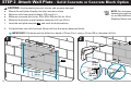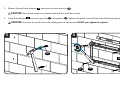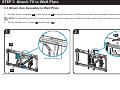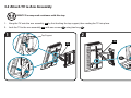
1
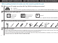
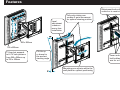
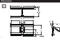
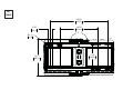
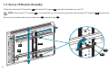
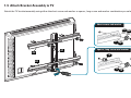
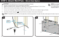
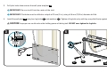
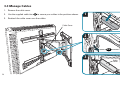
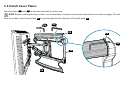
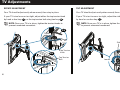
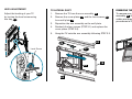
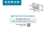
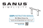
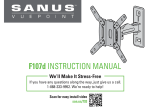
SLF 5 INSTRUCTION MANUAL
We’ll Make It Stress-Free
If you have any questions along the way, just give us a call.
1-888-333-1376 (UK: 0800-056-2853). We’re ready to help!
Scan for easy install video
http://san.us/306
IMPORTANT SAFETY INSTRUCTIONS – SAVE THESE INSTRUCTIONS – PLEASE READ ENTIRE MANUAL PRIOR TO USE
Before getting started, let’s make sure this mount is perfect for you!
1
Does your TV weigh more than 56.7 kg (125 lb) including accessories?
(56.7 kg)
125 lb
2
3
No — Perfect!
Yes — This mount is NOT compatible. Visit Simplicity.Sanus.com or call 1-888-333-1376 (UK: 0800-056-2853) to find a compatible mount.
What is your wall made of?
Drywall with
wood studs
Solid concrete or
concrete block
Perfect!
Perfect!
?
Call 1-888-333-1376 (UK: 0800-056-2853)
Do you have all of the tools needed?
5.5 mm
(7/32 in.)
4
Unsure?
10 mm
(3/8 in.)
13 mm
(1/2 in.)
Ready to begin?
Please read through these instructions completely to be sure you’re comfortable with this easy install process. Also check your TV
owner’s manual to see if there are any special requirements for mounting your TV.
If you do not understand these instructions or have doubts about the safety of the installation, assembly or use of this product, contact
Customer Service at 1-888-333-1376 (UK: 0800-056-2853).
2
Features
Adjustment knobs allow fingertip
control or to restrict movement
Level
adjustment
creates a
worry-free
installation
Fully articulating arm
creates 2-point movement
for optimal viewing position
200 x 200mm
700 x 425mm
TV bracket expands
to fit TV hole patterns
from 200 x 200mm up
to 700 x 425mm
TV tilts up
or down for
the perfect
viewing angle
Cover and cable tie holes
hold cables along mount
arm for a clean look
Mounting arm adjusts within the
wall plate for optimal positioning
3
Dimensions
in.
[mm]
29.46
748.4
1.70
43.1
12.45
316.2
28.74
730.0
27.56
700.0
6.53
165.8
15.00°
4.00°
200mm
to
425mm
9.06
230.0
0.34
8.8
4
in.
[mm]
24.00
609.6
2.00
50.8
16.00
406.4
5
R0.17
4.3
18.11
460.0
11.56
293.6
5
Supplied Parts and Hardware
WARNING: This product contains small items that could be a choking hazard if swallowed.
Before starting assembly, verify all parts are included and undamaged. If any parts are missing or damaged, do not return the damaged item to
your dealer; contact Customer Service. Never use damaged parts!
NOTE: Not all hardware included will be used.
STEP 1 Parts and Hardware
03
x4
01
x1
Vertical TV
Support
02
x2
6
05
x4
08
x4
M4 x 12mm
M4 x 35mm
M8 x 16mm
06
x4
M6 x 20mm
07
x4
M8 x 20mm
09
x4
M6 x 35mm
10
x4
12
x4
11
x4
Horizontal TV
Bracket
M6 x 12mm
04
x4
M4
13
x4
M6 / M8
M8 x 35mm
14
x4
Spacer
#8 Allen Nut
STEP 2 Parts and Hardware
15
x1
Wall Plate
Template
17
x4
STEP 3-2 Parts and Hardware
5/16 in. x 2 3/4 in.
18
x4
16
x1
Wall Plate
22
x1
STEP 3-3 Parts and Hardware
Concrete Anchors
19
x4
5/16 in.
Arm Assembly
23
x5
Cable Tie
STEP 3-4 Parts and Hardware
STEP 3-1 Parts and Hardware
20
x1
1/4-20 x 3/4 in.
24
x2
21
x4
25
x1
3/16 in.
26
x1
7/32 in.
1/4-20 x 3/8 in.
Cover Plate
7
STEP 1 Attach Brackets to TV
1-1 Select TV Screw Diameter
1-2 Select TV Screw Length
Hand thread screws into the threaded inserts
on the back of your TV to determine which
screw diameter (M4, M6, or M8) to use.
If your TV has a flat back, use the shorter screws.
Spacers and longer screws are supplied to accommodate:
● irregular / round back TVs
● TVs with inset mounting holes
● extra space needed for cables
M4
M6
CAUTION:
Verify adequate thread
engagment with the screw or
screw/spacer combination.
M8
FLAT BACK
ROUND BACK
INSET HOLES
CABLES
- Too short will not hold the TV.
- Too long will damage the TV.
Too Short
Correct
Too Long
8
1-3 Assemble TV Brackets
Slide horizontal TV brackets 02 onto the vertical TV support 01 as shown.
NOTE: Position the slotted holes toward the outside for TV hole patterns larger than 250mm and toward the inside for hole patterns 250mm or less.
01
02
Screw
posts
Angle the brackets 02
to clear the screw posts
02
01
TV Hole pattern greater than 250mm
Tilt the brackets 02 to
nest the screw posts
TV Hole pattern 250mm or less
Slotted Holes
02
Slotted Holes
9
1-4 Secure TV Bracket Assembly
Center the horizontal TV brackets 02 and vertical TV support 01 over the hole pattern on your TV.
NOTE: If the vertical TV support 01 is not centered, you may need to reposition the horizontal TV supports 02 (see previous step 1-3).
Secure the assembly with the four allen nuts 14 using hex key 25 .
02
01
14
02
25
10
1-5 Attach Bracket Assembly to TV
Attach the TV bracket assembly using either the short screw and washer or spacer, long screw and washer combination you selected for your TV.
Short screw and washer
03 04
05 06
07
11 12
02
01
Spacer, long screw and washer
13
08 09
10
02
11 12
11
STEP 2 Attach Wall Plate - Wood Stud Option
CAUTION: Avoid potential personal injuries and property damage!
●
●
●
Drywall covering the wall must not exceed 16 mm (5/8 in.)
Minimum wood stud size: common 51 x 102 mm (2 x 4 in.) nominal 38 x 89 mm (1 1/2 x 3 1/2 in.)
Minimum horizontal space between fasteners: 406 mm (16 in.)
1.
Locate studs. Verify the center of the stud(s) using an awl, a thin nail, or an edge to edge stud finder.
2.
Level the wall plate template 15 and mark the hole locations in the center of the studs.
NOTE: For assistance in
determining wall plate location,
try our MountWizard™ at
Simplicity.Sanus.com
NOTE: TV shifts 82.5 mm (3 1/2 in.) to the right when in the home position. Consider this when selecting the location of your wall mount.
2
1
≤16 mm
(5/8 in.)
406-610 mm
(16-24 in.)
15
12
3.
Drill pilot holes then remove the wall plate template 15 .
IMPORTANT: Be sure to drill into the center of the stud.
IMPORTANT: Pilot holes must be drilled to a depth of 75 mm (3 in.), using a 5.5 mm (7/32 in.) diameter drill bit.
4.
Install the wall plate 16 using four lag bolts 17 and washers 19 . Tighten all lag bolts only until they are pulled firmly against the wall plate.
CAUTION: Improper use could reduce the holding power of the lag bolt. DO NOT over-tighten the lag bolts.
3
4
75 mm
(3 in.)
5.5 mm
(7/32 in.)
15
17
19
16
13
STEP 2 Attach Wall Plate - Solid Concrete or Concrete Block Option
CAUTION: Avoid potential personal injuries and property damage!
NOTE: For assistance in
determining wall plate location,
try our MountWizard™ at
Simplicity.Sanus.com
●
●
●
●
Mount the wall plate directly onto the concrete surface
Minimum solid concrete thickness: 203 mm (8 in.)
Minimum concrete block size: 203 x 203 x 406 mm (8 x 8 x 16 in.)
Minimum horizontal space between fasteners: 610 mm (24 in.)
1.
Level the wall plate template 15 and mark the hole locations.
2.
Drill pilot holes into solid concrete. Never drill into the mortar between blocks.
IMPORTANT: Pilot holes must be drilled to a depth of 75 mm (3 in.), using a 10 mm (3/8 in.) diameter drill bit.
1
2
15
15
75 mm
(3 in.)
610 mm
(24 in.)
14
10 mm
(3/8 in.)
3.
Remove the wall plate template 15 and insert concrete anchors 18 .
CAUTION: Be sure the anchors are seated flush with the concrete surface.
4.
Install the wall plate 16 using four lag bolts 17 and washers 19 . Tighten all lag bolts only until they are pulled firmly against the wall plate.
CAUTION: Improper use could reduce the holding power of the lag bolt. DO NOT over-tighten the lag bolts.
4
3
18
16
17
19
15
STEP 3 Attach TV to Wall Plate
3-1 Attach Arm Assembly to Wall Plate
1.
Position the arm assembly 20 on the wall plate 16 by tilting the top into the wall plate channel, then rotating the bottom toward the wall.
NOTE: TV shifts 82.5 mm (3 1/2 in.) to the right when in the home position. Consider this when selecting the location of your wall mount.
2.
Secure using the four screws 21 with hex key 25 .
1
2
25
16
21
Wall Plate Channel
20
16
3-2 Attach TV to Arm Assembly
HEAVY! You may need assistance with this step.
1.
Hang the TV onto the arm assembly 20 by first hooking the top support, then resting the TV into place.
2.
Lock the TV to the arm assembly 20 with one screw 22 using hex key 25 .
1
2
Top Support
20
20
23
25
17
3-3 Manage Cables
1.
Remove the cable cover.
2.
Use the supplied cable ties 23 to secure your cables in the positions shown.
3.
Reattach the cable cover over the cables.
1
Cable
Cover
Cable Cover
2
23
3
Cable
Cover
18
3-4 Install Cover Plates
Store hex keys 25 and 26 in the slots provided, for future use.
NOTE: Before installing the cover plates, use the hex keys to make any necessary adjustments as shown on pages 20 and 21.
Bow the middle of each cover plate 24 to slip the ends into the channels of the wall plate 16 .
26
25
24
24
25
16
24
19
TV Adjustments
ROTATE ADJUSTMENT
TILT ADJUSTMENT
Your TV should adjust easily when moved, then stay in place.
Your TV should adjust easily when moved, then stay in place.
If your TV is too loose or too tight, adjust either the top tension knob
by hand or hex key 26 , or the top tension bolt using hex key 26 .
If your TV is too loose or too tight, adjust the side tension knob
by hand or use hex key 25 .
NOTE: Once your TV is in place, tighten the tension knobs to
prevent unwanted movement.
NOTE: Once your TV is in place, tighten the tension knob
to prevent unwanted movement.
26
Tighten
Loosen
26
Tighten
Side Tension Knob
Top Tension
Knob
Top Tension
Bolt
Tighten
Loosen
Loosen
25
20
LEVEL ADJUSTMENT
TV LATERAL SHIFT
REMOVING THE TV
Adjust the leveling of your TV
by turning the level screw using
hex key 25 .
1.
Remove the TV from the arm assembly 20 .
2.
Remove the cover plates 24 and the four screws 21
from wall plate 16 .
3.
Reposition the arm assembly on the wall plate.
To remove your TV from the arm
assembly 20 , disconnect all
cables and then reverse the
procedures in STEP 3-2.
4.
Reattach the four screws (STEP 3-1) and replace the
cover plates (STEP 3-4).
5.
Hang the TV onto the arm assembly following STEP 3-2.
20
24
25
21
Level Screw
20
16
25
24
21
ESPAÑOL
INSTRUCCIONES DE SEGURIDAD IMPORTANTES. CONSÉRVELAS. LEA TODO EL MANUAL ANTES DE UTILIZAR ESTE PRODUCTO.
Antes de comenzar, verifiquemos que este soporte sea perfecto para usted.
1
¿Su televisor pesa más de 56,7 kg (125 libras) incluyendo los accesorios?
(56,7 kg)
125 libras
2
3
No — ¡Perfecto!
Sí — Este soporte NO es compatible. Visite Simplicity.Sanus.com o llame al 1-888-333-1376 (Reino Unido: 0800-056-2853) para
encontrar un soporte compatible.
¿De qué está hecha su pared?
Tabiques de yeso con
montantes de madera
Hormigón sólido o
bloques de cemento
¡Perfecto!
¡Perfecto!
?
Llame al 1-888-333-1376 (Reino Unido: 0800-056-2853)
¿Tiene todas las herramientas necesarias?
5,5 mm
(7/32'')
4
22
¿No está seguro?
10 mm
(3/8'')
13 mm
(1/2'')
¿Listo para comenzar?
Lea estas instrucciones en su totalidad para estar seguro de sentirse cómodo con este fácil proceso de instalación. Consulte también
el manual del usuario de su televisor para ver si existe algún requisito especial para instalar su televisor en la pared.
Si no entiende las instrucciones o si tiene dudas acerca de la seguridad de la instalación, del ensamblado o del uso del producto,
contáctese con el servicio de atención al cliente al 1-888-333-1376 (Reino Unido: 0800-056-2853).
ESPAÑOL
Descripción
VER PÁGINA 3
La placa de sujeción se expande para adecuarse a televisores con patrones de orificios de 200 x 200 mm hasta 700 x 425 mm.
El televisor se inclina hacia arriba / abajo para obtener el ángulo de visualización perfecto.
El ajuste del nivel crea una instalación sencilla.
El brazo completamente articulado crea un movimiento de 2 puntos para una alcanzar una posición de visualización óptima.
El brazo se ajusta en la placa mural para un posicionamiento óptimo.
Las perillas de ajuste permiten el ajuste manual o limitar el movimiento.
La cubierta y los orificios para cinchos sujetan los cables a lo largo del brazo para un aspecto prolijo.
Dimensiones
VER PÁGINAS 4-5
Piezas y accesorios suministrados
VER PÁGINAS 6-7
ADVERTENCIA: Este producto contiene piezas pequeñas que, si fuesen tragadas, podrían producir asfixia.
Antes de iniciar el ensamblaje, compruebe que todas las piezas estén incluidas y en buenas condiciones. Si faltan piezas o alguna está dañada,
no devuelva el artículo al distribuidor; póngase en contacto con el servicio de atención al cliente. Nunca utilice piezas deterioradas.
NOTA: No todos los accesorios incluidos deberán utilizarse.
23
ESPAÑOL
PASO 1 Colocar las placas de sujeción en el televisor
1-1 Seleccione el diámetro de los tornillos para el televisor
VER PÁGINAS 8-11
VER PÁGINA 8
Enrosque manualmente los tornillos en los encastres roscados del dorso del televisor a fin de determinar qué diámetro de tornillos
(M4, M6 o M8) utilizar.
1-2 Seleccione la longitud de los tornillos para el televisor
VER PÁGINA 8
Si el dorso del televisor es plano, utilice los tornillos cortos. Los espaciadores y los tornillos largos se proporcionan para:
● los televisores con dorso irregular / redondeado
● los televisores con orificios de montaje intercalados
● dejar un espacio adicional para cables
PRECAUCIÓN: Verifique que el tornillo o la combinación de tornillo y espaciador enrosquen correctamente.
Si el tornillo es demasiado corto no sostendrá el televisor. Si es demasiado largo dañará el televisor.
1-3 Arme las placas de sujeción del televisor
VER PÁGINA 9
Deslice las placas de sujeción horizontales 02 sobre el soporte vertical 01 como se muestra.
NOTA: Ubique los orificios muescados hacia fuera para patrones de orificios de televisores mayores a 250 mm y hacia dentro para
patrones de orificios de 250 mm o menos.
Coloque las placas de sujeción 02 en ángulo para liberar los postes de los tornillos. Incline las placas de sujeción 02 para encajar los postes
de los tornillos.
1-4 Fije las placas de sujeción
VER PÁGINA 10
Centre las placas de sujeción horizontales 02 y el soporte vertical 01 sobre el patrón de orificios de su televisor.
NOTA: Si el soporte vertical 01 no está centrado, necesitará reposicionar las placas de sujeción horizontales 02 (ver el paso 1-3).
Fije el módulo con cuatro tuercas Allen 14 usando una llave hexagonal 25 .
1-5 Acople las placas de sujeción al televisor
VER PÁGINA 11
Acople el módulo de placas de sujeción para televisor usando ya sea la combinación de tornillo corto y arandela o espaciador, o tornillo largo
y arandela, que haya seleccionado para su televisor.
24
ESPAÑOL
PASO 2 Fijar la placa mural - Opción para montantes de madera
VER PÁGINAS 12-13
PRECAUCIÓN: Evite lesiones personales y daños materiales.
●
●
●
El yeso que recubre la pared no debe exceder los 16 mm (5/8'').
Tamaño mínimo del montante de madera: común 51 mm x 102 mm (2'' x 4'') nominal 38 mm x 89 mm (1 1/2'' x 3 1/2'').
Espacio horizontal mínimo entre los elementos de sujeción: 406 mm (16'')
1.
NOTA: Para ayudar a determinar la posición de la placa mural, pruebe nuestro MountWizard™ en Simplicity.Sanus.com
Localice los montantes. Verifique el centro de los montantes con un punzón o un clavo delgado, o bien utilice un detector de bordes
de montantes.
2.
Nivele la placa mural 15 y marque la ubicación de los orificios en el centro de los montantes.
NOTA: El televisor se desplaza 82,5 mm (3 1/2'') a la derecha cuando se encuentra en la posición inicial. Considere esto a la hora de
seleccionar la ubicación de su soporte mural.
3.
Realice los orificios guía y retire la placa mural 15 .
IMPORTANTE: Asegúrese de perforar el centro del montante.
IMPORTANTE: Los orificios deben realizarse con una mecha de 5,5 mm (7/32'') de diámetro hasta una profundidad de 75 mm (3'').
4.
Instale la placa mural 16 usando cuatro tornillos tirafondo 17 y arandelas 19 . Ajuste los tornillos tirafondo solamente hasta que queden
firmes contra la placa mural.
PRECAUCIÓN: El uso indebido podría reducir la capacidad de retención de los tornillos tirafondo. NO ajuste en exceso los tornillos tirafondo.
PASO 2 Fijar la placa mural - Opción para hormigón sólido o bloques de cemento
VER PÁGINAS 14-15
PRECAUCIÓN: Evite lesiones personales y daños materiales.
●
●
●
●
Instale la placa mural directamente sobre la superficie de hormigón.
Espesor mínimo del hormigón: 203 mm (8'')
Tamaño mínimo del bloque de cemento: 203 x 203 x 406 mm (8'' x 8'' x 16'')
Espacio horizontal mínimo entre los elementos de sujeción: 610 mm (24'')
25
ESPAÑOL
PASO 2 Fijar la placa mural - Opción para hormigón sólido o bloques de cemento (continuación)
NOTA: Para ayudar a determinar la posición de la placa mural, pruebe nuestro MountWizard™ en Simplicity.Sanus.com
1.
2.
3.
4.
Nivele la placa mural 15 y marque la ubicación de los orificios.
Realice los orificios guía en el hormigón sólido. Nunca perfore el cemento que une los bloques.
IMPORTANTE: Los orificios guía deben realizarse con una mecha de 10 mm (3/8'') de diámetro hasta una profundidad de 75 mm (3'').
Retire la placa mural 15 e introduzca los anclajes para cemento 18 .
PRECAUCIÓN: Cerciórese de que los anclajes queden nivelados respecto de la superficie de hormigón.
Instale la placa mural 16 usando cuatro tornillos tirafondo 17 y arandelas 19 . Ajuste los tornillos tirafondo solamente hasta que queden
firmes contra la placa mural.
PRECAUCIÓN: El uso indebido podría reducir la capacidad de retención de los tornillos tirafondo. NO ajuste en exceso los tornillos tirafondo.
PASO 3 Fije el televisor a la placa mural
3-1 Fijar el módulo del brazo a la placa mural
1.
2.
VER PÁGINA 16
VER PÁGINA 16
Ubique el módulo del brazo 20 sobre la placa mural 16 inclinando la parte superior dentro del canal de la placa mural, y rotando luego
la parte inferior hacia la pared.
NOTA: El televisor se desplaza 82,5 mm (3 1/2'') a la derecha cuando se encuentra en la posición inicial. Considere esto a la hora de
seleccionar la ubicación de su soporte mural.
Fije usando los cuatro tornillos 21 con la llave hexagonal 25 .
3-2 Acoplar el televisor al módulo del brazo
VER PÁGINA 17
¡ELEMENTO PESADO! Es posible que necesite ayuda en este paso.
26
1.
2.
Para colgar el televisor del módulo del brazo 20 , enganche el soporte superior y luego apoye el televisor en su lugar.
Fije el televisor al brazo 20 con un tornillo 22 usando una llave hexagonal 25 .
3-3 Organizar los cables
ESPAÑOL
VER PÁGINA 18
Retire la cubierta de los cables. 2. Utilice los cinchos sujetacables provistos 23 para fijar los cables en las posiciones que se muestran.
NOTA: Antes de instalar las tapas, use las llaves hexagonales para realizar cualquier ajuste necesario, como se muestra en las páginas 20 y 21.
Vuelva a colocar la cubierta de los cables por sobre los cables.
3-4 Instalar las tapas
VER PÁGINA 19
Guarde las llaves hexagonales 25 y 26 en las ranuras, para su uso en el futuro.
Arquee la parte media de cada tapa 24 para introducir los extremos en los canales de la placa mural 16 .
Ajustes del televisor
VER PÁGINAS 20-21
AJUSTE DE LA ROTACIÓN
El televisor debe acomodarse fácilmente al moverlo, y luego quedar en su lugar. Si el televisor está demasiado suelto o demasiado ajustado,
puede o bien ajustar la perilla de tensión superior manualmente o con la llave hexagonal 26 , o bien ajustar el perno de tensión superior con
la llave hexagonal 26 .
NOTA: Una vez que el televisor esté en su lugar, ajuste las perillas de tensión para evitar un movimiento indeseado.
AJUSTE DE LA INCLINACIÓN
El televisor debe acomodarse fácilmente al moverlo, y luego quedar en su lugar. Si el televisor está demasiado suelto o demasiado ajustado, ajuste la
perilla de tensión lateral manualmente o con la llave hexagonal 25 .
NOTA: Una vez que el televisor esté en su lugar, ajuste las perillas de tensión para evitar un movimiento indeseado.
AJUSTE DEL NIVEL
Ajuste el nivel de su televisor girando el tornillo de ajuste de nivel con la ayuda de la llave hexagonal 25 .
DESPLAZAMIENTO LATERAL DEL TELEVISOR
1: Retire el televisor del módulo del brazo 20 . 2: Retire las tapas 24 y los cuatro tornillos 21 de la placa mural 16 . 3: Vuelva a ubicar el módulo
del brazo sobre la placa mural. 4: Vuelva a colocar los cuatro tornillos (PASO 3-1) y las tapas (PASO 3-4). 5: Cuelgue el televisor del módulo del
brazo siguiendo las instrucciones del PASO 3-2.
EXTRACCIÓN DEL TELEVISOR
Para extraer el televisor del módulo del brazo 20 , desconecte todos los cables y luego revierta el procedimiento descrito en el PASO 3-2.
27
Thank you for choosing Sanus! Please take a moment to let us know how we did:
Call us: 1-888-333-1376 (UK: 0800 056 2853)
Email us: [email protected]
Leave a review: www.simplicity.sanus.com
liated corporations and subsidiaries (collectively, “Milestone”), intend to make this manual accurate and complete. However,
Milestone makes no claim that the information contained herein covers all details, conditions, or variations. Nor does it provide for every possible contingency in
connection with the installation or use of this product. The information contained in this document is subject to change without notice or obligation of any kind.
Milestone makes no representation of warranty, expressed or implied, regarding the information contained herein. Milestone assumes no responsibility for accuracy,
ciency of the information contained in this document.
©2013 Milestone AV Technologies, a Duchossois Group Company. All rights reserved. Sanus is a division of Milestone.
All other brand names or marks are used for identification purposes and are trademarks of their respective owners.
SANUS • 6436 City West Parkway • Eden Prairie, MN 55344 USA
6903-002018 01