1
INSTALLATION INSTRUCTIONS
CAUTION:
MAKE SURE POWER IS SWITCHED OFF AT SERVICE PANEL
BEFORE STARTING INSTALLATION.
that the bottom flanges are in solid contact with the bottom of the canopy or cabinet. Using
wood screws and washers (not included) secure the hood to the wood strip through the
two keyholes in the back of the hood. Using the included wood mounting screws, secure
the unit to the canopy or cabinet by driving the screws through the holes (Figure 3).
OPTIONAL ADDITIONAL SUPPORT
SECTION 1
Preparing the Insert
Wood
Mounting
Strip
1. Unpack hood from the carton and confirm that all pieces are present. In addition to
the range hood you should have:
12 -Screws (46", 58" models - 14)
2 - Halogen Bulbs (58" models - 4)
1 - Duct Adapter
1 - Grease Trough
2 - Grease Baffles (46", 58" models - 3)
1 - Instruction/Safety Sheet Figure 3
NOTE: Some hoods may be shipped with a protective plastic adhered to the underside
of the unit. It is recommended to leave this in place during installation to protect it from
scratching. Remove when the installation is complete.
SECTION 4
SECTION 2
BUILDING CODES.
Canopy
Washer
Screws
Ducting
CAUTION: ALL DUCTING MUST COMPLY WITH LOCAL AND NATIONAL
Preparing the Area
CAUTION: MAKE SURE POWER IS SWITCHED OFF AT SERVICE PANEL
BEFORE STARTING INSTALLATION.
WARNING: TO REDUCE THE RISK OF FIRE, USE ONLY METAL DUCTWORK.
1. Determine the type of ducting you will require (Figure 4).
CAUTION:
Horizontal
WHEN CUTTING OR DRILLING INTO WALL DO NOT DAMAGE
ELECTRICAL WIRING AND OTHER HIDDEN UTILITIES.
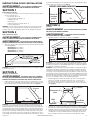
1. Cut an appropriately sized hole for the cabinet or canopy the liner will be mounted
into (Figure 1):
Model LIN34: 34.5" x 19.375"
Model LIN40: 40.5" x 19.375"
Model LIN46: 46.5" x 22.625"
Model LIN58: 58.5" x 22.625"
Roof Cap
Outlet
Adapter
34.5"/40.5"/
46.5"/58.5"
Figure 1
Wall Cap
19.375"
22.625"
NOTE: The hood must be mounted a minimum of 24" and a maximum of 36" from the
cooking surface.
SECTION 3
Mounting the Liner
CAUTION:
DUE TO THE WEIGHT AND BULK OF THE UNIT, IT IS RECOMMENDED
THAT THREE PEOPLE ARE PRESENT DURING INSTALLATION TO LIFT, HOLD, AND SECURE
THE UNIT IN PLACE.
1.
Flange
Lift unit up into position so that the bottom flanges are in solid contact with the bottom
of the canopy or cabinet. Using the included wood mounting screws, secure the unit
to the canopy or cabinet by driving the screws through the holes (Figure 2).
Figure 4
Vertical
NOTE: For models using the B600 blower (LIN34, LIN40), a minimum of 6” diameter
outlet adapter & ducting is required to achieve the proper air flow. The B1125 (LIN46,
LIN58) requires a minimum 10” diameter adapter and ducting.
NOTE: When the duct termination is similar to that shown in Figure 4 (passing through
the wall to which the hood is mounted) the installation requires special consideration.
Depending upon where the wall studs are located, it may be necessary to cut one
or more of the wall studs and install a header and footer to transfer the load to the
adjacent studs. Additional studs may need to be framed into the opening to attach dry
wall or secure the hood. If this is your situation Air King recommends that you hire a
professional and comply with all applicable codes.
2. Install the proper sized outlet adapter to the hood by matching up the four holes on
the flange of the adapter to the four corresponding holes on the hood and secure
in place with the provided screws. Ensure an airtight seal around the adapter by
securing all connections with ducting tape (Figure 5).
Ducting
Outlet Adapter
Canopy
Screws
Screws
Hood
Flange
Figure 5
Figure 2
NOTE: If additional support is required, install a 2" x .75" strip of wood (34" wide) between
the back of the canopy (rear wall) and the hood. When installing the wood strip to the
back of the canopy, locate studs in the wall to support the weight of the canopy. Center
the wood strip 11.5" from the bottom of the canopy and attach the strip to at least two
studs in the rear wall (do not fasten the strip to drywall only). Lift unit up into position so
6728024 Rev. C 8-10
Flange
3
When there is access to the top of the unit, connect the ducting to the duct collar
and secure in place using tape to seal all joints (Figure 5).
4. When there is no access to the top of the hood, carefully pull down the metal duct
through the custom hood base hole. Slide this duct over the duct collar. Make sure
the adapter/damper assembly enters the ducting. Seal the connection with duct tape.
www.airkinglimited.com
2 of 8