1
SECTION 5
Top
Channel
Wiring
CAUTION:
ALL ELECTRICAL CONNECTIONS MUST BE MADE IN
ACCORDANCE WITH LOCAL CODES, ORDINANCES, OR NATIONAL ELECTRICAL
CODE. IF YOU ARE UNFAMILIAR WITH METHODS OF INSTALLING ELECTRICAL
WIRING, SECURE THE SERVICES OF A QUALIFIED ELECTRICIAN.
1.
2.
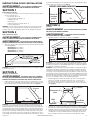
Remove the two wire compartment cover screws
to gain access into the wire compartment (Figure
6). Connect the white wire from the range hood to
the white wire from the supply, and the black wire
from the range hood to the black wire of the supply.
Connect the ground wire from the home (green or
bare) to the ground wire (green) from the hood. Use
approved methods for all connections (Figure 7).
Replace the wire compartment cover and tighten
screws. Make sure all wiring is securely contained
within the wire compartment. If the quick connect
wire connector was removed from the receptacle,
replace. The connector will only fit one way into
the receptacle (Figure 6).
2
Bottom
Channel
Wire Connector
3
1
Figure 9
SECTION 8
Screws
Operation
Controls
Your Range Hood is equipped with two rotary switches with one controlling the lighting
and the other controlling the exhaust fan blower. The light switch has three positions,
High, Low, and Off. The fan switch has four positions, Off, High, Medium, and Low (Figure 10).
Figure 6
Light Switch
Hot (Black)
Supply from house
Blower Switch
Neutral
(White)
Figure 10
Ground
(Green or Bare)
SECTION 9
Figure 7
Maintenance
CAUTION:
MAKE SURE POWER IS SWITCHED OFF AT SERVICE PANEL
BEFORE SERVICING THE UNIT.
SECTION 6
Installing the Blower
1. Refer to the instructions included with the specific blower you have chosen for
installation.
SECTION 7
Finishing the Installation
1. Install the proper lighting for your specific unit:
Halogen Lamps: Use PAR16, 45W maximum lamps. Install by inserting lamp into
socket and turning clockwise until lamp is firmly seated. DO NOT over tighten.
2. If the included removable grease trough is not already installed within the hood,
insert into the rear inside channel of the hood. Make sure the taller side of the
trough is facing towards the back of the hood (Figure 8).
Grease Trough
Grease Baffles
Included with your range hood are stainless steel grease baffles along with a grease
trough that should be washed at least once a month. The baffles and trough are dishwasher
safe and should be washed in a mild soap or detergent. Reverse the instruction in
SECTION 8 Finishing the Installation, to remove baffles and trough. If the grease baffles
become damaged, replace with Air King Model PHGB1 Grease Baffles.
CAUTION:
ALLOW BULB TO COOL BEFORE REPLACING.
Changing the Lamps
Remove the lamp by turning slightly counter-clockwise and pulling out of the socket.
Replace with a PAR16 45W maximum Halogen lamp.
Fuse
To replace the fuse, turn the fuse cap located next to the wire connector counter
clockwise and pull out. Replace with the proper fuse specific to your blower. Reinstall
the fuse back into the hood.
Cleaning
CAUTION:
DO NOT USE GASOLINE, BENZINE, THINNER, HARSH CLEANSERS,
ETC., AS THEY MAY DAMAGE THE RANGE HOOD.
Channel
1.
Clean your power unit with a mild detergent, such as dishwashing liquid, and dry with
a soft cloth. NEVER USE ANY ABRASIVE PADS OR SCOURING POWDERS. Completely
dry before restoring power. NEVER IMMERSE ELECTRICAL PARTS IN WATER.
2. The fan assembly can be vacuumed when build up (dirt, lint, etc.) accumulates
over time. The fan is permanently lubricated and does not require oiling.
Figure 8
3. Install the baffle filters by inserting the top of the filter into the top channel of the
hood, then slide the bottom of the filter into the bottom channel. The filters have a
top and a bottom. The bottom of the filter will have small drain holes. These holes
must be facing down towards the grease trough to be effective (Figure 9).
6728024 Rev. C 8-10
www.airkinglimited.com
3 of 8