1
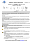
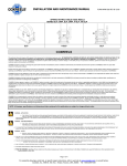
INSTALLATION AND MAINTENANCE MANUAL FORM #PM-004 REV D12/09 MOTORIZED HOSE/CABLE REELS: SERIES: 1125, 1125WC, 1175, 1185, 1195, 1275 SERIES: 1125, 1125WC, 1175-6, 1185, 1195 SERIES: 1275 COXREELS The technical data and images which appear in this manual are for informational purposes only. NO WARRANTIES, EXPRESS OR IMPLIED, INCLUDING WARRANTIES OF MERCHANTABILITY OR FITNESS FOR A PARTICULAR PURPOSE, ARE CREATED BY THE DESCRIPTIONS AND DEPICTIONS OF THE PRODUCTS SHOWN IN THIS MANUAL. COXREELS makes no warranty (and assumes no liability) as to function of equipment or operation of systems built according to customer design or of the ability of any of its products to interface, operate or function with any portions of customer systems not provided by COXREELS. COXREELS agrees to repair or exchange the goods sold hereunder necessitated by reason of defective workmanship and material discovered and reported to COXREELS within two years after shipment of such goods to Buyer. Except where the nature of the defect is such that it is appropriate, in COXREELS’ judgment, to effect repairs on site, COXREELS’ obligation hereunder to remedy defects shall be limited to repairing or replacing (at COXREELS’ option) FOB point of original shipment, any part returned to COXREELS at the risk and cost of Buyer. Defective parts replaced shall become the property of COXREELS. COXREELS shall only be obligated to make such repair or replacement if the goods have been used by Buyer only in service recommended. COXREELS is not responsible for defects which arise from improper installation, neglect, improper use of or from normal wear and tear. COXREELS obligation shall be limited by the manufacturer’s warranty (and is not further warranted by COXREELS) for all parts procured from others according to published data, specifications or performance information not designed by COXREELS. COXREELS further agrees to replace or at COXREELS’ option to provide a refund of the sales price of any goods that do not conform to applicable specifications or which differ from that agreed to be supplied which non-conformity is discovered and forthwith reported to COXREELS within 30 days after shipment to the Buyer. COXREELS’ obligation to replace or refund the purchase price for nonconforming goods shall arise once Buyer returns such goods FOB point of original shipment by COXREELS at the risk and cost of Buyer. Goods replaced by COXREELS shall become property of COXREELS. COXREELS liability on any claim, whether in contract, tort (including negligence), or otherwise, for any loss or damage arising out of, connected with, or resulting from the manufacture, sale, delivery, resale, repair, replacement or use of any products or services shall in no case exceed the price paid for the product or services or any part thereof which give rise to the claim. In no event shall COXREELS be liable for consequential, special, incidental or other damages, nor shall COXREELS be liable in respect of personal injury or damage to property not the subject matter hereof unless attributable to gross misconduct of COXREELS, which shall mean an act or omission by COXREELS demonstrating reckless disregard of the foreseeable consequences thereof. COXREELS is not responsible for incorrect choice of models or where products are used in excess of their rated and recommended capacities and design functions or under abnormal conditions. COXREELS assumes no liability for loss of time, damage or injuries to property or persons resulting from the use of COXREELS products. Buyer shall hold COXREELS harmless from all liability, claims, suits and expenses in connection with loss or damage resulting from operation of products or utilization of services, respectively, of COXREELS and shall defend any suit or action which might arise there from in Buyer’s name – provided that COXREELS shall have the right to elect to defend any such suit or action for the account of Buyer. The foregoing shall be the exclusive remedies of the Buyer and all persons and entitles claiming through the Buyer. NOTE: All designs, specifications, and dimensional data contained in this publication are subject to change without notice. WARNING – APPLICATION THE PRODUCTS IN THIS INSTALLATION AND MAINTENANCE MANUAL HAVE BEEN TESTED UNDER CONTROLLED LABORAROTY CONDITIONS TO MEET SPECIFIC TEST CRITERIA. THESE TESTS ARE NOT INTENDED TO REFLECT THE PERFORMANCE OF THE PRODUCTS OR ANY OTHER MATERIAL IN ANY SPECIFIC APPLICATION, BUT ARE INTENDED TO PROVIDE THE USER WITHY APPLICATION GUIDELINES. THE PRODUCTS ARE INTENDED FOR USE BY KNOWLEDGEABLE PERSONS HAVING THE TECHNICAL SKILL NECESSARY TO EVALUATE THEIR SUITABILITY FOR SPECIFIC APPLICATIONS. WARNING – USER RESPONSIBILITY THE USER, THROUGH ITS OWN ANALYSIS AND TESTING, IS SOLELY RESPONSIBLE FOR MAKING THE FINAL SELECTION OF THE SYSTEM AND COMPONENTS AND ASSURING THAT ALL PERFORMANCE, ENDURANCE, MAINTENANCE, SAFETY AND WARNING REQUIREMENTS OF THE APPLICATION ARE MET. TO THE EXTENT THAT COXREELS PROVIDE COMPONENT OR SYSTEM OPTIONS BASED UPON DATA OR SPECIFICATIONS PROVIDED BY THE USER, THE USER IS RESPONSIBLE FOR DETERMINING THAT SUCH DATA AND SPECIFICATIONS ARE SUITABLE AND SUFFICIENT FOR ALL APPLICATIONS AND REASONABLY FORESEEABLE USES OF THE COMPONENTS OR SYSTEM. WARNING – SAFETY READ ALL SAFETY INSTRUCTIONS CAREFULLY BEFORE ATTEMPTING TO INSTALL, OPERATE, OR MAINTAIN THIS PRODUCT. ONLY QUALIFIED PERSONNEL SHOULD UNDERTAKE THE INSTALLATION AND COMMISSIONING OF THIS PRODUCT. FAILURE TO COMPLY WITH INSTRUCTIONS COULD RESULT IN PERSONAL INJURY AND/OR PROPERTY DAMAGE. FAILURE TO FOLLOW RECOMMENDED APPLICATION INFORMATION AND RECOMMENDED PROCEDURES FOR SELECTION, INSTALLATION, CARE, MAINTENANCE AND STORAGE OF REEL ASSEMBLY, SWIVEL, HOSE, COUPLINGS OR HOSE ASSEMBLIES MAY RESULT IN FAILURE TO PERFORM PROPERLY AND MAY RESULT IN DAMAGE TO PROPERTY AND SERIOUS BODILY INJURY. FOLLOW GOOD MAINTENANCE PRACTICES – ESTABLISH A PROGRAM OF INSPECTION, TESTING AND REPLACEMENT OF REEL COMPONENTS FROM FACTORS INCLUDING: o SEVERITY OF APPLICATION, FREQUENCY OF EQUIPMENT USE, AND PAST PERFORMANCE OF REEL COMPONENTS ONLY PROPERLY TRAINED PERSONS SHOULD INSPECT, TEST OR SERVICE REEL AND HOSE/CABLE ASSEMBLIES. PERIODIC UPDATING OF TRAINING IS RECOMMENDED. DOCUMENT MAINTENANCE, INSPECTIONS AND TESTING. PROP 65 WARNING: Handling of brass material on this product exposes you to lead, a chemical known to the State of California to cause birth defects or other reproductive harm. “WASH HANDS AFTER USE” Page 1 of 5 For assembly drawings, parts lists, or specific repair instructions, refer to web site at www.coxreels.com or consult factory. Coxreels, Inc., 5865 S. Ash Ave., Tempe, Arizona, USA, 85283 Tel: 1-800-269-7335 INSTALLATION AND MAINTENANCE MANUAL FORM #PM-004 REV D 12/09 SAFETY PRESSURE WARNINGS • • • Customer Service for hose specific data). Hose reels should not be used at temperatures below or above the rating of the hose. The operational rating of a reel not equipped with hose is determined by the capacity of the installed hose. The pressure rating of the reel without hose must not be greater than the than the operational capacity of a reel. (Please refer to the COXREELS catalog, website or contact Customer Service for reel/hose specific data). Variations in the OD of higher rated hose will affect the operational capacity of the reel. • This equipment should be properly installed before use in accordance with local codes and ordinances. The pressure from the hose reel should be disconnected from the hose reel before any service functions are performed. This hose reel must not be used for pressure greater that the rating listed in the COXREELS catalog / website www.coxreels.com. OPERATIONAL WARNINGS LABELS & MARKINGS • • • • Exercise care when handling the hose reel during normal operation. Do not use hose different from that for which the reel is intended. Changes in diameter, weight per foot, length of hose or flexibility (Minimum Bend Radius) will affect the operation of the reel. Mounting hardware and fasteners should be installed to maintain tightness under vibration and checked periodically to ensure tightness. Overhead installation mountings should be such that the reel is not supported by bolts in tension. A safety chain, cable, enclosure or netting is strongly recommended to minimize damage and/or possible injury in the event of a mounting failure. Hose Reels with and without hose • MAINTENANCE WARNINGS • Modification of the equipment may cause excessive wear and will void the warranty. Contact COXREELS regarding changes or modifications of equipment which could affect reliability or safety. The marking of the hose reel provide with or without hose includes the following o The label on the frame includes the COXREELS name and Logo, the product catalog number, the individual product serial number, PSI rating and what type and length of hose intended for use on the reel. o The maximum pressure rating for every hose reel supplied without house is marked on the COXREELS Identification Label. In absence of this information, refer to website, catalog, or customer service. Actual rating is determined by the installed hose and is not to exceed the indicated maximum operational rating. The pressure rating of the hose installed on reels provided without hose must be marked on the label upon installation. PERSONAL SAFETY SPECIFICATIONS & LISTINGS • • • • The identified Series of Hose Reel products within this manual are not certified or listed by any independent certifying or regulatory body. This series of hose reels is intended for industrial use and are provided with permanent mounting means. • • • PRESSURE & TEMPERATURE RATING • • • • • • All reels covered in this manual with or without hose have specific P.S.I. ratings. (Please refer to the COXREELS catalog, website or contact Customer Service for Reel specific data). Reels should not be used at pressures greater that the rating of the hose. Multipurpose hose is installed with tube compounded for maximum oil resistance. Hose can be used for air, water, oil and many other chemical applications. Operational temperature ranges vary across the wide range of hose options. (Please refer to the COXREELS catalog, website or contact Ensure reel has been properly installed before connecting supply line. Before connecting to reel, be certain supply line does not exceed rated pressure of the hose reel or amperage rating on cable reel. Thoroughly review the “Hose Installation” instructions to properly install hose. Perform “Operational Check” per instructions to ensure reel is operating properly. If a leak should occur after applying pressure to the reel, immediately discontinue supply line pressure. Be aware of other persons and machinery in work area Do not wear loose fitting clothing when using reel Routinely check for loose, frayed, or broken wires before operating. WARNING: Prevent static sparking. When working around flammables, ensure that the hose reel, hose, and equipment are properly grounded. INSTALLATION FIGURE 1.0 FIGURE 2.0 FIGURE 3.0 Page 2 of 5 For assembly drawings, parts lists, or specific repair instructions, refer to web site at www.coxreels.com or consult factory. Coxreels, Inc., 5865 S. Ash Ave., Tempe, Arizona, USA, 85283 Tel: 1-800-269-7335 INSTALLATION AND MAINTENANCE MANUAL FORM #PM-004 REV D 12/09 WARNING: READ THESE INSTRUCTIONS CAREFULLY BEFORE ATTEMPTING TO INSTALL, OPERATE, OR MAINTAIN THIS PRODUCT. ONLY QUALIFIED PERSONNEL SHOULD UNDERTAKE THE INSTALLATION AND COMMISSIONING OF THIS PRODUCT. FAILURE TO COMPLY WITH INSTRUCTIONS COULD RESULT IN PERSONAL INJURY AND/OR PROPERTY DAMAGE. WARNING: REEL SHOULD NOT BE INSTALLED ABOVE 15 FEET MAXIMUM FROM THE FLOOR. MOUNTING OF REEL • • • INSTALLATION OF OUTLET HOSE NOTE: Before proceeding, ensure that you are installing the proper size, length and type of hose that the reel is rated for. Consult factory if unsure of rating. Overhead installation mountings should be such that the reel is not supported by bolts in tension. A safety chain, cable, enclosure or netting is strongly recommended to minimize damage and/or possible injury in the event of a mounting failure. To mount reel to a solid structure use 7/16” or M12 bolts, washers, and nuts. Masonry bolts may be used depending on mounting application. Mounting hardware is NOT provided. Mounting patterns will vary depending on model. Fit mounting hardware to ceiling/wall/floor so reel can be fastened into position. Fit reel and tighten all hardware securely. • • • • INSTALLATION OF INLET HOSE • Apply thread sealant to inlet hose and connect to the swivel joint on reel. CAUTION: FULLY EXTEND AND CHARGE HOSE BEFORE INITIALLY WINDING ON TO REEL. THIS PREVENTS FLATTENING OF HOSE AND EXCESSIVE PRESSURE ON DRUM WHEN HOSE IS FULLY CHARGED DURING OPERATION. CAUTION: IT IS IMPORTANT TO USE A “FLEXIBLE” INLET HOSE. DO NOT USE SOLID PIPING OR RESTRAIN INLET HOSE AS TO CAUSE ANY SIDE FORCE ON SWIVEL JOINT. THE WARRANTY IS VOID IF NOT PROPERLY INSTALLED. • Securely install hose reel prior to installing outlet hose. Apply thread sealant to male hose fitting and insert into the drum opening. Note: It is recommended that a swivel type connector be used to ease installation of outlet hose. Thread male hose fitting into outlet riser(s). Refer to figure 1.0 for single and figure 2.0 for double outlets. Note: Outlet riser is removable on 1195 series. Using a wrench, firmly hold on to riser fitting while tightening hose connector. • • Flush some product through the system before connecting inlet hose to the source. Connect end to supply source. Wind hose on to reel; operator should hand guide the hose on to reel to achieve maximum capacity. Flush fluid through system. Inspect hose, connections, and swivel for leaks. INSTALLATION OF CABLE (1125WC SERIES) HOOK-UP ELECTRICAL MOTOR NOTE: Before proceeding, ensure that you are installing the proper size, length and type of hose that the reel is rated for. Consult factory if unsure of rating. CAUTION: REMOVE ALL ELECTRICAL POWER WHEN WIRING. DO NOT HOT WIRE. OBSERVE ALL APPLICABLE NEC, OSHA, AND LOCAL CODES. • CAUTION: ENSURE THAT THE CABLE CONNECTOR IS SECURELY CRIMPED, SOLDERED, OR CLAMPED TO CABLE. • • • • • Place connector over stud (fig 3.0) and install brass nut (supplied). Using a wrench, firmly hold onto the nut under the connector while tightening the outer nut. Connect the supply line in the same manner. • Ensure motor location is conducive to mounting or operating requirements. Field modifications are not recommended. Ensure power supply and motor voltage ratings are compatible. Refer to figures 4.0, 5.0, and 6.0 for wiring diagrams. Install switch, solenoid, circuit breaker, etc. as required. Consult factory for optional components. Apply power, and inspect reel to determine proper operation. FIGURE 4.0 “E/ED” MOTOR DIAGRAM (SINGLE POLE SINGLE THROW) Page 3 of 5 For assembly drawings, parts lists, or specific repair instructions, refer to web site at www.coxreels.com or consult factory. Coxreels, Inc., 5865 S. Ash Ave., Tempe, Arizona, USA, 85283 Tel: 1-800-269-7335 INSTALLATION AND MAINTENANCE MANUAL FIGURE 5.0 “EA” MOTOR DIAGRAM (DOUBLE POLE SINGLE THROW) FORM #PM-004 REV D 12/09 FIGURE 6.0 “EA” MOTOR DIAGRAM (TRIPLE POLE SINGLE THROW) HOOK-UP AIR MOTOR CAUTION: DO NOT EXCEED 100 PSI MOTOR INLET PRESSURE. USE AN FRL OR CONTROL VALVE (IN LINE) TO ADJUST SPEED. • • • • • • • NOTE: Swivels designs vary depending on the reel model. Refer to repair procedure shipped with individual seal replacement kits or consult factory. A suitable sized filter/regulator/lubricator must be installed in the compressed air line within 3-6 ft. from the motor. Use pipes that are the same size as the motor ports for lengths up to 6 ft. from the main line and pipes that are larger for lengths that are longer than 6 ft. Remove plastic plugs from two ports in motor and follow steps for muffler or 4-way valve / muffler installation. A muffler (provided) must be connected to the outlet port on single rotation applications. When motor is going to be driven in both directions, a 4-way valve (not included) may be used by being connected to both ports of the motor. Muffler must then be connected to the air outlet pipe or valve port. Do not use thread tape to seal pipe threads. Use only the correct pipe sealant on the threads. This motor requires LUBRICATION. Use GAST lubricating oil part number UK5220 or equivalent. Fill reservoir to correct level. Apply air pressure, and inspect reel to determine proper operation. CAUTION: Release line pressure prior to making any repairs or adjustments to the reel. CHAIN REPLACEMENT (1175-1195 Only) • • • Remove motor as instructed. See “Motor Replacement”. Remove chain master‐link. Install new chain. Adjust chain tension and install motor as instructed. See “Motor Replacement”. MOTOR REPLACEMENT CAUTION: Before replacing motor, remove electrical or fluid pressure from reel. SWIVEL SEAL REPLACEMENT • • • • • • • • Remove inlet hose from swivel. Remove swivel from reel by unscrewing swivel from shaft. Disconnect hose from swivel. Remove retaining ring on swivel; pull out shaft from body. Replace the seals, lubricate and reassemble swivel. Fit hose to swivel then fit swivel to reel. Do not over-tighten. Reconnect inlet hose and test for leakage. • Fig 7.0 1125/1275 Series Fig 8.0 1175-1195 Series NOTE: 1125/1275 series are direct gear driven and 1175 series is chain and sprocket driven. • Disconnect wiring/fluid line pressure from motor. Remove bolts securing motor and/or bracket to reel. See figures 7.0 or 8.0 depending on reel model. Install replacement motor. Align gears or chain/sprocket depending on reel model. NOTE: Improperly engaged gears will reduce gear life. • If gear driven reel, adjust motor into location and secure in position with best gear alignment. Noise level is noticeably higher when gear is not fully engaged. If chain driven reel, adjust tension on chain to allow between ¼ to ½” play in chain. NOTE: Over-tensioning of chain will reduce motor life. • • • GEAR REPLACEMENT (1125/1275 Series Only) Remove motor as instructed above. Remove gear from shaft on motor by loosening set screws. Install new gear on to shaft. Install motor as described above. • • • • SLIP RING BRUSH REPLACEMENT (1125WC SERIES) Remove cable completely from drum of reel. Remove access panel on drum by removing four screws. Remove brush retaining nut to access worn brushes. Replace with new copper brushes. Reverse above procedure to re‐assemble reel. Page 4 of 5 For assembly drawings, parts lists, or specific repair instructions, refer to web site at www.coxreels.com or consult factory. Coxreels, Inc., 5865 S. Ash Ave., Tempe, Arizona, USA, 85283 Tel: 1-800-269-7335 INSTALLATION AND MAINTENANCE MANUAL FORM #PM-004 REV D 12/09 TROUBLE SHOOTING GUIDE TROUBLE CAUSE REMEDY HOSE/CABLE WILL NOT FULLY FIT ON TO DRUM OF REEL a) Hose/cable is longer than specified. b) Outside diameter of hose is larger than specification. c) Hose/cable was not hand guided onto reel and wound up evenly on drum. a) Cut down hose/cable to meet reels specified capacity. b) Replace hose with a hose that meets the specified maximum outside diameter requirements. c) Hand guide hose/cable on to drum as it is wound on to the reel. IT IS VERY DIFFICULT TO PULL HOSE OFF REEL ON 115Vac REEL Wiring for motor is reversed. Refer to wiring diagram and correct motor wiring. NO ELECTRICAL CURRENT AT OUTPUT END OF CABLE. (1125WC SERIES ONLY) a) Cable is severed. b) Slip ring brushes are worn. a) Replace cable. b) Replace slip ring brushes. Note: Ensure current does not exceed rated amperage. DRUM OF REEL IS CRUSHED OR DAMAGED. Hose was not charged when initially installed on to reel. Replace damaged drum. Contact factory. Install hose per instructions. FLUID PATH (PLUMBING AND/OR SWIVEL) IS LEAKING OR DAMAGED. a) Maximum pressure rating for reel has been exceeded. b) Application is not compatible with plumbing and/or swivel seal materials. a) Replace or repair damaged components. Consult factory. Check maximum pressure rating of reel. b) Contact factory to determine chemical compatibility or environmental issues (i.e. temperature rating). FLUID LEAKS FROM SWIVEL Swivel seals are damaged or worn. Replace swivel seals. See "Swivel Seal Replacement". Caution: Be sure leak is not at Hose Fitting! Page 5 of 5 For assembly drawings, parts lists, or specific repair instructions, refer to web site at www.coxreels.com or consult factory. Coxreels, Inc., 5865 S. Ash Ave., Tempe, Arizona, USA, 85283 Tel: 1-800-269-7335 FORME # Pm-004 Tour D 12/09 MANUEL D'INSTALLATION ET D'ENTRETIEN ENROULEURS MOTORISÉS DE TUYAU/CABLE : SÉRIE : 1125, 1125WCL, 1175-6, 1185, 1195, 1275 SÉRIE : 1125, 1125WCL, 1175-6, 1185, 1195 SÉRIE : 1275 LISEZ LES INSTRUCTIONS ATTENTIVEMENT AVANT INSTALLER, ACTIONNER OU MAINTENIR CE PRODUIT. SEULEMENT LE PERSONNEL QUALIFIÉ DEVRAIT ENTREPRENDRE INSTALLATION ET LA COMMISSION DE CE PRODUIT. NE PAS RESPECTER LES INSTRUCTIONS PEUT CAUSER DES BLESSURES ET/OU LA DESTRUCTION DE BIENS MATERIAUX. SÛRETÉ PERSONNELLE 1.) Assurez-vous que l’enrouleur soit correctement installé avant de relier le câble d'alimentation. 2.) Avant de connecter l’enrouleur, soyez certain que le câble d'alimentation n'excède pas la pression évaluée de la bobine. 3.) Lisez attentivement les instructions "d'installation de tuyau”. 4.) Si une fuite se produit après l’application de la pression sur l’enrouleur, discontinuez immédiatement la pression dans le câble d’alimentation. 5.) Soyez attentif (ve) à d'autres personnes et machines qui sont dans la zone de travail. 6.) Ne portez pas des vêtements trop larges quand vous utilisez l’enrouleur. 7.) Avant de commencer vérifiez s’il y a des fils lâches, frangés, ou cassés. 8.) Attention : Empêchez l'étincellement de charge statique en travaillant autour des matériaux inflammables. 3.) ATTENTION : PROLONGEZ LE TUYAU ENTIÈREMENT ET CHARGEZ LE TUYAU AVANT DE L'ENROULER . CECI EMPÊCHE L'APLATISSEMENT DU TUYAU ET DE LA PRESSION EXCESSIVE SUR LE TAMBOUR QUAND LE TUYAU EST ENTIÈREMENT CHARGÉ LORS DU FONCTIONNEMENT. 4.) Roulez te tuyau sur l’enrouleur. L'opérateur devrait guider le tuyau manuellement sur l’enrouleur pour attendre la capacité au maximum. INSTALLATION DU TUYAU D'ADMISSION 5.) Rincez du fluide dans le système. Vérifiez le tuyau, les raccordements et le pivot pour trouver des fuites. INSTALLATION DU CÂBLE (SÉRIE 1125WC) 1.) Appliquez du mastic au tuyau d'admission et connectez-le au pivot d’articulation de l’enrouleur. ATTENTION : IL EST IMPORTANT D’UTILISER UN TUYAU D'ADMISSION FLEXIBLE. N’EMPLOYEZ PAS LA TUYAUTERIE SOLIDE. NE CONTRAINEZ PAS LE TUYAU D'ADMISSION POUR NE PAS APPLIQUER UNE FORCE LATÉRALE SUR LE PIVOT D’ARTICULATION. LA GARANTIE DEVIENS NULE SI L’ENROULEUR N’EST PAS CORRECTEMENT INSTALLÉ 2.) . Rincez du produit dans le système avant de connecter le tuyau d'admission à la source. Connectez l'extrémité à la source d'alimentation. Filetez l'ajustage de précision masculin de tuyau dans le riser(s) de sortie. Regardez schéma 1.0 pour des sorties individuelles et schéma 2.0 pour des sorties doubles. Tenez fermement l'ajustage de précision avec une clé en serrant le connecteur de tuyau. MONTAGE DE L’ENROULEUR 1.) Pour monter l’enrouleur à une structure solide vous aurez besoin de boulons M12 de 7/16", de rondelles et de écrous. Des boulons de maçonnerie peuvent être utilisés selon l'application de support. Le matériel de montage n'est pas fourni. Les possibilités de montage changeront selon le modèle. Installez des pièces de montage dans le plafond/ le plancher ou le mur de telle manière que l’enrouleur puisse être glissé en place. Mettez l’enrouleur en place et serrez toute la visserie solidement. 2.) INSTALLATION DE TUYAU DE SORTIE NOTE : Avant de commencer, assurer-vous que vous installiez la taille, la longueur et le type approprié de tuyau pour lesquels l’enrouleur a été évalué. Consultez l'usine si vous n’etes pas certain de l'estimation. 1.) Installez l’enrouleur solidement avant d'installer le tuyau de sortie. 2.) Appliquez le mastic à l'ajustage de précision et à l'insertion masculins de tuyau dans l'ouverture de tambour. Note : On recommande qu'un type connecteur de pivot soit employé pour soulager l'installation du tuyau de sortie. NOTE : Avant de commencer, rassurez-vous que vous installiez la bonne taille, longueur et type de tuyau pour lequel l’enrouleur a été classé. Regardez l'étiquette pour déterminer l'ampérage. ATTENTION : ASSUREZ VOUS QUE LES CONNECTEURS DU CÂBLE SOIT SOLIDEMENT SERTIS PAR REPLIS, SOUDÉ, OU MAINTENU AU CÂBLE. 1.) 2.) 3.) Placez le connecteur au-dessus du goujon (figure 2.0) et installez l'écrou en laiton (fourni). Tenez fermement l'écrou avec une clé sous le connecteur tout en serrant l'écrou externe. Connectez le câble d'alimentation de la même manière. FORME # Pm-004 Tour D 12/09 MOTEUR ÉLECTRIQUE DE CONJUGAISON ATTENTION : COUPEZ TOUT LE COURANT ÉLECTRIQUE QUAND VOUS INSTALLEZ LES CABLES. N’INSTALLEZ PAS LE CABLE DIRECTEMENT. RESPECTEZ TOUS LES PREVISIONS DE „NEC”, „OSHA” ET LES CODES LOCAUX. 1.) 2.) 3.) 4.) 5.) Assurez-vous que le placement de moteur favorise le montage ou les exigences d'exploitation. Des modifications ne sont pas recommandées. Assurez-vous que la source d'énergie et les estimations de tension de moteur soient compatibles. Regardez les schémas 3.0, 4.0, et 5.0 pour des diagrammes de câblage. Installez le commutateur, le solénoïde, disjoncteur, etc. comme requis. Consultez l'usine pour les composants supplémentaires. Pour les séries 600 et 800, un frein de tension est fourni. Regardez le schéma 9.0 de la page suivante. Ajustez dans le sens horaire pour ajouter de la tension et dans le sens contraire pour réduire la tension. Il faut laisser une légère drague. Branchez au courant et inspectez l’enrouleur pour déterminer l'opération correcte. MONTAGE DU MOTEUR AVEC DE L’AIR ATTENTION : NE DEPASSEZ PAS 100 LIVRES PAR POUCE CARRÉ DU MOTEUR DE PRESSION D'ADMISSION. UTILISEZ UN FRL OU UNE SOUPAPE (EN LIGNE) POUR AJUSTER LA VITESSE. 1) Un filtre /régulateur/lubrificateur d’une dimension convenable doit être installé dans la ligne comprimée d'air au moins de 3-6 pieds du moteur. 2) Utilisez des tuyaux qui sont de la même taille que les ports du moteur pour des longueurs jusqu'à 6 pieds de la ligne principale et des tuyaux qui sont plus grands pour des dimensions plus longues que 6 pieds. Enlevez les prises en plastique de deux ports dans le moteur et suivez les étapes 3 ou 4 pour l'installation. 3) Un silencieux (fourni) doit être relié à l'orifice de sortie sur des applications simples de rotation. 4) Quand le moteur est conduit dans les deux directions, une valve 4-way (non incluse) peut être employée en étant relié aux deux ports du moteur. Le silencieux doit alors être relié au port du tuyau ou de valve de sortie d'air. 5) N’utilisez pas la bande de fil pour sceller des fils de pipe. Employez seulement le correct mastic de tuyau sur les fils. 6) Ce moteur exige de la LUBRIFICATION. Employez d’huile de graissage GAST, pièce numéro UK5220 ou l'équivalent. Remplissez le réservoir pour corriger le niveau. 7) Appliquez de la pression d’air, et inspectez l’enrouleur pour déterminer l'opération correcte. REMPLACEMENT DE L‘ETANCHEMENT DU PIVOT 1.) 2.) Enlevez le tuyau d'admission du pivot. Enlevez le pivot de l’enrouleur en dévissant le pivot de l'axe. Démontez le tuyau du pivot. Enlevez le circlip sur le pivot ; retirer l'axe du corps. Remplacez les joints, lubrifiez et rassemblez le pivot Branchez le tuyau au pivot et puis connectez le pivot à l’enrouleur. Ne serrez pas trop. Rebranchez le tuyau d'admission et vérifiez s’il y a des fuites. 3.) 4.) 5.) 6.) Note : Les conceptions de pivots changent selon le modèle d’enrouleur. Consultez la procédure de réparation attachée avec différents kits de rechange de l’articulation ou consultez l'usine. ATTENTION ATTENTION : Lâchez la pression du câble avant de réparer ou ajuster l’enrouleur. REMPLACEMENT DE LA CHAINE(seulement pour les séries 1175-1195.600-900 ) 1.) Enlevez le moteur comme instruit. Regardez Le "Remplacement Du Moteur". Enlevez la liaison principale de la chaîne. Installez la nouvelle chaîne. Ajustez la tension de la chaîne et installez le moteur comme instruit. Regardez Le "Remplacement Du Moteur". 2.) 3.) REMPLACEMENT DU MOTEUR ATTENTION : Avant de remplacer le moteur, enlevez la pression électrique ou liquide de l’enrouleur. 1.) Démontez le câblage/ la ligne de fluide du moteur. 2.) Enlevez les boulons fixant le moteur et/ou le support à l’enrouleur. Regardez les schémas 6.0 à 8.0 selon le modèle d’enrouleur. 3.) Installez le nouveau moteur. Alignez les engrenages ou la chaîne selon le modèle d’enrouleur. Note : Les séries 1125/1275 sont directement conduites par l’engrenage et les séries 1175-1195/600-900 sont conduites par des chaînes et des pignons. 4.) Si c’est un enrouleur a engrenage, ajustent le moteur dans la location et le fixez-le en position avec le meilleur alignement. Le bruit est sensiblement plus élevé quand la vitesse n'est pas entièrement engagée. Note : Installation incorrecte réduira la vie de l’engrenage. 5.) Si c’est un enrouleur à chaîne, ajustez la tension sur la chaîne pour permettre un jeu de ¼ à ½ "pouces. Note : L’application de tension excessive de la chaîne réduira la vie du moteur. REMPLACEMENT de l’ENGRENAGE (Seulement pour les séries 1125/1275) 1.) 2.) Enlevez le moteur comme instruit ci-dessus. Enlevez l’engrenage de l'axe sur le moteur en détachant des vis de réglage. Installez le nouveau engrange sur l'axe. Installez le moteur comme décrit ci-dessus. 3.) REMPLACEMENT DE LA BROSSE D’ANNEAU (SÉRIE 1125WC) 1.) 2.) Enlevez le câble complètement du tambour de l’enrouleur. Enlevez le panneau d'accès sur le tambour en enlevant quatre vis. Enlevez l'écrou retenant de brosse pour accéder les brosses usées. Remplacez avec de nouvelles brosses en cuivre. Renversez la procédure ci-dessus pour rassembler l’enrouleur. 3.) 4.) 5.) FORME # Pm-004 Tour D 12/09 Figure 3.0 "Diagramme Du Moteur 'E/ED Pole individuel" Jet individuel Figure 6.0 Série 1125/1275 Figure 4.0 Diagramme Du Moteur "Ea" Pole double/Jet individuel Figure 7.0 Serie1175-1195 Figure 5.0 Diagramme du Moteur „EA” Triple pole/ Jette Individuel Figure 8.0 Série 600-900 Figure 9.0 Série 600/800 Frein De Tension GUIDE DE DÉPANNAGE ENNUI TUYAU/CABLE NE S'ADAPTE ENTIÈREMENT DESSUS AU TAMBOUR DE LA BOBINE CAUSE REMÈDE a) Le tuyau/câble est plus long qu'indiqué. b) Le diamètre extérieur du tuyau est plus grand que les spécifications. c) Le tuyau/le câble n'était pas guidée manuellement sur la bobine et enroule symétriquement sur le tambour. Le câblage pour le moteur est renversé. a)) Réduisez le tuyaux/la bobine pour s’adapter a la capacité indiquée de l’enrouleur. b) Remplacez le tuyau avec un tuyau qui répond aux exigences maximum définies de diamètre extérieur c) Guidez le tuyau/ /le câble manuellement au dessus du tambour comme s’il est enroule sur la bobine. Regardez le diagramme de câblage et le câblage correct de moteur. AUCUN COURANT ÉLECTRIQUE À L'EXTRÉMITÉ DE SORTIE DU CÂBLE. (SÉRIE 1125WC SEULEMENT) LE TAMBOUR DE LA BOBINE EST ÉCRASÉ OU ENDOMMAGÉ. a) Le câble est divisé. b) Des brosses d’anneau sont usées. a) Remplacez le câble. b) Remplacez les brosses d’anneau. Note : Assurez-vous que le courant n'excède pas l'ampérage acceptable. Remplacez le tambour endommagé. Contactez l'usine. Installez le tuyau suivant les instructions. LE CHEMIN LIQUIDE (TUYAUTERIE ET/OU PIVOT) FUIT OU EST ENDOMMAGÉ. a) La pression maximum de l’enrouleur a été dépassée. b) L'application n'est pas compatible avec des matériaux de tuyauterie et/ou de pivot. FUITES LIQUIDES DE PIVOT L’étanchement du pivot est endommagé ou usés. IL EST TRÈS DIFFICILE DE RETIRER LE TUYAU DE L’ENROULEUR 115VAC Le tuyau n'a été pas chargé pendant l’installation initiale. a) Remplacez ou réparez les composants endommagés. Consultez l'usine. Vérifiez l'estimation maximum de pression de l’enrouleur. b) Contactez l'usine pour déterminer la compatibilité chimique ou les issues environnementales (c.-à-d. estimation de la température). Remplacez l’étanchement du pivot. Regardez "Le Remplacement De l’Etanchement Du Pivot". Attention : Soyez certain que la fuite n'est pas à l'ajustage de précision du tuyau ! Pour des schémas d'ensemble, des listes de pièces ou des instructions spécifiques de réparation, visitez le site sur le Web à www.coxreels.com ou contactez l'usine. Coxreels, Inc., 5865 S. Ash Ave., Tempe, Arizona, Etats-Unis, Téléphone 85283 : 1-800-269-7335 FORM #PM-004 REV D 12/09 Installation und Pflege Handbuch Motorizierter Schlauch/Kabelbaender Serie: 1125, 1125WCL, 1175-6, 1185, 1195, 1275 SERIE: 1125, 1125WCL, 1175-6, 1185, 1195 SERIE: 1275 Lesen Sie diese Anweisungen gut durch ehe Sie versuchen dieses Produkt zu installieren, benutzen, oder zu pflegen. Nur qualifiziertes Personal sollte die Installierung und Uebersicht dieses Produkt unternehmen. Sollten Sie diese Anweisungen nicht befolgen, koennte einen persoenlicher Schaden und/oder Besitzschaden eintreffen. Persoenlicher Schutz 1.) Versichern Sie sich dass das Band korrekt installiert ist ehe Sie die Versorgungslinie anschliessen. Ehe Sie es anschliessen ans Band, versichern Sie sich dass die Versorgungslinie nicht die empfohlene Dosis von Spannung von dem Schlauchband ueberschreitet. Untersuchen Sie die “Schlauch Installation” Anweisungen um den Schlauch korrekt zu installieren. Wenn ein Loch entstehen sollte nachdem Sie Spannung zu dem Band geben, dann halten Sie sofort weitere Spannungsliniendruck. Passen Sie auf andere Personen und Machinen in der Gegend auf. Ziehen Sie keine schlappe Kleidung an wenn Sie das Band benutzen. Untersuchen Sie oft nach schlappe oder kaputtene Drahte ehe Sie es benutzen. Warnung: Verhindern Sie elekrostatische Zuendungen waehrend Sie mit flammische Koerper arbeiten. 2.) 3.) 4.) 5.) 6.) 7.) 8.) Befestigung des Bandes 1.) Sie werden 7/16”M Schrauben, Waescher und Nuesse brauchen um das Band zu einer soliden Struktur zu befestigen. Mauerschrauben duerfen gebraucht werden, je nach der Art der Befestigung. Befestigungsarten werden verschieden sein, je nach dem Model. Passen Sie das Befestigungshandwerk an der Decke/Wand/Boden so dass das Band fest in der Position bleibt. Passen Sie das Band und befestigen Sie das Werkzeug. 2.) Installation des Einlassschlauches 1.) Wenden Sie das Fadendichtungsmittel an dem Einlassschlauch an und verbinden Sie die Drehfuge an der Winde. 2.) 3.) Passen Sie die maennliche Schlauchpassung in den Ausgangsriser. Siehe bitte Figur 1.0 fuer die Einzelne und Figur 2.0 fuer die Doppelte Ausgaenge. Mit einen Schraubenschluessel, heben Sie die Riserpassung fest waehrend Sie den Schlauchverbinder befestigen. VORSICHT: ZIEHEN SIE VOELLIG DEN SCHLAUCH HERRAUS EHE SIE DAS BAND ERSTMALS HERREINZIEHEN. DIESES LAESST ES VERHINDERN DAS DER SCHLAUCH PLATT GEHT UND ZU VIEL DRUCK AN DER DROMMEL AUSGEUEBT WIRD WENN DER SCHLAUCH VOELLIG GESPANNT IST WAEHREND DER FUNKTION. 4.) Ziehen Sie den Schlauch an das Band. Der Benutzer sollte den Schlauch per Hand ans Band fuehren um die maximale Kapazitaet zu erlangen. 5.) Spuelen Sie etwas Fluessigkeit durch das System. Untersuchen Sie den Schlauch, die Verbindungen, und den Drehring fuer Loecher. Installation des Kabels (1125WC Serie) Achtung: Es ist wichtig das Sie einen “flexiblen” Einlassschlauch benutzen. Benutzen Sie KEINESFALLS eine feste Rohrleitung oder beschraenkten Einlassschlauch, so das einen Seitendruck an der Drehfuge ausgeuebt wird. Die Garantie ist ungueltig mit einer falschen Installierung. 2.) Spuelen Sie etwas von dem Produkt durch das System ehe Sie den Einlassschlauch an der Quelle befestigen. Verbinden Sie das Ende mit der Versogungsquelle. Hinweis: Ehe Sie fortfahren, versichern Sie sich das Sie die richtige Groesse, Laenge, und Art von Kabel haben, dass das Band entspricht. Schauen Sie auf den Aufkleber nach um zu sehen was die entsprechende Spannung ist. 1.) Tun Sie den Verbinder ueber der Stiftschraube (Fig.2.0) und installieren Sie die Messingnuss (imbegriffen). 2.) Mit einen Schraubenzieher, heben Sie die Nuss fest im Griff under den Verbinder, waehrend Sie die aussere Nuss befestigen. 3.) Verbinden Sie die Versorgungslinie auf der gleichen Art und Weise. Installation des Ausgangsschlauches Hinweis: Ehe Sie fortfahren, versichern Sie sich das Sie die richtige Groesse, Laenge, und Art von Schlauch haben dass das Band auch benoetigt. Fragen Sie in der Fabrik nach wenn Sie nicht sicher sind. Ein Schaden ist moeglich wenn der falsche Schlauch installiert wird. 1.) Installieren Sie das Schlauchband ehe Sie den Ausgangsschlauch installieren. Fuegen Sie Fadendichtungsmittel an die maennliche Schlauchpassung und geben Sie es in der Drommeloeffnung ein. Hinweis: Es wird vorgeschlagen das ein Drehringischer Verbinder benutzt wird um die Installation des Ausgangschlauches leichter zu machen. VORSICHT: VERSICHERN SIE SICH DASS DER KABELVERBINDER GEQUESCHT, GELOETET, ODER AN DEM KABEL BEFESTIGT IST. Anschliessen des elektronischen Motors Vorsicht: Entfernen Sie allen elektronischen Strom wenn Sie mit Drahte arbeiten. Tun Sie NICHT “hot wiring.” Befolgen Sie alle entsprechende NEC, OSHA, und lokalen Vorschriften. 1.) Versichern Sie sich das die Motorposition die Befestigungs oder Benutzungsvorschriften entspricht. Feldaenderungen sind nicht vorgeschlagen. 2.) Versichern Sie das die Stromquelle und Motorspannungsangaben sich einig sind. Sehen Sie Figure 3.0, 4.0, und 5.0 fuer Drahtanweisungsbilder. 3.) Installieren Sie Aenderungs, “Solenoid“, Trennschalter, etc. wie vorgeschrieben. Fragen Sie in der Fabrik nach fuer weitere Kompunenten. 4.) Mit 600 und 800 Serien ist eine Spannungsbremsung ermoeglicht. Siehe Figur 9.0 and der naechsten Seite. Drehen Sie im Uhrzeigersinne um Spannung zu addieren und gegen der Uhrzeigersinne um die Spannung zu subtractieren. Eine leichte Schleppung sollte geschehen. 5.) Fuegen Sie Strom dazu, und untersuchen Sie das Band um die richtige Funktion festzustellen. Anschliessen Luft Motor Vorsicht: Gehen Sie nicht hoeher als 100 PSI Motor Einlassdruck. Benutzen Sie ein FRL oder Kontrolleventil (Einlass) um die Geschwindigkeit zu aendern. 1.) Ein entsprechend grosser Filter/Regulator/Schmierer muss installiert werden in dem Kompressende Luftlinie innerhalb 3-6 Fuss von dem Motor. 2.) Benutzen Sie die Roehre dessen die gleiche Groesse sind der Motorporte fuer Laengen bis zu 6 ft. von der Hauptlinie und Roehre die fuer etwas laengere Laengen die nicht laenger sind als 6 Fuss. Entfernen Sie die Plastikstecker von den zwei Teilen im Motor und befolgen Sie die Schritte 3 oder 4 fuer die Installation. 3.) Ein Schalldaempfer (imbegriffen) muss angeschlossen sein an das Ausgangsport an einzelne Rotationsanwendungen. 4.) Wenn der Motor in beiden Richtungen gefahren werden soll, kann man ein 4-Weg Ventil (nicht imbegriffen) benutzen in dem man zu beiden Ports des Motors angeschlossen ist. Der Schalldaempfer muss dann an das Luftausgangsrohr oder Ventilport angeschlossen sein. 5.) Benutzen Sie nicht Fadentesa um die Rohrfaeden zu versiegeln. Benutzen Sie nur das korrekte Rohrdichtungsmittel and den Faeden. 6.) Dieser Motor benoetigt SCHMIERUNG. Benutzen Sie GAST Schmierungsoel, part nr. UK5220 oder etwas Gleichwertiges. Fuellen Sie das Reservat zur korrekten Level. 7.) Fuegen Sie Luftdruck dazu, und untersuchen Sie das Band um die richtige Funktion festzustellen. Drehring Siegel Ersetzung 1.) Schneiden Sie den Versorgungsliniendruck ab. Entfernen Sie den Einlassschlauch vom Drehring. Entfernen Sie den Drehring vom Band in dem Sie den Drehring von der Schacht abschrauben. Entfernen Sie den Schlauch von dem Drehring. Entfernen Sie den Haltering an dem Drehring; ziehen Sie die Schacht herraus vom Koerper. Erneuern Sie den Siegel , schmieren Sie den Drehring ein, und bauen Sie den Drehring auf. 2.) 3.) 4.) Fig 3.0 “E/ED” Motor Diagram Single Pole Single Throw FORM #PM-004 REV D 12/09 Passen Sie den Schlauch and den Drehring an und danach der Drehring an das Band. Machen Sie es NICHT zu staerk. 6.) Schliessen Sie den Einlassschlauch und ueberpruefen Sie fuer Undichtungen. Hinweis: Drehringe Variationen varierieren je nach dem Bandmodel. Sehen Sie die Reperatursanweisungen gesandt mit den individuellen Dichtungsersetzungskits oder fragen Sie in der Fabrik nach. 5.) Vorsicht: Entfernen Sie den Liniendruck ehe Sie Reperaturen oder Aenderungen an dem Band machen. Ketten Ersetzung (Nur 1175-1195,600-900 Serien) 1.) 2.) 3.) Entfernen Sie den Motor, nach Befehl. Siehe “Motor Ersetzung.” Entfernen Sie die Ketten Masterlink. Installieren Sie eine neue Kette. Aendern Sie die Kettenspannung und installieren Sie den Motor nach Befehl. Siehe “Motor Ersetzung.” Motor Ersetzung Vorsicht: Ehe Sie den Motor ersetzen, entfernen Sie den elekrischen oder fluessigen Druck von dem Band. 1.) Entfernen Sie das Draht/Fluessigkeitsliniendruck vom Motor. 2.) Entfernen Sie die Schrauben die den Motor unterstuetzen und/oder die Klammer zu dem Band. Siehe Figure 6.0 bis 8.0 je nach dem Model des Bandes. 3.) Installieren Sie den Ersatzmotor. Passen Sie die Gaenge an oder Ketten/Sprocket je nach Model des Bandes. Hinweis: 1125/1275 Serien sind direkt gaenig gesteuert und 11751195/600-900 Serien sind Ketten und Sprocket gesteuert. 4.) Wenn es ein Gang funktionierendes Band ist, dann aendern Sie das Motor zu der Position und sicheren Sie in der Position mit die Beste Gang Aenderungstechnik. Der Laermlevel ist viel hoeher wenn der Gang nicht voellig in Ordnung ist. Hinweis: Falsch aufgestellte Gaenge werden das Leben der Gaenge vermindern. 5.) Wenn es ein Ketten geleitetes Band ist, dann aendern Sie die Spannung and der Kette so das Sie zwischen ¼ und ½” Spielraum haben. Hinweis: Zu vielle Spannung der Kette wird das Leben des Motors vermindern. Gang Ersetzung (nur 1125/1275 Serien) 1.) 2.) Entfernen Sie den Motor wie oben gesagt. Entfernen Sie den Gang von der Schicht and den Motor in dem Sie die Schrauben lockern. Installieren Sie die neue Gaenge in der Schicht. Installieren Sie das Motor wie oben erlaeutert. 3.) Slipring Buerste Ersetzen (1125WC Serie) 1.) Entfernen Sie das Kabel komplett von der Drommel des Bandes. 2.) Entfernen Sie die Zugangsplatte an der Drommel in dem Sie vier Schrauben lockern. 3.) Entfernen Sie die Buerste mit der Nuss so das Sie an der alten Buersten herran kommen. 4.) Ersetzen Sie mit neuen Kumpferbuersten. 5.) Tun Sie genau das Gegenteil von den Anweisungen um das Band wiederherzustellen. Fig 4.0 “EA” Motor Diagram Double Pole Single Throw Fig 5.0 “EA” Motor Diagram Triple Pole Single Throw FORM #PM-004 REV D 12/09 Fig 6.0 1125/1275 Series Fig 7.0 1175-1195 Series Fig 8.0 600-900 Series Fig 9.0 600/800 Series Tension Brake Fehler Beseitigungs Handbuch PROBLEM Schlauch/Kabel will nicht ganz an der Drommel des Bandes passen Es ist sehr schwierig den Schlauch von das Band Herabzuziehen an dem 115Vac Band Keine elektrische Stroemung an dem Ausgangsende des Kabels. (nur 1125WC Serien) Drommel des Bandes ist zerquetscht oder beschaedigt. Fluessigkeitsweg (Klempner und/oder Drehring) hat ein Loch oder ist beschaedigt. Fluessigkeit kommt aus dem Drehring herraus. URSACHE a) Schlauch/Kabel ist laenger als noetig. b) Aeusserliche Durchmesser von dem Schlauch ist groesser als angegeben. c) Schlauch/Kabel wurde nicht per Hand zurueck an das Band gebracht und wurde eberartig an der Drommel gefunden. Drahtung fuers Motor ist ist rueckwaerts. a) Kabel wurde geschlizt. b) Slipring Buersten sind kaputt. Schlauch wurde nicht geladen wenn es uhrspruenglich an dem Band installiert worden ist. a) Maximum Spannungsgrad fuers Band wurde ueberschritten. b) Funktion ist nicht zusammenpassend mit der Klempner und/oder Drehringdichtungsmaterialien. Drehring Dichtungen sind beschaedigt oder alt. LOESUNG a) Schneiden Sie den Schlauch/Kabel so das Sie die richtige Kapazitaet des Bandes antreffen. b) Ersetzen Sie den Schlauch mit einen der die noetige aeussere Durchmesserquoten erfuellt. c) Fuettern Sie den Schlauch/Kabel mit der Hand durch an der Drommel, wie es an dem Band kommt. Sehen Sie das Drahtungsfoto und korriegieren Sie die Motorsdrahtung. a) Ersetzen Sie das Kabel. b) Ersetzen Sie die Slipring Buersten. Hinweis: Versichern Sie sich das die Stroemung nicht die noetige ueberschreitet. Ersetzen Sie die beschaedigte Drommel. Kontaktieren Sie die Fabrik. Installieren Sie den Schlauch nach den Anweisungen. a) Ersetzen oder reparieren Sie die beschaedigte Komponenten. Kontaktieren Sie die Fabrik. Untersuchen Sie die maximums Spannungsaussage des Bandes. b) Kontaktieren Sie die Fabrik um festzustellen was die chemische Tolleranz oder Umweltliche Sorgen sind (z.B. Temperatursempfehlung). Ersetzen Sie die Drehring Dichtungen. Siehe “Drehring Dichtungsersetzung.” Vorsicht: Versichern Sie sich dass das Loch nicht an der Schlauchpassung ist! Für Versammlung sieht Züge, Ersatzteillisten, oder spezifische Reparatur Anweisungen, Web-Site an www.coxreels.com oder konsultiert Fabrik. Coxreels, Inc., 5865 S. Ash Ave., Tempe, Arizona, USA, 85283 Tel: 1-800-269-7335 FORM #PM-004 REV D 12/09 MANUAL DE INSTALACIÓN Y MANTENIMIENTO BOBINAS MOTORIZADAS PARA MANGUERA O CABLE: SERIES: 1125, 1125WCL, 1175-6, 1185, 1195, 1275 SERIE: 1125, 1125WCL, 1175-6, 1185, 1195 SERIE: 1275 LEA CON CUIDADO ESTAS INSTRUCCIONES ANTES DE INSTALAR, OPERAR O REPARAR ESTE PRODUCTO. SU INSTALACIÓN DEBE QUEDAR RESTRINGIDA A PERSONAL CALIFICADO. SI NO SIGUE ESTAS INSTRUCCIONES, PUEDE CORRER EL RIESGO DE SUFRIR LESIONES PERSONALES O DAÑOS MATERIALES. INSTRUCCIONES DE SEGURIDAD 1.) Asegúrese de instalar correctamente la bobina antes de conectar a la toma de suministro. 2.) Antes de conectar la bobina, compruebe que la toma no excede la presión especificada en la bobina o el amperaje del cable. 3.) Revise con cuidado la sección “Instalación de mangueras” para una correcta instalación de éstas. 4.) Si observa una fuga al aplicar presión a la bobina, reduzca inmediatamente la presión de la toma. 5.) Tenga en cuenta la presencia de personas y maquinaria en el área de trabajo. 6.) No use ropa muy holgada al usar la bobina. 7.) Compruebe con frecuencia que no existen cables sueltos, deshilachados o partidos antes de operar. 8.) Advertencia: Evite chispas de electricidad estática al trabajar con productos inflamables. ATENCIÓN: EXTRAIGA COMPLETAMENTE Y CARGUE LA MANGUERA ANTES DE ENROLLARLA EN LA BOBINA. ESTO EVITA QUE LA MANGUERA SE APLASTE Y QUE EL CILINDRO RECIBA UNA PRESIÓN EXCESIVA CUANDO LA MANGUERA SE CARGUE COMPLEMENTE DURANTE LA OPERACIÓN. 4.) Enrolle la manguera en la bobina. Sujete la manivela y dé vueltas. El operador debe guiar la manguera con la mano para conseguir la capacidad máxima. 5.) Deje que el fluido entre en el sistema. Compruebe que no existen fugas en las conexiones, la manguera o el conector giratorio. MONTAJE DE LA BOBINA 1.) Para montar la bobina sobre una estructura sólida, necesitará cuatro tornillos del tipo M12 (7/16”), tuercas y arandelas. En algunas situaciones pueden utilizarse tornillos de albañilería para el montaje. El material de montaje NO está incluido. El montaje depende del modelo. 2.) Coloque piezas de fijación en el techo/pared/suelo para poder anclar la bobina. Ajuste la bobina y apriete todas las fijaciones. INSTALACIÓN DE MANGUERA DE ENTRADA 1.) Aplique aislante sobre la toma de entrada de la manguera y conéctela al conector giratorio de la bobina. ATENCIÓN: ES IMPORTANTE USAR UNA MANGUERA CON TOMA DE ENTRADA “FLEXIBLE”. NO USAR TUBERÍAS SÓLIDAS O TOMAS DE CONTENCIÓN PARA CAUSAR PRESIÓN LATERAL EN EL CONECTOR GIRATORIO. UNA INSTALACIÓN INCORRECTA INVALIDA LA GARANTÍA. 2.) Utilice un producto adecuado para enjuagar el sistema antes de conectar la toma de la manguera a la fuente. Conecte entonces a la toma de suministro. INSTALACIÓN DE UNA MANGUERA DE DESAGÜE NOTA: Antes de proceder, asegúrese de que está instalando una manguera de tamaño, longitud y tipo correctos, según lo indicado en la bobina. Consulte con la fábrica si duda sobre la especificación. 1.) Instale la bobina de la manguera con seguridad antes de instalar una manguera de desagüe. Aplique aislante al extremo macho de la manguera e insértelo en la abertura del cilindro. Nota: Es recomendable usar un conector de tipo giratorio para facilitar la instalación de la manguera de desagüe. 2.) Introduzca el extreme macho de la manguera en el tubo de subida del desagüe. Consulte la figura 1.0 en el caso de desagües simples y la figura 2.0 para dobles. 3.) Con la ayuda de una llave inglesa, sujete la toma del tubo de subida mientras aprieta el conector de la manguera. INSTALACIÓN DEL CABLE (SERIE 1125WC) NOTA: Antes de instalar, asegúrese de que está instalando un cable de tamaño, longitud y tipo adecuados, según la bobina. Consulte la etiqueta para decidir el amperaje adecuado. ATENCIÓN: ASEGÚRESE DE QUE EL CONECTOR DEL CABLE ESTÁ CORRECTAMENTE SOLDADO, LAÑADO O ASEGURADO AL CABLE. 1.) 2.) 3.) Coloque el conector sobre el refuerzo (fig. 2.0) e instale una tuerca de cobre (incluida). Con la ayuda de una llave inglesa, sujete firmemente la tuerca bajo el conector mientras aprieta la tuerca exterior. Conecte la línea de suministro de igual forma. 5.) CONEXIÓN DEL MOTOR ELÉCTRICO ATENCIÓN: APAGUE COMPLETAMENTE EL SUMINISTRO ELÉCTRICO AL REALIZAR INSTALACIONES ELÉCTRICAS. REMOVE ALL ELECTRICAL POWER WHEN WIRING. NO USE UNA BATERÍA. TENGA EN CUENTA TODAS LAS NORMAS DE SEGURIDAD APLICABLES EN SU ZONA. 1.) 2.) 3.) 4.) 5.) Asegúrese de que la localización del motor cumple los requisitos de montaje y operación. No se recomienda hacer modificaciones. Asegúrese de que el suministro eléctrico y las especificaciones de voltaje del motor son compatibles. Consulte las figuras 3.0, 4.0 y 5.0 para ver diagramas de cableado. Instale un interruptor u otras instalaciones según sus necesidades. Consulte con la fábrica para adquirir piezas opcionales. Las series 600 y 800 incluyen un freno de tensión. Ver figura 9.0 en la página siguiente. Ajuste en la dirección de las agujas de del reloj para añadir tensión y al contrario para disminuirla. Debe observarse una ligera resistencia. Conecte el suministro y compruebe que la bobina funciona correctamente. CONEXIÓN DEL MOTOR DE AIRE ATENCIÓN: NO SUPERE LA PRESIÓN DE ENTRADA DEL MOTOR DE 100 PSI. USE UNA VÁLVULA DE CONTROL (EN LÍNEA) O UN REGULADOR PARA AJUSTAR LA VELOCIDAD. 1) Debe instalarse un filtro/regulador/lubricante de tamaño adecuado en la línea de aire comprimido, a 1-2 m. del motor. 2) Use conductos del mismo tamaño que los puertos del motor cuando su longitud no supere los 2 m. desde la línea principal y conductos más grandes cuando su longitud sea superior a 2 m. Quite los tapones de plástico de los puertos del motor y siga los pasos 3 y 4 para instalar. 3) Debe conectarse un silenciador (incluido) en el puerto de salida cuando el aparato se use en rotación simple. 4) Cuando el motor se utilice en ambas direcciones, puede usarse una válvula de cuatro direcciones (no incluida), que se conecta a ambos puertos del motor. En ese caso, el silenciador se conecta en el conducto de salida de aire o el puerto válvula. 5) No use cinta aislante para sellar los conductos. Use solamente un aislante adecuado. 6) Este motor requiere LUBRICACIÓN. Use un aceite lubricante de tipo GAST, número UK5220 o equivalente. Llene la reserva a nivel adecuado. 7) Aplique presión de aire y compruebe que la bobina funciona correctamente. CAMBIO DE JUNTAS DEL CONECTOR GIRATORIO 1.) 2.) Retire la manguera de entrada del conector giratorio. Para sacar el conector giratorio de la bobina, desatornille el conector del eje. Desconecte la manguera del conector. Quite el anillo de contención del conector giratorio y saque el eje de la bobina. Cambie las juntas, lubrique y monte el conector. 3.) 4.) 6.) FORM #PM-004 REV D 12/09 Ajuste la manguera al conector giratorio y éste a la bobina. No apriete demasiado. Vuelva a conectar la manguera de entrada y compruebe que no existen fugas. Nota: El diseño del conector giratorio varía según el modelo de bobina. Consulte las instrucciones de reparación del recambio de juntas o dirija sus dudas a la fábrica. ATENCIÓN: Abra la presión de línea antes de ajustar o reparar la bobina. CAMBIO DE CADENA (Sólo series 1175-1195,600-900) 1.) 2.) 3.) Saque el motor de la forma indicada. Ver “Cambio de motor”. Retire el eslabón principal de la cadena. Instale una nueva cadena. Ajuste la tensión de la cadena e instale el motor según las instrucciones. Ver “Cambio de motor”. CAMBIO DE MOTOR ATENCIÓN: Antes de cambiar el motor, elimine toda presión eléctrica o de fluido en la bobina. 1.) Desconecte la presión eléctrica o de fluido del motor. 2.) Retire los tornillos que aseguran el motor y/o la abrazadera a la bobina. Ver figures de 6.0 a 8.0, según el modelo de bobina. 3.) Instale el motor de recambio. Alinee el engranaje o la cadena/piñón, según el modelo de bobina. Nota: Las series 1125/1275 están controladas por engranaje directo y las series 1175-1195/600-900 funcionan con cadena y piñones. 4.) En las bobinas de engranaje, ajuste la posición del motor y ánclelo con la mejor alineación de engranaje. El nivel de ruido es sensiblemente mayor cuando el engranaje no funciona adecuadamente. Nota: Una mala alineación del engranaje reduce su vida útil. 5.) En las bobinas de cadena, ajuste la tensión de la cadena permitiendo un espacio de 6-12 mm. Nota: Un exceso de tensión en la cadena reduce la vida útil del motor. CAMBIO DE ENGRANAJE (Sólo series1125/1275) 1.) 2.) 3.) Retire el motor según lo descrito arriba. Para sacar el engranaje del eje del motor, afloje los tornillos. Instale un nuevo engranaje sobre el eje. Instale el motor según lo descrito arriba. CAMBIO DE LA BROCHA DE DESLIZAMIENTO (SERIE 1125WC) 1.) 2.) Saque completamente el cable del cilindro de la bobina. Para retirar el panel de acceso del cilindro, saque los cuatro tornillos. Quite la tuerca de contención de las brochas para acceder a las brochas desgastadas. Instale nuevas brochas de cobre. Siga el procedimiento contrario para volver a montar la bobina. 3.) 4.) 5.) FORM #PM-004 REV D 12/09 Fig 3.0 Diagrama de motor “E/ED” Polo simple Fig 4.0 Diagrama de motor “EA” Polo doble Salida simple Salida simple Fig 6.0 Serie 1125/1275 Fig 7.0 Serie 1175-1195 Fig 5.0 Diagrama de motor “EA” Polo triple Salida simple Fig 8.0 Series 600-900 Fig 9.0 Series 600/800 Freno de tensión SOLUCIÓN DE PROBLEMAS PROBLEMA CAUSA LA MANGUERA O CABLE NO SE AJUSTA COMPLETAMENTE AL CILINDRO DE LA BOBINA SOLUCIÓN a) La longitud de la manguera/cable excede las dimensiones especificadas. b) El diámetro exterior de la manguera excede lo especificado. c) No se guió la manguera/cable a mano o no se enrolló correctamente en el cilindro. Se ha invertido la instalación eléctrica del motor. a) Recorte la manguera/cable hasta adquirir dimensiones adecuadas. b) Reemplace la manguera con otra unidad que cumpla las especificaciones de diámetro exterior. c) Guíe la manguera/cable a mano sobre el cilindro mientras lo enrolla en la bobina. Consulte el diagrama de instalación eléctrica y corrija ésta. NO HAY CORRIENTE ELECTRICA EN EL EXTREMO DE SALIDA DEL CABLE (SÓLO EN LA SERIE 1125WC) EL CILINDRO DE LA BOBINA ESTÁ APLASTADO O DAÑADO a) El cable está partido. b) Las brochas de deslizamiento están desgastadas. a) Cambie el cable. b) Cambie las brochas de deslizamiento. Nota: Asegúrese de que la corriente no excede el amperaje especificado. Cambie el cilindro. Contacte con la fábrica. Siga las instrucciones de instalación de la manguera. EXISTEN FUGAS DE FLUIDO EN EL TRAYECTO (BIEN EN LAS TUBERÍAS O EN EL CONECTOR GIRATORIO) a) Se ha excedido la presión máxima de la bobina. b) El aparato no es compatible con las juntas de tubería o de conector giratorio que se han usado. Las juntas del conector giratorio están dañadas o desgastadas. RESULTA MUY DIFÍCIL EXTRAER LA MANGUERA DE LA BOBINA 115Vac HAY FUGAS DE FLUIDO EN EL CONECTOR GIRATORIO No se cargó la manguera cuando se instaló por primera vez en la bobina. a) Cambie o repare las piezas dañadas. Consulte con la fábrica. Compruebe la presión máxima de la bobina. b) Contacte con la fábrica para determinar la compatibilidad química o ambiental (p.ej. temperatura). Cambie las juntas. Ver "Cambio de juntas del conector giratorio". Atención: ¡Asegúrese de que la fuga no procede de la manguera! Si desea consultar diagramas de montaje, listados de piezas o instrucciones específicas de reparación, diríjase a www.coxreels.com o consulte con la fábrica. Coxreels, Inc., 5865 S. Ash Ave., Tempe, Arizona, USA, 85283 Tel: 1-800-269-7335