1
News, Downloads und Informationen
The latest catalogue sections and news
www.wunderlich.de
www.wunderlich.de/update
Anbauhilfe
User Manual
Artikel: Zusatzscheinwerfer F650 GS + Dakar
Bestellnummer: 8600520
Part: Additional Lights F 650 GS + Dakar
Part number: 8600520
Vielen Dank für Ihr Vertrauen zu unserem Produkt.
Thank you for purchasing our product.
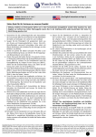
1. Remove the seat, the oil tank/airbox covering and the right front turn signal.
Disconnect the turn signal wire (Image A) and disconnect the negative (-)
battery cable and then the positive (+) battery cable.
2. Remove the right side of the fairing and the air intake tube. Pull the starter
relay along with the rubber holder off of its mount. (Image B) and remove
the cover from the switch box.
3. Mount the relay using the existing nut to the left rear of the relay box. (Image
C) Route the fuse holder rearward to the fuse box and attach the fuse holder to
the frame with a cable tie, such that the fuse holder will be easily accessible.
(Image D) Route the red wire to the positive (+) terminal of the battery but
don’t connect it quite yet.
4. Note how the wires are connected to the switch and then disconnect the
wires from the switch. Route the black wire as well as the two double wires
from the harness towards the front, away from the switch box. (Image E)
Route the three brown wires towards the rear to the negative (-) side of the
battery but don’t connect them quite yet. Reinstall the switch box covering
and reposition the starter relay. (Image F)
5. Install the switch in the fairing (Image G) and reconnect the previously
disconnected wires to the switch. If desired, other options exist as an
alternative to the supplied switch. See your BMW dealer for ideas and
suggestions specific to your bike.
6. Route the three cables towards the front from the switch box along with the
existing cables behind the headlight covering and secure with cable ties.
(Image H)
7. Pull the parking light out of its socket in the headlight. Remove about 2”
of tape from the wires and connect the brown wire from the switch to the
brown wire of the parking light and connect the blue wire from the switch to
the gray/black wire of the parking light using the supplied wire connectors.
(Image I) Reinstall the parking light into the socket in the headlight.
8. Route the double wires to the position where the auxiliary lamps will be
installed and secure the wires, together with the switch wire, with cable ties.
Reinstall the air intake tube, fairing panels and the right turn signal and
covering in reverse order of disassembly carried out in step 1.
9. Remove the left front turn signal along with the covering piece and disconnect
the turn signal wire.
10. Remove the outer screw of the micro lights and attach the to the respective
brackets using a 5X10mm bolt, washer and nut on the top and with the original
mounting bolt minus the rubber washer on the side. (Image J)
11. Remove the turn signal lenses and unplug the wires from the turn signal
reflectors. Pull the wires out of the turn signal stalks. Unscrew and remove
the turn signal stalks.
12. Mount the micro lights, attached to their respective holders to the motorcycle.
Place bushings between the holders and the rear mounts and reinstall the turn
signal stalks, using the original bolts. (Image K) The turn signal wires can now
be fed through the stalks and reattached and the turn signals reassembled.
13. Trim the two-wire light wires to an appropriate length and then crimp a flat
wire connector on the brown wire and a round connector with an insulation
sleeve on the blue wire. (Image L) Place a piece of shrink tubing over both
light wires. Conncet the lamp wires to the harness and reconnect the turn
signal wires.
14. Mount the covering pieces, along with the lights and holding brackets using
5X35mm bolts and washers ate the rear mounting position (Image M) and
straighten out the positioning of the lights.
15. Attach all of the wires to suitable points with cable ties. When doing so, attach
all of the wires to the motorcycle in a clean and orderly fashion and make sure
that the wires are not pinched, interfere with the steering or are vulnerable to
abrasion. Now reconnect the battery leads along with the previously routed
auxiliary light wires by first connecting the positive (+) terminal and then the
negative (-) terminal. Double check your work and reinstall the tank covering
and seat.
1. Demontieren Sie die Sitzbank, die Tankabdeckung und den vorderen rechten
Blinker mit Blende. Ziehen Sie den Blinkerstecker ab (Bild A) und klemmen
Sie die Batterie ab. (Achten Sie darauf das zuerst der Minuspol an der Batterie
abgeklemmt wird, um einen Kurzschluß zu vermeiden)
2. Demontieren Sie die rechte Seite der Verkleidung sowie das Ansaugrohr, ziehen Sie
das Anlasserrelais mit Gummihalter ab (Bild B) und entfernen Sie die Abdeckung
vom Schaltkasten.
3. Montieren Sie das Relais mit der vorhandenen Mutter hinten links im
Schaltkasten (Bild C), verlegen Sie den Sicherungshalter nach hinten zum
Fahrzeugsicherungskasten und befestigen Sie den Sicherungshalter mit einem
Kabelbinder am Rahmen, so das er gut zu erreichen ist (Bild D). Verlegen Sie
das rote Kabel mit Anschlußöse vom Sicherungshalter zum Pluspol der Batterie
(noch nicht anschließen).
4. Markieren Sie die Steckerbelegung am Schalter, ziehen Sie die Stecker ab und
führen Sie das schwarze Kabel sowie die beiden 2adrigen Kabel vorne aus dem
Schaltkasten (Bild E). Verlegen Sie die 3 braunen Kabel hinten rechts aus dem
Schaltkasten zum Minuspol der Batterie (noch nicht anschließen), montieren Sie
nun die Schaltkastenabdeckung und das Anlasserrelais wieder (Bild F).
5. Bauen Sie nun den Schalter in die Verkleidung (Bild G) und stecken Sie die
Stecker in der richtigen Reihenfolge wieder auf den Schalter (bei Fahrzeugen
ohne ABS oder Heizgiffe kann alternatif auch unser Schalter Art.-Nr.:8200095
in die Schalterleiste am Lenker eingebaut werden).
6. Verlegen Sie die drei Kabel vorne aus dem Schaltkasten entlang des vorhandenen
Kabelstrangs hinter die Lampenverkleidung und befestigen Sie diese mit
Kabelbindern (Bild H).
7. Ziehen Sie die Standlichtfassung aus dem Scheinwerfer, entfernen Sie ca. 5
cm vom Isolierband der Standlichtleitung und schließen Sie das braune Kabel
der 2adrigen Leitung vom Schalter an das braune Kabel der Standlichtleitung,
sowie das blaue Kabel der 2adrigen Leitung vom Schalter an das grau/schwarze
Kabel der Standlichtleitung mit je einer Kabelklemme an (Bild I). Stecken Sie
die Standlichtfassung wieder in den Scheinwerfer. (Wahlweise kann das blaue
Kabel auch an die gelbe Pluszuleitung vom Abblendlicht geklemmt werden, dann
leuchten die Zusatzscheinwerfer nur bei eingeschaltetem Abblendlicht.)
8. Verlegen Sie die 2adrigen Kabel zur Position der Zusatzscheinwerfer, befestigen Sie
diese sowie die Schalterleitungen mit Kabelbindern am Fahrzeug und montieren
Sie Ansaugschnorchel und Seitenverkleidung in umgekehrter Reihenfolge wie bei
der Demontage am Fahrzeug.
9. Demontieren Sie den vorderen linken Blinker mit Blende und ziehen Sie den
Blinkerstecker ab.
10. Entfernen Sie die äussere Schraube am Zusatzscheinwerfer, befestigen Sie den
Scheinwerfer oben (mit einer Schraube M5x10, U-Scheiben und Mutter) und
seitlich (mit der Scheinwerferschraube ohne Gummiring) am Halter (Bild J).
11. Demontieren Sie das Blinkerglas, ziehen Sie die Stecker am Blinkerreflektor ab,
ziehen Sie das Blinkerkabel nach hinten aus dem Blinkergehäuse herraus und
schrauben Sie den Blinker von der Blende ab.
12. Montieren Sie den Lampenhalter nun (mit Hülse zwischen Halter und hinterer
Befestigung) zwischen Blende und Blinker mit Original-Blinkerschraube und
Mutter (Bild K). Den Blinker nun wieder in umgekehrter Reihenfolge wie bei der
Demontage zusammenbauen.
13. Längen Sie die 2-adrige Scheinwerferzuleitung passend ab und montieren
Sie auf das braune Kabel eine Flachsteckhülse und auf das blaue Kabel eine
Rundsteckhülse mit Isoliertülle (Bild L). Schieben Sie nun auf die beiden Kabel
vom Scheinwerfer ein passendes Stück Schrumpfschlauch auf, schließen Sie die
Scheinwerferkabel an und stecken Sie den Blinkerstecker wieder ein.
14. Montieren Sie die Blende mit Blinker und Scheinwerfer (an hinterem
Befestigungspunkt mit Schraube M5x35 und U-Scheibe) wieder am Fahrzeug und
richten Sie den Scheinwerfer aus (Bild M).
15. Befestigen Sie alle Kabel und Leitungen mit Kabelbindern am Fahrzeug.
Überprüfen Sie das keine Leitungen beim Einlenken scheuern, gequetscht
werden oder zu stramm sind. Nun können Sie die Plus- und Minusleitung der
Scheinwerferverkabelung mit den Plus- und Minusleitungen vom Fahrzeug
wieder an der Batterie anklemmen, (Achten Sie darauf das zuerst der Pluspol
an der Batterie angeklemmt wird, um einen Kurzschluß zu vermeiden.) sowie
Tankabdeckung und Sitzbank wieder montieren.
Genereller Hinweis: Unsere Anleitungen sind nach bestem Wissen erstellt worden,
erfolgen jedoch ohne Gewähr. Sollten Sie mit dem Anbau nicht zurecht kommen
oder Zweifel haben, so wenden Sie sich bitte an Ihren BMW-Händler oder die
Werkstatt Ihres Vertrauens. Bitte beachten Sie , dass wir keine Gewährleistungen
für fahrzeugspezifische Toleranzen übernehmen können! Es kann im Einzelfall
notwendig sein, dass Produkte diesen angepasst werden müssen.
Copyright
by
Wunderlich
General note: Our fittings instructions are written to the best of our knowledge
but specifications or details may change. If you have difficulties or have doubts
with fitting this part please seek advice from your BMW dealer or workshop of
your choice. Please note that in some cases due to vehicle related tolerances
beyond our control some products might need adjusting to fit. We cannot
warranty parts fitting in those circumstances.
News, Downloads und Informationen
The latest catalogue sections and news
www.wunderlich.de
www.wunderlich.de/update
Anbauhilfe
User Manual
Artikel: Zusatzscheinwerfer F650 GS + Dakar
Bestellnummer: 8600520
Part: Additional Lights F 650 GS + Dakar
Part number: 8600520
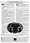
A
B
C
D
E
F
G
H
I
J
K
L
M
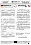
Allgemeine Anzugsdaten
Diese Tabelle spezifiziert Anzugsmomente für normale Befestigungselemente
mit normalen I.S.O.-Gewindenormen. Diese Anzugsmomente gelten nur, wenn
in der Anleitung keine anderen Angaben gemacht wurden. Wenn Teile mit mehreren Befestigungselementen festgezogen werden, die Schrauben und Muttern
kreuzweise und in mehreren Schritten bis zum vorgeschriebenen Anzugsmoment
festziehen, so dass keine Teile verzogen werden. Falls nicht anders vermerkt,
so gelten die Anzugsmomente für trockene und saubere Gewinde. Die anzuziehenden Bauteile sollten dabei Raumtemperatur aufweisen.
Common Torque Values.:
Schraube
Bolt
Allgemeine
Anzugsmomente
Torque Values
M6 mm
6 Nm
4.5 ft-lb
M8 mm
15 Nm
11 ft-lb
M10 mm
30 Nm
22 ft-lb
M12 mm
55 Nm
40,5 ft-lb
This table specifies tightening torques of common fasteners with standard
I.S.O. threads. These torque specifications are only valid when different
torque values are not specified by the manufacturer. When joining parts with several fasteners, evenly tighten in a cross
pattern, in several stages up to the maximum, so that the parts are joined evenly. Unless otherwise specified by the manufacturer, these torque values are for dry and clean bolts and threads, with all components at room temperature.
Schraubenlineal:
Das Lineal soll Ihnen bei der Identifizierung der Schrauben helfen.
Bitte bedenken Sie, daß Schrauben an Ihrer Einschraubtiefe gemessen
werden, also ohne Kopf. M5x25 = Durchmesser 5mm, Länge 25 mm
Metric Ruler for determining bolt sizes:
When measuring bolts, only measure the length of thread
and shaft without the bolt head. For example, M5x12
means diameter of bolt is 5 mm, length 12 mm.