1
Disassemble Keypad
English
Installation Instructions
The PK55XX\RFK55XX keypads can be used on security systems with
up to 64 zones. These keypads are compatible with the latest version
of the folllowing DSC security systems:
•PC580
•PC585
•PC1555MX •PC1565
•PC1616
•PC1832
•PC1864
•PC5005
•PC5008
•PC5010
•PC5015
•PC5016
•PC5020
The RFK55XX keypads combine a wireless receiver with the respective
PK55XX keypad.
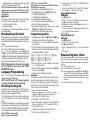
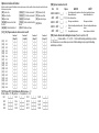
1. Insert a flat head screwdriver into the provided slot (first of two)
2. Move screwdriver toward the back plastic and lift as in the below diagram. This will unhook one side of the front plastic.
3. Repeat step # 1 and 2 on the second provided slot to disconnect the
front plastic and allow access for wiring.
Mounting
You should mount the keypad where it is accessible to designated
points of entry and exit. Once you have selected a dry and secure location, perform the following steps to mount the keypad.
Swing
to engage
4.
Tamper
3
Press to Snap
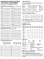
1. Secure Keypad to wall using mounting holes. Use all 4 screws provided
unless mounting on a single gang box.
2. Place keypad into hooks on the backplate and swing down to engage.
3. Run wire through wiring slot or knockouts. Connect Keybus and PGM/Zone
wiring to keypad. Place tamper switch into tamper hole on backplate.
4. Remove keypad from hooks. Place keypad into backplate, ensure the wire
is pushed back into the wall as much as possible. Route the wire inside the
keypad ensuring high components are avoided. Snap the front assembly
closed, ensuring that there is no pressure to the keypad from the wire
below.
1
2
Mount and Wire Keypad
Knock Out
Wiring Slot
Knock Out
Knock Out
Unpacking
The Power keypad package includes the following parts:
•One Power keypad
•Keypad inner door labels
•Four mounting screws
•1 tamper switch
•2 end-of-line resistors
•Installation Instructions
Hooks
3.
Specifications
• Temperature range: -10°C to +55°C (14°F to 131°F), Temperature
range for UL/ULC: 0°C to +49°C (32°F to 120°F)
• Humidity (MAX): 93%R.H.
• Plastic enclosure protection degree: IP30, IK04
• Voltage rating: 12VDC nominal
• Connects to control panel via 4-wire Keybus
• 1 keypad zone input/PGM output*
• PK55XX Current draw: 50mA (standby)/125mA (maximum)
• RFK55XX Current draw: 75mA (standby)/135mA (maximum)
• Wall mount tamper
• 5 programmable function keys
• Ready (Green LED), Armed (Red LED), Trouble (Yellow LED), AC
(Green LED)
• Low temperature sensor
• Frequency: 433.92MHz (RFK55XX-433)
• Up to 32 wireless zones (RFK5500 Only)
• Up to 64 wireless zones (RFK5564 and Power v4.6+Only)
*Zone not to be programmed as Fire type or 24h type.
2.
1.
Tamper
Hooks
NOTE: If any tension found between the front keypad assembly and wiring,
please open the keypad reroute the wire and close again. Repeat these
steps until the keypad is closed properly.
Wiring
1. Before wiring the unit, ensure that all
PK55XX/RFK55XX
power (AC transformer and battery) is disRED
connected from the control panel.
BLK
2. Connect the four Keybus wires from the conYEL
trol panel (red, black, yellow and green) to
GRN
the keypad terminals. Refer to diagram:
To zone or
3. If programmed as an input, you can con- PGM output
nect a device - such as a door contact - to
the ‘P/Z’ terminal of the keypad. This eliminates the need to run wires
back to the control panel for the device. To connect the zone, run one wire
from the device to the ‘P/Z’ terminal and the other wire from the device to
the B (black) terminal. For powered devices, run the red wire to the R
(positive) terminal and the black wire to the B (negative) terminal. When
using end of line supervision, connect the zone according to one of the
configurations outlined in your system’s Installation Manual.
4. If the ‘P/Z’ terminal is programmed as an output, the output follows the
PGM programmed in Section [080]. A small relay, buzzer or other DC