1
Digital Security Controls
Publications Cover Sheet
Part Number: 29007510R001
Revision: 001
Release Number: 7402
Notes: FOR MARKETING FIELD TRIALS ONLY
T
F
A
Description: PC9155 V1.0 INSTALLATION MANUAL
ENGLISH
Type: 33-32 11 x 17 White (Paper)
Pieces: 21
R
D
Printing Instructions: Master Size: 8.5 X 11
Number of Sheets in Master: 84
2 - Sided Printing
Cover Printing Not Required
Finishing: Signature Booklet
Note: Booklets more than 10 sheets
must be trimmed.
PC9155 2-Way Wireless Alarm System V1.0
Installation Guide
Models:
PC9155-433/868
PC9155G-433/868
PC9155D-433/868
Used with:
WT5500-433/868
WT5500P-433/868
Series 2-way Wireless Keypad
TELEPERMIT
These DSC Security Alarm
Systems may be connected
to the Telecom Network
PTC 211 / 09 /017
PTC 211 / 09 /018
PTC 211 / 09 /019
PC9155-433
PC9155D-433
PC9155G-433
RN = 0.5
DG009032
R
D
T
F
A
N11427
IMPORTANT: This manual contains information on limitations regarding product use and function and information
on the limitations as to liability of the manufacturer. The entire manual should be carefully read.
SAFETY INSTRUCTIONS FOR SERVICE PERSONNEL
WARNING: WHEN USING EQUIPMENT CONNECTED TO THE TELEPHONE NETWORK, THERE ARE BASIC SAFETY
INSTRUCTIONS THAT SHOULD ALWAYS BE FOLLOWED. REFER TO THE SAFETY INSTRUCTIONS PROVIDED WITH THIS
PRODUCT; SAVE THEM FOR FUTURE REFERENCE. INSTRUCT THE END-USER REGARDING THE SAFETY PRECAUTIONS
THAT SHALL BE OBSERVED WHEN OPERATING THIS EQUIPMENT.
Selecting a Suitable Location for the Alarm Controller
Use the following list as a guide to find a suitable place for this equipment:
•
Locate the Control Panel near a telephone socket and a power outlet.
•
Select a place that is free from vibration and shocks.
•
Place the Alarm Controller on a flat, stable surface and follow the Installation Instructions.
Do NOT locate this product where persons will walk on the secondary circuit cable(s).
Do NOT connect the Alarm Controller to electrical outlets on the same circuit as large appliances.
Do NOT select a place that exposes your alarm controller to direct sunlight, excessive heat, moisture, vapors, chemicals or dust.
Do NOT install this Equipment near water. (e.g., Bath Tub, Wash Bowl, Kitchen/Laundry sink, In a wet basement, or near swimming pools, etc.).
Do NOT install this equipment and its accessories in areas where there is a risk of explosion.
Do NOT connect this Alarm Controller to electrical outlets controlled by wall switches or automatic timers.
AVOID sources of radio interference.
AVOID setting up the equipment near heaters, air conditioners, ventilators, and/or refrigerators.
AVOID locating this equipment close too or on top of large metal objects (e.g., metal wall studs).
Safety Precautions Required During Installation
•
•
•
•
T
F
A
NEVER install this equipment and/or telephone wiring during a lightning storm.
NEVER touch uninsulated telephone wires or terminals unless the telephone line has been disconnected at the network interface.
Ensure that cables are positioned so that accidents can not occur. Connected cables must not be subject to excessive mechanical strain.
For Direct Plug-in versions, use the transformer supplied with the device.
WARNING
R
D
THIS EQUIPMENT HAS NO MAINS ON/OFF SWITCH. THE PLUG OF THE DIRECT PLUG-IN POWER SUPPLY IS INTENDED TO
SERVE AS THE DISCONNECTING DEVICE IF THE EQUIPMENT MUST BE QUICKLY DISCONNECTED. IT IS IMPERATIVE
THAT ACCESS TO THE MAINS PLUG AND ASSOCIATED MAINS SOCKET/OUTLET, IS NEVER OBSTRUCTED.
IMPORTANT NOTE!
The PC9155 Alarm System shall be installed and used within an
environment that provides the pollution degree max 2 and overvoltages category II NON-HAZARDOUS LOCATIONS, indoor only.
The equipment is DIRECT PLUG-IN (external transformer) or PERMANENTLY CONNECTED (See Figure 2-4: Mounting & Wiring
Details) and is designed to be installed, serviced and/or repaired by
service persons only; [service person is defined as a person having
the appropriate technical training and experience necessary to be
aware of hazards to which that person may be exposed in
performing a task and of measures to minimize the risks to that
person or other persons]. There are no parts replaceable by the
end-user within this equipment. The wiring (cables) used for
installation of the Alarm System and accessories, shall be insulated
with PVC, TFE, PTFE, FEP, Neoprene or Polyamide.
(a) The equipment enclosure must be secured to the building
structure before operation.
(b) Internal wiring must be routed in a manner that prevents:
- Excessive strain or loosening of wire on terminal connections;
- Damage of conductor insulation
(c) Disposal of used batteries shall be made in accordance with
local waste recovery and recycling regulations.
(d) Before servicing, DISCONNECT the power and telephone
connection.
(e) Do NOT route any wiring over circuit boards.
(f) It is the installer’s responsibility to ensure that a readily accessible disconnect device is incorporated in the building for permanently
connected installations.
The Power Supply must be Class II, FAIL SAFE with double or reinforced insulation between the PRIMARY and SECONDARY circuit/ENCLOSURE and be an approved type acceptable to the local authorities. All national wiring rules shall be observed.
Guidelines for Locating Smoke & CO Detectors
The following information is for general guidance only and it is recommended that local fire codes and regulations be consulted when locating and
installing smoke alarms and CO Alarms.
Smoke Detectors
Research indicates that all hostile fires in homes generate smoke to a greater or lesser extent. Detectable quantities of smoke precede detectable levels of
heat in most cases. Smoke alarms should be installed outside of each sleeping area and on each storey of the home.
DSC recommends that additional smoke alarms beyond those required for minimum protection be installed. Additional areas that should be protected include: the basement; bedrooms, especially where smokers sleep; dining rooms; furnace and utility rooms; and any hallways not protected by the required
units.
On smooth ceilings, detectors may be spaced 9.1m (30 feet) apart as a guide. Other spacing may be required depending on ceiling height, air movement,
the presence of joists, uninsulated ceilings, etc. Consult National Fire Alarm Code NFPA 72, CAN/ULC-S553-M86 or other appropriate national standards
for installation recommendations.
• Do not locate smoke detectors at the top of peaked or gabled ceilings; dead air space in these locations may prevent smoke detection.
• Avoid areas with turbulent air flow, such as near doors, fans or windows. Rapid air movement around the detector may prevent smoke from entering the
unit.
• Do not locate detectors in areas of high humidity.
• Do not locate detectors in areas where the temperature rises above 38oC (100oF) or falls below 5oC (41oF).
• Smoke detectors should always be installed in accordance with NFPA 72, the National Fire Alarm Code. Smoke detectors should always be located in accordance with:
‘Smoke detectors shall be installed outside of each separate sleeping area in the immediate vicinity of the bedrooms and on each additional storey of the
family living unit, including basements and excluding crawl spaces and unfinished attics. In new construction, a smoke detector also shall be installed in
each sleeping room’.’Split level arrangement: Smoke detectors are required where shown. Smoke detectors are optional where a door is not provided
between living room and recreation room
R
D
T
F
A
CO Detectors
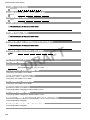
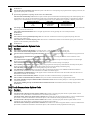
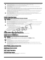
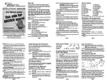
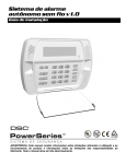
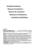
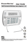
CO gas moves freely in the air. Suggested locations are in or as near as possible to sleeping areas of the home. The
human body is most vulnerable to the effects of CO gas during sleeping hours. For maximum protection, a CO alarm
should be located outside primary sleeping areas or on each level of your home. Figure 3 indicates the suggested
locations in the home. The electronic sensor detects carbon monoxide, measures the concentration and sounds a
loud alarm before a potentially harmful level is reached.
Do NOT place the CO alarm in the following areas:
• Where the temperature may drop below -10ºC or exceed 40 ºC.
• Near paint thinner fumes
• Within 5 feet (1.5 meter) of open flame appliances such as furnaces, stoves and fireplaces
• In exhaust streams from gas engines, vents, flues or chimneys
• Do not place in close proximity to an automobile exhaust pipe; this will damage the detector
BEDROOM
BEDROOM
BEDROOM
GROUND
FLOOR
KITCHEN
GARAGE
BASEMENT
CARBON MONOXIDE DETECTOR
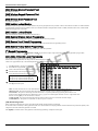
Table of Contents
Chapter
Description
Page
1.
Introduction . . . . . . . . . . . . . . . . . . . . . . . . . . . . . . . . . . . . . . . . . . . . . . . . . . . . . . . . . . .1-1
2.
Installation . . . . . . . . . . . . . . . . . . . . . . . . . . . . . . . . . . . . . . . . . . . . . . . . . . . . . . . . . . . .2-1
3.
Operation . . . . . . . . . . . . . . . . . . . . . . . . . . . . . . . . . . . . . . . . . . . . . . . . . . . . . . . . . . . . .3-1
4.
Programming . . . . . . . . . . . . . . . . . . . . . . . . . . . . . . . . . . . . . . . . . . . . . . . . . . . . . . . . . .4-1
5.
Installer Programming . . . . . . . . . . . . . . . . . . . . . . . . . . . . . . . . . . . . . . . . . . . . . . . . . . .5-1
6.
Testing & Troubleshooting . . . . . . . . . . . . . . . . . . . . . . . . . . . . . . . . . . . . . . . . . . . . . . . .6-1
1.1
1.2
1.3
1.4
2.1
2.2
2.3
2.4
2.5
3.1
3.2
3.3
4.1
4.2
4.3
5.1
5.2
5.3
6.1
6.2
6.3
6.4
6.5
PC9155 Model Differences . . . . . . . . . . . . . . . . . . . . . . . . . . . . . . . . . . . . . . . . . . . . . . . . . . . 1-1
Specifications . . . . . . . . . . . . . . . . . . . . . . . . . . . . . . . . . . . . . . . . . . . . . . . . . . . . . . . . . . . . . . 1-1
Controls & Indicators . . . . . . . . . . . . . . . . . . . . . . . . . . . . . . . . . . . . . . . . . . . . . . . . . . . . . . . . 1-2
Data Entry . . . . . . . . . . . . . . . . . . . . . . . . . . . . . . . . . . . . . . . . . . . . . . . . . . . . . . . . . . . . . . . . 1-2
Hardware Installation . . . . . . . . . . . . . . . . . . . . . . . . . . . . . . . . . . . . . . . . . . . . . . . . . . . . . . . . 2-1
Wiring . . . . . . . . . . . . . . . . . . . . . . . . . . . . . . . . . . . . . . . . . . . . . . . . . . . . . . . . . . . . . . . . . . . . 2-3
Wireless Device Enrollment . . . . . . . . . . . . . . . . . . . . . . . . . . . . . . . . . . . . . . . . . . . . . . . . . . . 2-4
Global Wireless Device Placement Test . . . . . . . . . . . . . . . . . . . . . . . . . . . . . . . . . . . . . . . . . 2-7
GPRS/Ethernet Initialization. . . . . . . . . . . . . . . . . . . . . . . . . . . . . . . . . . . . . . . . . . . . . . . . . . . 2-7
Operating Modes . . . . . . . . . . . . . . . . . . . . . . . . . . . . . . . . . . . . . . . . . . . . . . . . . . . . . . . . . . . 3-1
Language Selection . . . . . . . . . . . . . . . . . . . . . . . . . . . . . . . . . . . . . . . . . . . . . . . . . . . . . . . . . 3-1
[4] Commands . . . . . . . . . . . . . . . . . . . . . . . . . . . . . . . . . . . . . . . . . . . . . . . . . . . . . . . . . . . . . 3-1
Template Programming . . . . . . . . . . . . . . . . . . . . . . . . . . . . . . . . . . . . . . . . . . . . . . . . . . . . . . 4-1
DLS Programming . . . . . . . . . . . . . . . . . . . . . . . . . . . . . . . . . . . . . . . . . . . . . . . . . . . . . . . . . . 4-4
Installer Programming . . . . . . . . . . . . . . . . . . . . . . . . . . . . . . . . . . . . . . . . . . . . . . . . . . . . . . . 4-4
T
F
A
Index to Programming Options . . . . . . . . . . . . . . . . . . . . . . . . . . . . . . . . . . . . . . . . . . . . . . . . 5-1
Programming Worksheets . . . . . . . . . . . . . . . . . . . . . . . . . . . . . . . . . . . . . . . . . . . . . . . . . . . . 5-2
Programming Descriptions. . . . . . . . . . . . . . . . . . . . . . . . . . . . . . . . . . . . . . . . . . . . . . . . . . . 5-24
Appendix A:
Appendix B:
Appendix C:
R
D
Wireless Device Placement Test . . . . . . . . . . . . . . . . . . . . . . . . . . . . . . . . . . . . . . . . . . . . . . . 6-1
Testing the System . . . . . . . . . . . . . . . . . . . . . . . . . . . . . . . . . . . . . . . . . . . . . . . . . . . . . . . . 6-1
Resetting the System to Factory Defaults . . . . . . . . . . . . . . . . . . . . . . . . . . . . . . . . . . . . . . . . 6-2
Troubleshooting . . . . . . . . . . . . . . . . . . . . . . . . . . . . . . . . . . . . . . . . . . . . . . . . . . . . . . . . . . . . 6-3
Battery Removal/Replacement . . . . . . . . . . . . . . . . . . . . . . . . . . . . . . . . . . . . . . . . . . . . . . . . 6-5
Reporting Code Formats . . . . . . . . . . . . . . . . . . . . . . . . . . . . . . . . . . . . . . . . . . . . . . . . . . APP-1
Communicator Format Options . . . . . . . . . . . . . . . . . . . . . . . . . . . . . . . . . . . . . . . . . . . . . APP-3
Regulatory Approvals Information . . . . . . . . . . . . . . . . . . . . . . . . . . . . . . . . . . . . . . . . . . . APP-5
List of Illustrations
Figure
1-1
2-1
2-2
2-3
Description
Page
Controls & Indicators - Keypad . . . . . . . . . . . . . . . . . . . . . . . . . . . . . . . . . . . . . . . . . . . . . . . . 1-2
AC Fuse Block . . . . . . . . . . . . . . . . . . . . . . . . . . . . . . . . . . . . . . . . . . . . . . . . . . . . . . . . . . . . . 2-1
GPRS/Ethernet Module Wiring Details . . . . . . . . . . . . . . . . . . . . . . . . . . . . . . . . . . . . . . . . . . 2-1
Mounting & Wiring Details . . . . . . . . . . . . . . . . . . . . . . . . . . . . . . . . . . . . . . . . . . . . . . . . . . . . 2-2
List of Tables
Table
1-1
1-2
1-3
1-4
2-1
Description
Page
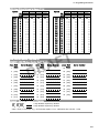
PC9155 Models . . . . . . . . . . . . . . . . . . . . . . . . . . . . . . . . . . . . . . . . . . . . . . . . . . . . . . . . . . . . 1-1
Specifications . . . . . . . . . . . . . . . . . . . . . . . . . . . . . . . . . . . . . . . . . . . . . . . . . . . . . . . . . . . . . . 1-1
Compatible Devices . . . . . . . . . . . . . . . . . . . . . . . . . . . . . . . . . . . . . . . . . . . . . . . . . . . . . . . . . 1-1
Controls & Indicators - Alarm Panel . . . . . . . . . . . . . . . . . . . . . . . . . . . . . . . . . . . . . . . . . . . . . 1-2
Terminal Block Connections . . . . . . . . . . . . . . . . . . . . . . . . . . . . . . . . . . . . . . . . . . . . . . . . . . 2-2
1 Introduction
1 Introduction
This manual provides installation and programming information for the PC9155 two-way wireless series of Alarm Panels. The PC9155 is a twoway wireless alarm system that can interface with one-way and two-way RF devices. Three separate hardware platforms exist for the 433 MHz
and 868 MHz versions.
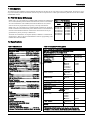
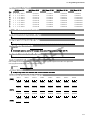
1.1 PC9155 Model Differences
Models with a ‘G’ in the suffix have a GS2065 module installed. The GS2065 module is a GSM (Global System for Mobile communications) wireless cell communicator that communicates with a GPRS (General Packet Radio Services) Global
Network that can be programmed as the primary or back up communicator.
Table 1-1 PC9155 Models
Model
Operating
Frequency
GS2065
TL265GS
Models with a ‘D’ in the suffix have a TL265GS module installed. The TL265GS
module combines the dual functionality of the GS2065 wireless cell communicator
and T-Link TCP/IP Ethernet/Internet communicator. Either function can be programmed as the primary or back up communicator.
PC9155-433
PC9155-868
PC9155G-433
PC9155G-868
PC9155D433
PC9155D868
433.92MHz
868.35MHz
433.92MHz
868.35MHz
433.92MHz
868.35MHz
✖
✖
✔
✔
✖
✖
✖
✖
✖
✖
✔
✔
All models can communicate via telephone (PSTN) in addition to cell and internet
described above. Refer to the associated Installation Guide for programming of the
GS2065 and TL265GS modules.
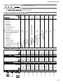
1.2 Specifications
Table 1-2 Specifications
T
F
A
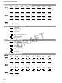
Table 1-3 Compatible Wireless Devices
Specifications
Compatible Wireless Devices
Temperature Range......................0°C-49°C (32°F - 120°F)
Humidity.......................................93%RH Non Condensing
Power Supply.............................. 16.5Vac/20VA @50/60Hz
R
D
Current Draw (panel)
240 VAC Primary .................................... 57mA(AC)(Max)
120 VAC Primary .................................. 114mA(AC)(Max)
16.5 VAC Secondary ............................ 855mA(AC)(Max)
Current Draw (panel) Battery Only
Standby............................................................90mA Max
Transmit (GPRS/Ethernet Module) ................330mA Max
Battery Capacity ............................................. 12VDC 2.3Ah
Charging Rate.................................. 240ma. (12Hrs Max)
Backup Time (No Aux).............................................. 24Hr
Aux+
Voltage.......................................................... 9.6-13.8VDC
Current......................................................... 200 mA Max
PGM 1&2 Output Current .................................. 50mA (ea.)
Wireless Transceiver
Operating Frequency Panel......433.92 MHz/868.35 MHZ
Dimensions:
PC9155....................................... H10.5 x W8.5 x D 2.3 in
WT5500 ..................................... H4.9 x W6.5 x D 1.25 in
with wall bracket ...................... H4.9 x W6.5 x D 1.5 in
Weight
PC9155 NA............................................ 4.1 lb. (1.830Kg)
PC9155 EU (Internal Transformer) ........ 5.1 lb. (2.275Kg)
WT5500 ................................................. 1.0 lb. (0.454Kg)
Out of the Box:
PC9155
RJ31-x Telephone (NA only)
Transformer: NA external, EU internal
Battery (installed)
Mounting Hardware Kit
Installation, Keypad & User manuals ............... Qty (1) ea.
One-way, Two-way Device Installation sheets...as required
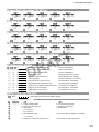
WS, WLS, EV prefixes indicate one-way wireless device.
WT prefix indicates two-way wireless device.
Descriptions
PC9155x-433
PC9155x-868
Wireless Keypads
UL
WT5500-433
ULWT5500P-433
ULPT4
WT5500-868
WT5500P-868
PT8
WS4945
WS4965
**WS4975
EV-DW4917
EV-DW4955
***EV-DW4975
WS8945
WS8965
WS8975
WS4904
WS4904P
ULWLS914-433
WS8904
WS8904P
Proximity Tag
Door Contacts
UL
UL
Motion Detectors
UL
UL
WS4916
WS4926
Smoke Detector
UL
WS8916
UL
CO (Carbon Monoxide) Detector
WS4913
WS8913
Flood Detector
WS4985
WS8985
Glass Break Detectors
UL
WLS912L-433
Shock Detector
Wireless Sirens
EV-DW4927
Indoor
Outdoor
WT4901
WT4911
WT8901
WT8911
Wireless Keys
UL
WS4939
WS4949
WS4959
WS4969
ULWT4989
WS8939
Panic Pendants
UL
UL
UL
WS4938
WS4938-2W
WT8989
WS8938
UL
Hold-up
WLS928-433
Approved for UL installations.
**Not available in North America, South America and New Zealand
***Available in North America, South America and New Zealand only
UL
1-1
PC9155 Wireless Alarm System
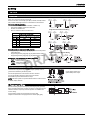
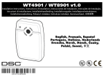
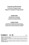
1.1 Controls & Indicators
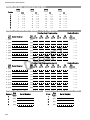
The PC9155 can have a maximum of eight status indicators located on the front panel. The four indicators located on the left side of the panel
indicate the Ready status, Armed status, Trouble status and AC Power Status of the alarm system. The four indicators are located on the right side
of the panel only if a GS2065 or TL265GS module is installed. These indicate Communicator Trouble status, Network status (TL265GS only),
and High or Low signal strength.
Table 1-4 Controls & Indicators - Alarm Panel
Alarm Indicators
GPRS/Ethernet Module Indicators
Ready: Panel is ready to be armed.
Communicator Trouble: Enter [4][2] to view troubles.
Armed: Panel is armed.
Network: Internet communication absent.
Trouble: Enter [4][2] to view troubles.
Signal Strength (High): GPRS signal strength is Good.
AC Power: On=AC present. OFF=AC absent
Signal Strength: (Low): GPRS signal strength is Poor.
Figure 1-1 Controls & Indicators - Keypad
LCD
< > indicates user can
scroll through options
T
F
A
LED Indicators
Scroll Keys
Emergency Keys
Fire
Auxiliary
Panic
Ready
Armed
Trouble
AC Power
System is
Ready to Arm <>
R
D
1
4
7
*
2
3
5
6
8
9
0
#
Function
Keys
DG009033
Ambient Light
Sensor
2.2 Data Entry
Conventions Used
Brackets ‘[ ]’ indicate numbers or symbols that are to be entered on the keypad.
E.g., [4][8][Installer Code][898] requires you to enter
First Entry:
Pressing
,
indicates to the Alarm System that you are about to enter a special command.
Second Entry:
Pressing
indicates to the Alarm System that you are entering installer programming mode.
Third Entry:
Pressing
enters the default installer code; you will be prompted to change this in system programming to
restrict unauthorized access.
Fourth Entry:
This entry indicates the particular programming section you wish to enter.
E.g. [898] Wireless Device Enrollment
[899] Template programming
[999] Alarm System Default
1-2
1 Introduction
Entering Letters:
Some data entries require the entry of letters (i.e., A, B, C, D, E, F).
To enter a letter, press , and its corresponding digit. See the table below.
The cursor will blink to indicate that you are entering letters. To revert back to numeric entry press
1=A
2=B
3=C
, .
4=D
5=E
6=F
Incorrect Data Entries:
To change the current data entry before it has been accepted by the Alarm System, use the scroll keys to reposition the cursor and re-enter the
digit. If the programmed data has already been accepted by the system, press [#] to exit the section and then re-enter the programming section to
begin re-programming of the data.
If you incorrectly enter 0001 in Step 2 of Program Alarm System in Template Programming, you must either reset the Alarm System to its default
values (Sect. [996], re-enroll all wireless devices and re-program the system) or re-enter the correct data in Installer Programming [4][8].
Special Keys:
The scroll symbols < > appearing on the display indicate that there are options that you can view by pressing the
keys can also be used to position the cursor for re-entry of incorrect digits.
keys. These scroll
The , key functions similarly to the ‘ENTER’ key on a personal computer. It is generally used to accept the existing programming option. It
is also the first key entry for [4] Commands. It is also used to enter the letters A-F when in the Installer Programming mode.
The
key functions similarly to the ‘ESCAPE’ key on a personal computer. It is generally used to exit the current programming section or to
return to the previous menu.
R
D
T
F
A
1-3
2 Installation
2 Installation
2.1 Hardware Installation
Hardware Installation
Step
1
Select a suitable location for the alarm panel in a dry location, close to an unswitched AC outlet, phone line (if required), and
ethernet cable (if required). Do NOT mount system on an electrical box. Position system away from metal objects e.g.,
appliances, furnace, duct work etc.
Step
2
Remove the front cover with a slotted screwdriver.
- Gently pry the front cover from the chassis using a small slotted screw driver in the slots provided.
i
R
D
T
F
A
Fuse
250VAC/
160mA
Line
'*
Ethernet communication lines must be connected to an Approved (acceptable to local
authorities) type NID (Network Interface Device) before leaving the premises (e.g., UL
Installations, UL60950 listed NID).
If required Remove/Replace existing coaxial cable and connect TL265GS/GS2065 to
an external antenna.
To Internal Transformer
FUSE
For PC9155 models with an internal transformer, Route AC wiring through the AC wiring
guide then through the access hole adjacent to the internal transformer. Secure AC Line
and Neutral (N) wiring to fused side of the terminal block as indicated.
For PC9155D models, Route the RJ-45 terminated CAT5 Ethernet Cable through the
wiring guide then through the wiring access hole and connect to the RJ-45 jack located on
the TL265GS module.
Neutral
(N)
AC
Input
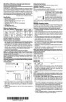
Figure 2-1: AC Fuse Block
Figure 2-2:GPRS/Ethernet Module Wiring Details
Jumpering Ethernet Cable to ground
may cause communication problems.
Use with caution
To Alternate External
Antenna Connection
GND SHLD
To Router/Ethernet
SIM Card
Insert small flat head screwdriver
between cable and Rx/Tx module
then gently pry plug loose.
T-1 R-1 TIP RING IO2 IO1 -AUX AUX+ AC AC
BATTERY CONNECTION (NOT SHOWN)
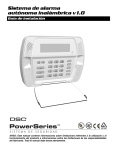
Step
3
• Route wiring through the wiring channels provided to the wiring access hole. See Figure 2-3
• Secure unit to wall using the mounting holes provided
2-1
PC9155 Wireless Alarm System
Figure 2-3: Mounting & Wiring Details
BACK VIEW
FRONT VIEW (COVER REMOVED)
FUSE
3&/,1.
DG009034
5('
R
D
T
F
A
To internal
transformer
Ethernet
Connection
I/O
Wiring
Phone
Line IN/OUT
T-1 R-1 TIP RING I/O2 I/O1
- AUX + AC AC
To AC
terminals
CAUTION: The Ethernet communication lines must be connected first to an Approved (acceptable to the local authorities) type
NID (Network Interface Device) before leaving the premises (e.g., UL installations, UL60950 Listed NID).
Table 2-1 Terminal Block Connections
Phone Line
T1-Brn
Connects to in-house phone line
R1- Gra
Connects to in-house phone line
Tip - Grn
Connects to outside phone Line. Allows system to
seize the phone line from devices connected to T1-R1
PC9155
Telephone
T-1 R-1 Tip Ring
2
I/O
1
Aux
AC
Ring - Red
Connects to outside phone Line. Allows system to seize the phone line from devices connected to T1-R1
I/O
I/O - 1
Can be configured as a PGM output (50mA) or hard wired zone input (Zone 33)
I/O - 2
Can be configured as a PGM output (50mA) or hard wired zone input (Zone 34)
Aux
Aux -
Provides ground connection for hard wired zones and Aux+ power.
Aux +
Provides +12VDC, 200mA (Max.) for PGMs and modules.
AC
~
Connects directly to external 16.5VAC transformer or fused internal transformer
~
Connects directly to external 16.5VAC transformer or fused internal transformer
2-2
2 Installation
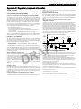
2.2 Wiring:
1. I/O Wiring:
The two I/O terminals can be programmed as hard wired zone inputs and/or PGM outputs. See programming Section [013] Opt [1,2].
1a. Zone Wiring:
Zones 1 - 32 are reserved for wireless zones. If programmed as zone
inputs, I/O-1 is zone 33 and I/O-2 is zone 34.
Zones can be wired for Normally Open (NO) contacts, Normally Closed
(NC) contacts with Single-end-of-line or Double-end-of-line resistors.
Observe the following guidelines.
•
For UL/ULC listed installations use SEOL or DEOL only.
•
Use minimim 22AWG, maximum 18 AWG wire
•
Do NOT use shielded wire
•
Wire run resistance shall not exceed 100 Ω
Wire Size
ANY I/O
TERMINAL
AUX TERMINAL
AUX TERMINAL
Single End-of-Line Resistor Wiring
Burglary Zone Wiring Chart
AWG mm
Normally Closed Loops - Do NOT use for UL Installations
ANY I/O
TERMINAL
ANY I/O
TERMINAL
AUX TERMINAL
ANY I/O
TERMINAL
AUX TERMINAL
ANY I/O
TERMINAL
AUX TERMINAL
Max wire length to End-of-line resistor
Feet
Meters
22
0.65
3000
914
20
19
0.81
0.91
4900
6200
1493
1889
18
1.02
7800
2377
Figures are based on maximum wiring resistance of 100 Ω
T
F
A
Zones 33 and 34 are defaulted for SEOL resistors
•
Programming Section [133]/[134] opt.[14] Selects Normally Closed
or Normally Open
•
Programming Section [133]/[134] opt.[15] Selects SEOL resistors
•
Programming Section [133]/[134] opt.[16] Selects DEOL resistors
R
D
Zone Status - Loop Resistance/Loop Status (DEOL only)
•
Fault - 0Ω (shorted wire/loop)
•
Secure - 5,600Ω (contact closed)
•
Tamper - infinite (broken wire, open)
•
Violated - 11,200Ω (contact open)
1b. Programmable Output (PGM) and Aux Wiring:
ANY I/O
TERMINAL
AUX TERMINAL
Double End-of-Line Resistor Wiring
ANY I/O
TERMINAL
AUX TERMINAL
ANY I/O
TERMINAL
AUX TERMINAL
LED output with:
I/O terminals configured as Programmable Outputs (PGMs) switch to
ground when activated by the alarm system.
Connect the positive side of the device to the Aux+ terminal.
I/O
I/O
Current limiting resistor and
optional Relay driver output
Connect the negative side of the device to the I/O terminal.
Each PGM can provide 50mA maximum output.
NOTE: The alarm system can provide 200mA maximum of AUX current
for PGMs, relays, LEDs etc.
2. Telephone Line Wiring:
Wire the incoming line (Phone Company) and Outgoing line (premises)
to the connection terminals to an RJ31x connector as indicated. This will
allow line seizure if required by the Alarm System. Use 24AWG minimum for wiring.
Communication formats are programmed in section [350].
Telephone Call Directions are programmed in sections [351]-[376].
T-1
R-1
TIP
RING
BRN
GRA
GRN
RED
RJ-31X
2-3
PC9155 Wireless Alarm System
3. Battery
4. AC Wiring
Sealed Lead Acid Battery
Model FP 1223 ...................... 12VDC 2.3Ah@20Hr. discharge rate
Standby....................................................................................24Hr
Battery Replacement.
Removal:
(1) Disconnect the RED (+) and BLACK (-) connectors from the battery
(2) Depress the plastic battery retainer on the right side of the battery
with thumb to free battery from the housing, then remove battery.
AC Transformer Requirements:
Primary: 120VAC, 50/60Hz., 0.33A
240VAC, 50/60Hz.,0.100A
(Fuse: 503 Si, 250V/160mA Fast-Blo)
Secondary: 16.5VAC/20VA
Replacement:
Insert Left side of Battery (Plus (+) terminal)
(1) Remove terminal protection from battery.
(2) Install Battery cable on Battery spade lug terminals.
(3) Slide left side of battery under the left battery retaining bracket.
(4) Insert a flat head screwdriver between the battery and left retaining
bracket. Lever the left retaining bracket to the right while pressing the
battery firmly in place.
(5) If required route battery cable through wire guides and connect to the
battery connector.
The following Plug-in Transformers shall be used:
North America (UL Listed Installations)
PTD1620U-CC
Canada (ULC Listed Installations)
PTD1620
Internal Transformer
Secondary Wire Run Distance
AWG
Feet
Meters
24
22
20
18
5.8
9.3
14.8
23.5
1.8
2.8
4.5
7.2
• DSC recommends replacement every 3-5 years.
• Dispose of battery in accordance with local regulations.
Do NOT connect transformer to a receptacle controlled by a switch. Use a Class 2, power limited transformer for UL/ULC installations
2.3 Wireless Device Enrollment
T
F
A
Installing a one-way or two-way wireless device on the system requires programming the system with the Electronic Serial Number (ESN) so that
it can be identified when an event is communicated. Two-way devices must also initiate communication with the control panel to complete the
enrollment process. The control panel will then assign the device a unique system ID, device ID and encryption key. This information is sent to
the device and is stored in its memory. The system uses these ID's and encryption to communicate events.
Methods of Enrollment:
R
D
There are two methods of enrollment:
•
Quick Enroll – Used to enroll new devices on the system. (See below for procedure). The Quick Enroll procedure performs the two-way
enrolment communications in the back ground. The Two-way device and One-way device enrollment procedures are identical.
•
Manual or DLS Enroll – See Installer programming or DLS Programming (Section [804]). Manual or DLS enrollment of two-way wireless
keys requires the physical triggering of the device to complete the enrollment.
Enroll wireless devices in the following sequence.
•
Keypad
•
Sounders
•
Sensors
•
Pendants
•
Wireless Keys (Key Fobs)
Refer to the associated Installation Sheet for additional details on how to activate specific wireless devices.
2-4
2 Installation
Enrolling Wireless Keypads
When the PC9155 is first powered up a 2 minute window is established for enrolling the first keypad. The AC Power and Ready
LEDs will flash for the duration of the enrollment window. The keypad must be powered up and enrolled within this period. If the
keypad is not enrolled during this window (i.e. The AC Power and Ready LEDs stop flashing) the Keypad and Panel must be
powered down then powered up again to reopen the 2 minute enrollment window.
Step
1
Power up Alarm System.
- Connect Alarm System to AC Power
- The Ready and AC LEDs will flash for 2 minutes
Step
2
Power up Keypad.
- Connect Keypad to AC Power or install new batteries
- After a few seconds the keypad may beep rapidly
- ‘Hold [1] and [4] to Enroll Keypad’ will be displayed
Press the , and
keys simultaneously to enroll keypad
‘WFKP Enrollment Successful’ will be displayed
i
Hold [1] and [*]
to Enroll Keypad
WFKP Enrollment
Successful
If the “Failed to Enroll” message is displayed perform the following:
• Retry The Enrollment
• Reposition the keypad closer to the control panel
• Verify that the READY and POWER LED indicators are flashing on the panel
• Check for RF interference
• Verify that the keypad is the correct model for the PC9155 System
R
D
T
F
A
Enrolling Additional Keypads, Sirens & Key Fobs
Step
1
Enter [4][8][5555][898]
The following will be displayed:
Step
2
Activate the device as indicated below or in the associated Installation Sheet.
• Press the , and
keys simultaneously on the additional keypad.
• Tamper the siren, power it up or press the test button to enroll it.
• Press any Key on a key fob
(Press the “2” and “3” buttons simultaneously to re-enroll a two-way key fob)
The Electronic Serial Number (ESN) will be displayed on the first keypad
Press , to confirm the ESN
If the ESN is incorrect press
then repeat this step.
Step
3
After successful confirmation of the ESN you will be prompted to enter the Slot#
- The next available slot will be displayed. Press , to accept or enter 01-04 for
Keypads and Sirens or 01-16 for Key Fobs
Wireless
Enrollment Mode
2-5
PC9155 Wireless Alarm System
Enrolling Sensors & Pendants
Step
1
Enter [*][5555][898]
“Wireless Enrollment Mode” will be displayed
Step
2
Place the Wireless device near the Alarm System.
Activate the device as described in the associated installation sheet.
The Electronic Serial Number (ESN) will be displayed.
Press , to confirm Serial Number
Wireless
Enrollment Mode
223E02
Confirm ESN?
*
The ESN is a 6-digit alphanumeric number located on a removable sticker on the wireless device.
If the Serial Number is incorrect, Press
Step
3
and repeat this step.
After successful confirmation of the Serial Number
You will be prompted to enter the Zone # and the next available zone will be displayed
Press , to accept the selection or enter a zone number (01 to 32)
Enter Zone #
00
For the first enrolled device enter
i
Step
3
Step
4
If you attempt to enroll a second device in a zone that has already been enrolled in
You will be prompted whether to overwrite the existing zone
Press , to overwrite the zone
Press
to re-enter the zone number (previous display)
R
D
T
F
A
After successful entry of the Zone Number you will be prompted to enter the Zone
Type. (The recommended Zone type will be displayed). Press , to accept the
zone type or:
- Enter
for: Delay Type 1 - Entry/Exit Point e.g., Door
- Enter
for: Instant Type - e.g., Window
- Enter
for: Interior Stay/Away Type - e.g., Motion Detector
- Enter
for: Delayed 24 Hr. Fire Type - e.g., Smoke detector
- Enter
for: 24 Hr. Panic - e.g., Panic Pendant
After successful entry of the Zone Type
The Alarm System will return you to the Wireless Enrollment screen
Continue with one of the following:
- Activate another sensor or pendant to continue enrollment (Step 2)
- Press
to Enter System programming
- Press
Zone 01: 224A01
Overwrite?
*
Press (*) for
Zone Type: 03
Wireless
Enrollment Mode
to exit Installer Programming
Enrolling Proximity Tags
If this function is available on the keypad, in the [4][5] menu you have the option to assign a Proximity Tag to an Access Code
once the Access Code has been entered. The keypad will prompt you to swipe the tag to enroll it during User Access Code
assignment.
i
2-6
To unenroll a proximity tag the user code must be deleted. To retain the user code it must be reentered.
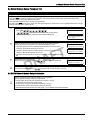
2.4 Global Wireless Device Placement Test
2.4 Global Wireless Device Placement Test
Wireless Device Placement
Perform the Wireless Device Placement testing on keypads, sounders and sensors only.
• This test is NOT required for wireless keys or pendants. Verify that pendants and Key FOBs operate within the desired
Operating area by arming and disarming the sytem.
• Test each device multiple times to ensure a good placement.
• If a device tests BAD reposition the device and retest. Slight changes in placement can cause significant differences in signal
strength and range of the wireless device.
Step
1
• To enter ‘Wireless Device Placement Test.
Press ,
represents the new installer code programmed in
Installer’s programming to replace the 5555 default installer code.
Step
2
Place the wireless device in the location where the device will be mounted.
Activate the device as described in the associated installation sheet.
T
F
A
• If the Alarm System receives a STRONG signal the bell will sound once and
‘Location is Good’ will be displayed on the LCD.
• If the Alarm System receives a WEAK signal the bell will sound 3 times and
‘Location is Bad’ will be displayed on the LCD.
• If the Alarm System indicates no response, reposition wireless device and repeat
test.
Step
3
i
R
D
Repeat Step 2 for Each Device.
When Placement is completed, press
to exit Installer’s Programming.
Enter Section
--Activate Device
For Test
Activate Device
Location is Good
Activate Device
Location is Bad
System is
Ready to Arm
<>
Two-way wireless keys must be activated by pressing any key before they become functional.
To re-enroll a wireless key press
simultaneously for approximately 2 minutes.
2.5 GPRS/Ethernet Module Setup/Initialization
i
Perform the following after system installation and programming.
Ensure that the following sections are programmed:
• Central Station Phone Number,(Template Programming - Entry 5)
(if applicable, in Sections [301]-[303] & [305])
• Account code, Sect [310], (Template Programming - Entry 6)
• Communications Format, Section [350]- Set to [04] SIA FSK
• GPRS/Ethernet Module Enable Sect [382] Opt[5] - Set to GPRS/Ehernet Module Enabled
2-7
3 Operation
3 Operation
3.1 Operating Modes
3.1.1 – Away Arming
Away Arming arms the entire system including the perimeter and interior devices. The Ready light must be ON to arm the system. If the Ready
light is OFF, ensure all protected doors and windows are secure or bypassed. To arm the system in the Away mode, either press and hold the
Away function key for 2 seconds or enter a valid user code and leave the premises through a door programmed as Delay. Upon pressing a function
key or entering an access code, the Armed light will turn ON. If the Audible Exit Delay option is enabled, the keypad will beep once every second
during the exit delay (and three times a second during the last 10 seconds) to alert the user to leave. The Ready light will turn off when the Exit
Delay ends.
3.1.2 – Stay Arming
i
Zones must be programmed with Zone definitions: 05 Interior Stay/Away, 06 Delay Stay/Away, or 32 Instant Stay/
Away for this function to work.
Stay Arming is intended to arm the perimeter of the premises while permitting movement within the premises. The Ready light must be ON to
arm the system. If the Ready light is OFF ensure all protected doors and windows are secure or bypassed. To arm the system in the Stay mode,
either press and hold the Stay function key for 2 seconds or enter a valid user code and stay within the premises (do NOT violate a door programmed as Delay). Upon pressing a function key or entering an access code, the Armed light will turn ON. If the Stay function button is used,
the keypad will not beep during the exit delay and the user can still exit the building without the arming reverting to Away Mode. If a user code is
used, the keypad will beep if the Audible Exit Delay option is enabled. The Ready light will turn off when the Exit Delay ends.
3.1.3 – Night Arming
T
F
A
Night Arming is intended to arm the perimeter and restrict movement to designated areas in the interior (e.g., hallways from bedrooms to bathrooms). If night zones are programmed, entering [4][1] while the system is armed in stay mode will re-activate all interior zones except those programmed as night zones. Alternatively, while the system is disarmed the Night Arm function key can be pressed for 2 seconds to arm the panel in
Night mode. The Ready light must be ON (disarmed) or the system must be armed in the Stay Mode to arm the system in this mode. In Night
mode only Night zones (Zone definition 37) are bypassed. When activated, there are no acknowledgement beeps, the exit delay is silent and the
panel logs Armed in Night Mode. If there are no Night zone types programmed on the system, the system will arm in Away mode, and the panel
will log Armed in Away Mode.
3.1.4 – Disarming
R
D
The user must enter through a door programmed as Delay. Upon entering, the keypad will emit a steady entry delay tone (and emit a pulsing tone
during the last 10 seconds of entry delay) to alert the user to disarm the system. To disarm the system, enter a valid user code, present your proximity tag or use your wireless key. If an alarm occurred while the panel was armed, the keypad will display ‘Alarm in Memory’ and the zone(s)
that went into alarm during the armed period. Press the [#] key to return the keypad to the Ready state.
3.2 Language Selection
The keypad can be programmed to display messages and labels in different languages. Perform the following when in ‘Ready to Arm’ mode or
base Installer programming menu:
[1] Press and hold both scroll keys [< >] simultaneously until language options are displayed.
[2] Scroll to the desired language using the scroll keys [< >].
[3] Press [4] to select the desired language.
3.3 ✱ Commands
The following is a list of the [4] commands available and a description of each:
[4][1]
[4][2]
[4][3]
[4[4]
[4][5][Master/Supervisory Code]
[4][6][Master/Supervisory Code]
[4][7][1/2]
[4][8][Installer Code]
[4][9][User Code]
[4][0]
Bypass (disarmed state)/Reactivate Stay/Away Zones (armed state)
Display Trouble Conditions
Display Alarm Memory
Door Chime Enable/Disable
User Code Programming
User Functions
Command Outputs 1 and 2
Installer Programming
No-Entry Arming
Quick Arm (disarmed state)/Quick Exit (armed state)
3-1
PC9155 Wireless Alarm System
[4][1] – Bypass/Re-activate Stay/Away and Night Zones
Press [4][1] to enter the bypass mode. If the Code Required for Bypass option is enabled, enter a valid user code. The keypad will display ‘Scroll
to Bypass Zones’. The keypad will display the programmed zone labels for the zones and include the letter ‘O’ in the bottom, right corner if the
zone is violated or the letter ‘B’ if the zone is bypassed. Scroll to the appropriate zone and press the [4] key to change the bypass status (or enter
the 2-digit zone number). Once the correct zones are bypassed, press [#] to exit.
Additional Bypass Commands:
Bypass Recall:
Clear Bypass:
Save Bypass:
Recall Save:
In Bypass Mode, press [99]. The keypad will recall the last group of zones that were bypassed.
Press [00]. The keypad will clear the bypass on all zones.
Press [95]. The keypad will save which zones are manually bypassed.
Press [91]. The keypad will recall the bypassed zones that were saved.
Re-activate Stay/Away and Night Zones:
Press [4][1] when the system is armed in the Stay mode to change the armed status to Away mode or Night mode. The system will add the Stay/
Away zones back into the system after the exit delay time expires.
i
If any zones are programmed as Night Zones (zone definition 37) pressing [4][1] when the system is in
Stay mode will activate Night mode instead of Away mode. Only Night Zones will be bypassed. The Stay
and Away zones will be added back into the system.
[4][2] – Trouble Display
Refer to Chapter 6: Testing & Troubleshooting, for troubleshooting assistance and a detailed description of all trouble conditions.
[4][3] – Alarm Memory Display
T
F
A
Pressing the scroll <> keys will display an “Alarms in Memory” message if an alarm occurred during the last armed period. Pressing [4][3] will
display the message “Scroll to view Alarms”. To clear the Memory, arm then disarm the system.
[4][4] – Door Chime Enable/Disable
R
D
Press [4][4]. The keypad will emit 3 rapid beeps to indicate that the door chime feature is enabled and a steady 2-second tone if disabled. The
same function can be performed by pressing and holding the Chime function key for 2 seconds.
[4][5] – Program User Codes
The following table identifies available user codes:
Code
Type
[01] – [16]
[40]
General User Codes
Master Code
Programming User Codes:
Function
Determined by attributes programmed below
All Attributes described below
Press [4][5] followed by the Master Code. The keypad will display the first user (user 01) and include the letter ‘P’ if the user code is programmed. Scroll to the appropriate user and press the [4] key to program the user (or enter the 2-digit user number). Enter a new 4 or 6-digit user
code or press [4] to delete the user code. After the user code is programmed or deleted, scroll to another user or press [#] to exit.
i
Proximity tags can be assigned to a programmed user code on WT5500P Keypads. After assigning a User Code,
the display will prompt the installer to swipe the tag. This will assign a proximity tag to the user code. To delete a
Proximity Tag, the User code must be deleted. Refer to the Proximity Tag Installation Sheet for details
Programming User Attributes:
Press [4][5] followed by the Master Code or Supervisor Code. Press [9] followed by the 2-digit user to change to the user attributes.
To change the user attributes, press the number corresponding to the attribute or scroll to the desired attribute and press [4]. When the correct
attributes are assigned to the user, press [#] to exit. To change the user attributes for another user, press [9] followed by the 2-digit user number.
When finished, press [#] to exit.
i
3-2
• These attributes affect the operation of wireless keys.
• Wireless key numbers (01-16) correspond with User access codes (01-16).
• Duress codes are not valid when entering [*][5], [*][6] or [*][8] sections.
• Duplicate codes and codes that are +/- 1 of an existing code can not be programmed.
3 Operation
[1]
Supervisor’s Code: This attribute makes the code valid when entering the [4][5] User Code Programming section and [4][6] User
Functions. Note, these codes can only program codes which have equal or lesser attributes. This attribute will also allow this user to
create bypass groups if an access code is required to enter into [4][1] Bypassing.
[2]
Duress Code: Duress codes are standard user codes that will transmit the Duress Alarm Reporting Code whenever the code is
entered to perform any function on the system.
[3]
Bypass Zones: User can manually bypass zones if bypassing requires an access code.
[4-6]
Future Use
[7]
Bell Squawk On Arming/Disarming: The panel will squawk the bell when the user arms using the away function key and a user
code, or if the away function key is pressed on an identified wireless key.
[8]
One-time Use Code: The One-time-use Code allows unlimited arming but only permits a single disarming once a day. The Disarm
function is restored at midnight.
[4][6] – User Functions
Press [4][6] followed by the Master Code, then press the number corresponding to the following functions or scroll to the desired option, then
press [4].
[1]
[2]-[3]
Program Time and Date: Enter the time and date using the following format [HH:MM] [MM/DD/YY]. Program the time using
military standard (e.g., 8:00 pm = 20:00 hours).
Future Use
T
F
A
[4]
System Test: The system activates the siren output on medium volume for 2 seconds followed by full volume alarm for 2 seconds.
All display lights and LCD pixels will turn on.
[5]
Enable DLS: The panel will temporarily enable DLS double-call for 6 hours.
[6]
User Initiated DLS: The panel will attempt to call the DLS computer.
[7]
Future Use
[8]
User Walk Test Mode: Walk Test mode allows you to test the operation of each detector in the system. Press [*][6][Master
Code][8] to initiate the Walk Test Mode. While in Walk Test mode, the Ready, Armed, and Trouble LED's will flash to indicate that
the Walk Test is active. Re-entering [*][6][Master Code][8] will terminate Walk Test mode.
[9]
Late to Open Enable: This features allows a user to be notified if their alarm system is not disarmed by a programmed time of day
(see Late to Open Time of Day). It is typically used to track children after school. For example, if the parents get home from work at
5pm, and a child gets home at 4pm. The programmable timer could be set for 4:15. If the system is not disarmed at this time an alert
would be sent to the monitoring station. The keypad will display ‘Late to Open is Enabled’ and sound a beep if [9] is pressed within
the User Functions menu when this feature is off. The LCD keypad will display ‘Late to Open is Disabled’ and sound an error tone
if [9] is pressed within the User Functions menu when this feature is on.
[0]
Late to Open Time of Day: This attribute sets the time for Late to Open Enable programmed for Attribute [9] operation. Valid
entries for these sections are 00:00 - 23:59. Entering 99:99 will disable the late to open feature for that day. After the [0] key is
pressed in the base [4][6] menu, Acknowledge beeps will be sounded and the message Press (*) for <> Sunday will be displayed on
the keypad. Pressing the [<] key will scroll through each day of the week, from Sunday to Saturday. While in the Late to Open
menu, entering keys 1-7 will also select each day from Sunday to Saturday.
R
D
Additional Keypad Functions:
When scrolling through the list of available functions, the following additional functions are available:
Event Buffer:
Brightness Control:
Contrast Control:
Buzzer Control:
Used to view the 500-event panel buffer
Used to adjust the display backlighting level for optimal viewing
Used to adjust the display contrast level for optimal viewing
Used to adjust the keypad buzzer tone for optimal sound
3-3
PC9155 Wireless Alarm System
[4][7][1 or 2] – Command Outputs (1&2)
Press [4][7] then [1] or [2]. If the Command Output Code Required option is enabled, enter a valid user code. The panel will activate any PGM
output assigned to the command output.
[4][8] – Installer Programming
Press [4][8][Installer Code] to enter Installer Programming. Installer programming allows the installer to program all system functions.
Refer to the Section 6: Installer Programming for details.
[4][9][User Code] – No-Entry Arming
Press [4][9] followed by a valid user code. The system will arm in the Stay mode after the exit delay expires, it will remove entry delay. All zones
programmed as Delay will function like Instant zones. The system will flash the Armed light to indicate that the system is armed with no entry
delay.
[4][0] – Quick Arm/Quick Exit
Quick Arm: When disarmed, press [4][0] to arm the system. The system will arm as if a valid user code was entered.
Quick Exit: When armed, press [4][0] to activate Quick Exit. The system will allow a single zone programmed as Delay to be violated and
restored once during the following 2 minute time period without changing the status of the system.
5.5 Function Keys
The keypad has 5 programmable one-touch function keys located in a column down the right-side of the keypad. These keys can also be activated
by pressing and holding number [1] through [5] respectively for 2 seconds. The default for these keys are as follows:
[1] Stay Arm
[2] Away Arm
[3] Chime Enable/Disable
[4] Bypass
[5] Quick Exit
R
D
3-4
T
F
A
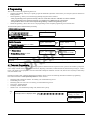
4 Programming
4 Programming
There are three methods of programming the PC9155
•
Template Programming - Allows you to quickly program the minimum required data. It also allows you to setup the system for DLS Downloading Software.
•
DLS Programming - Allows you to download programming using DLS-IV®™ Software.
- DLS programming can be performed locally with a PC-Link cable and a PC with DLS-IV software installed.
- DLS programming can be performed remotely via telephone line, GPRS network or the Internet.
- Setup for DLS can be accessed from Template Programming or Installer Programming modes.
•
Installer Programming - Allows direct access to all programming sections. Template programming is accessed from here.
Ensure that the System is disarmed before proceeding.
To Enter Installer programming:
Enter [ ][8][Installer Code]
The following screen will be displayed
E.g. ,
You are now in Installer Programming.
See Installer Programming para 4.3 for details
Enter Section
---
To Enter Template Programming:
Enter [899] on the “Enter Section” screen to enter
Template Programming.
The following screen will be displayed
Enter Section
---
See Template Programming para 4.1 for details.
To Enroll Wireless Devices:
Enter [898] on the “Enter Section” screen to
enroll Wireless Devices.
Enter Data
0111
T
F
A
The following screen will be displayed
Enter Section
---
See Enrolling Wireless Devices for details.
DLS Programming:
>
R
D
>
Wireless
Enrollment Mode
DLS Programming can be set up from Template programming (See Steps 3, 4 and 5 or from Installer Programming. See Programming Sections
[401]-[499].
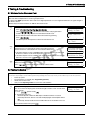
4.1 Template Programming
Template programming allows the Installer to quickly program the minimum functions required for basic operation. The installer is prompted to
enter a 4-digit code that selects predefined Zone Definitions, Reporting Code formats, Troubles & Restorals, and DLS setup (see Digit 1 - 4 tables
below). The installer is then prompted to enter the Central Station Telephone Number & Account Code, DLS Access Code, Entry & Exit Delays
and a new Installer Code.
Perform the following after completing the Hardware Installation. Ensure you have the following information available for programming.
Record this information in Alarm System Information for future reference.
•
•
•
•
•
•
Monitoring Station Telephone Number - Provided by your Alarm Monitoring Service.
Downloading Access Code.
Monitoring Station Account Code - Provided by your Alarm Monitoring Service.
Entry Delay - Installer Defined.
Exit Delay - Installer Defined.
Installer Code - User defined unique 4-digit code, default value is [5555].
Step
1
If “Ready to Arm” is displayed, Enter
,
System is
Ready to Arm
<>
Enter Section
---
4-1
PC9155 Wireless Alarm System
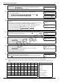
Step
2
When you are entered into the Programming Section, the 4-digit number “0111” will be
displayed. Enter
to accept the existing default programming.
See the tables below for details of Digit 1, 2, 3 and 4.
Step
3
After entering ‘0001’ the first telephone entry will be displayed. Enter the Monitoring Station
Telephone Number after the “D”. Do NOT delete any of the remaining “Fs”
E.g. To enter 02-1234-5678
Press
followed by
to complete the entry. See Section [301] for additional details.
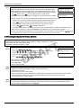
Step
4
After programming the first Telephone Number, the System Account Code will be
displayed.
The System Account Code can be any 6-digit combination of numbers (0-9) and Letters (AF). If the System Account Code is 4-digits the last two digits must be ‘FF’.
To Enter the Letters A through F, press
through F respectively. Press
,
,
the numbers 1 through 6 for the letter A
again to revert back to decimal entry.
,
E.g.: To Enter “1234FF” Press
See Section [310] for additional details.
Step
6
The Entry Delay is the amount of time you have to disarm the Alarm System after entering
the premises through a delay type zone before an alarm is sounded.
R
D
to accept the default time of 30 seconds (030) or
E.g. Press 020 for a delay of 20 seconds.
Step
7
The Exit Delay is the amount of time you have to exit the premises after pressing the Arm
key, before the alarm system is armed.
• Press
D0212345678FFFFF
FFFFFFFFFFFFFFFF
Enter Hex Data
FFFFFF
Enter Hex Data
1234FF
T
F
A
After programming the System Account Code, the Downloading Access Code will be
displayed. Enter the new Downloading Access code or press
to proceed to the next
step. See Section [403] for additional details.
• Enter an entry delay between 001 and 255.
DFFFFFFFFFFFFFFF
FFFFFFFFFFFFFFFF
.
Step
5
• Press
Enter Data
0111
to accept the default time of 120 seconds (120) or
Enter Hex Data
915500
Enter Data
030
Enter Data
120
• Enter an entry delay between 030 and 255.
E.g. Press 030 for a delay of 30 seconds.
Step
8
•
After programming the Exit Delay, the Installer Code will be displayed. Enter a 4 or 6-digit
code depending on the value in Section [701] Option 5.
Press
to exit Template Programming. See Section [006] for Installer Code details.
Digit 1 selects 1 of the following 7 options for Zone Definitions for the first 8 zones. A ‘0’ in the digit 1 location
indicates that the default settings for the first 8 zones are in place unless overridden during enrollment. See Section [001] for
defaults.
Option
Zn1
Zn2
Zn3
Zn4
Zn5
Zn6
Zn7
Zn8
1
01
03
03
03
04
04
04
04
01 Delay 1
2
01
03
03
05
05
05
05
88
02 Delay 2
3
01
03
03
05
05
05
05
87
03 Instant
4
01
01
03
03
03
03
03
03
04 Interior
5
01
03
03
06
05
05
05
05
05 Interior Stay/Away
6
01
03
03
06
05
05
05
88
06 Delayed Stay/Away
7
01
01
06
06
06
01
01
01
87 Delayed 24 Hr.
Refer to Chapter 5 for zone definition details
4-2
Enter Data
5555
Zone Definitions (Options 1- 7)
88 Standard 24 Hr. Fire
•
Digit 2 selects 1 of the following 6 options for Reporting Codes
Opt#
Phone Line 1
Programming Section Phone Line 3
1
2
Disabled
[380] Opt 1 OFF
Programming Section
SIA automatic Reporting Codes enabled [350] 1st Phone # [04]
[380] Opt 1 ON
[381] Opt 3 OFF
SIA Automatic Reporting Codes [350] 3rd Phone # [04]
Enabled
3
Contact ID Automatic Reporting Codes
enabled
SIA Automatic Reporting Codes [350] 3rd Phone # [04]
Enabled
[381] Opt [03] OFF
4
SIA automatic Reporting Codes enabled [350] 1st Phone #[04]
[380] Opt 1 ON
[381] Opt 3 OFF
Residential Dial
Enabled
[350] 3rd Phone # [06]
5
Contact ID Automatic Reporting Codes
enabled
[350] 1st Phone # [03]
[380] Opt 1 ON
[381] Opt 7 OFF
Residential Dial
Enabled
[350] 3rd Phone # [06]
6
Contact ID Automatic Reporting Codes
enabled
[350] 1st Phone # [03]
Contact ID Reporting Codes
[350] 3rd Phone # [03]
[380] Opt 1 ON
Enabled
Disabled
[350] 1st Phone # [03]
[380] Opt 1 ON
[381] Opt 7 OFF
[381] Opt 7 OFF
•
Digit 3 selects 1 of the 8 following options
Option
Common
Selected
Openings/
Zone
DLS/Installer
Group
Troubles
Closings
Restorals
Lead In/Out
1
2
3
4
5
6
7
8
R
D
indicates included, Blank indicates default setting,
Digit 3 - Table Headings/Descriptions
Common Group - Sets all Reporting Codes to Automatic
Description
Phone
#1
T
F
A
indicates disabled
Selected Troubles
Phone Sections
#3
Trouble
[345]
[346]
Alarms
Restoral
FF
FF
Set all Reporting Codes to automatic
[320] - [348] FF
Battery
Alarm/Restore call directions enabled
[351][1] ON, [3] OFF
AC Failure
00
00
Tamper/Restore Call directions disabled
[359][1] OFF, [3] OFF
Fire Trouble
FF
FF
Opening/Closing Call directions disabled
[367][1] OFF, [3] OFF
Aux PS
FF
FF
Maintenance Call Directions enabled
[375][1] ON, [3] OFF
TLM
XX
00
General System Trouble
00
00
Openings & Closings - Sets Residential Dial Reporting Codes for all openings and closings
DLS/Installer Lead-in/out
Users
Section
DLS Lead-in
[339]
Sect [347] Opt 4
1-8
CLOSINGS, Residential Dial Reporting codes
51
52
53
54
55
56
57
58
9-16
61
62
63
64
65
66
67
68
[339]
DLS Lead-out
40
99
FF
FF
FF
FF
XX
XX
XX
[341]
Sect [347] Opt 5
Section
Installer Lead-in
16
17
18
[342]
Sect [347] Opt 11
Users
1-8
OPENINGS, Residential Dial Reporting codes
11
12
13
14
15
9-16
21
22
23
24
25
26
27
28
[342]
Installer Lead-out
40
98
FF
XX
XX
XX
XX
XX
XX
[344]
Sect [347] Opt 11
[367]Opt 2 ON
Enabled for Options 8 only
Enable Opening/Closings call directions for Phone 2
FF=disabled, XX=Not Used
4-3
PC9155 Wireless Alarm System
Digit 4 indicates/selects 1 of the 3 following DLS Connections
Option
Double Call
Call Back
Sect [401] Opt 1
Sect [401] Opt 3
User Call Up
Sect [401] Opt 4
#Rings
Sect [406]
1
000
2
008
3
008
4
008
After the 4th digit is entered you will be prompted to enter the following data (refer to Chapter 5 for additional programming functions).
Entry 5
Central Station Telephone Number
- Enter 32 Character Telephone Number - See Section [301] for details
Entry 6
Central Station Account Code
- Enter the 6-digit code - See Section [310] for details
Entry 7
DLS Access Code
- Enter the 6-digit code - See Section [403] for details
Entry 8
Entry Delay 1, Exit Delay
- Enter Entry Delay 1 and Exit Delay - See Section [005] for details
Entry 9
Central Station Telephone Number
- Enter a 4 or 6-digit code depending on programming in Section [701] Option [5] - See Section [006] for details
4.2 DLS Programming
4.2.1 Local programming with PC-Link
Follow the steps below in the sequence indicated
Step
1
i
T
F
A
Ensure front cover is removed and the system is powered up
R
D
AC Power is required for PC-Link programming until battery is charged.
PC-Link Connections are ’Hot-swappable’.
Step
2
For systems with a GS2065 or TL265GS module installed, Disconnect the PC-link connector from the PC9155
module side first.
Step
3
Connect the PC-Link cable between the computer (with DLS Software installed and running) and the header pins
on the Alarm System.
Connecting the DLS PC to the Alarm system will automatically initiate a DLS session.
If the DLS session is not automatically initiated, enter [ ][8][Installer Code][499][Installer Code][499] to
manually initiate PC-Link (Refer to the DLS Software Help file for programming details).
Upon completion of the session, remove the PC-Link Cable from the alarm system and reconnect the cable from
the GPRS/Ethernet Module (if installed).
4.2.2 Remote Programming via Telephone Line
Refer to Section [401] DLS Downloading for setup details
2-way Wireless Keys:
After downloading a 2-way wireless key serial number to the PC9155, a button must be pressed on the wireless key
before it will become operational.
4.3 Installer Programming
Enter [ ][8][Installer Code]
You will be prompted to enter a 3-digit Programming Section number (refer to Chapter 5 for programming details).
4-4
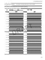
5.3 Programming Worksheets
5 Installer Programming
5.1 Index to Programming Options
Sect
Description
Pages
[000] Keypad Function Key Programming - - - - - - - - - - - - - - - - - - - - - 5-2/5-24
[001]-[002] Zone Definitions - - - - - - - - - - - - - - - - - - - - - - - - - - - - - - - 5-2/5-25
[005] System Timers - - - - - - - - - - - - - - - - - - - - - - - - - - - - - - - - - - - - 5-3/5-26
[006] Installer's Code- - - - - - - - - - - - - - - - - - - - - - - - - - - - - - - - - - - - 5-3/5-27
[007] Master Code - - - - - - - - - - - - - - - - - - - - - - - - - - - - - - - - - - - - - 5-3/5-27
[008] Maintenance Code - - - - - - - - - - - - - - - - - - - - - - - - - - - - - - - - - 5-3/5-27
[009] I/O Programming - - - - - - - - - - - - - - - - - - - - - - - - - - - - - - - - - - 5-3/5-27
[012] Keypad Lockout Options - - - - - - - - - - - - - - - - - - - - - - - - - - - - - 5-3/5-28
[013] First System Options- - - - - - - - - - - - - - - - - - - - - - - - - - - - - - - - 5-4/5-29
[014] Second System Options - - - - - - - - - - - - - - - - - - - - - - - - - - - - - 5-4/5-29
[015] Third System Options - - - - - - - - - - - - - - - - - - - - - - - - - - - - - - - 5-4/5-30
[016] Fourth System Options - - - - - - - - - - - - - - - - - - - - - - - - - - - - - - 5-4/5-30
[018] Sixth System Options - - - - - - - - - - - - - - - - - - - - - - - - - - - - - - - 5-4/5-31
[023] Tenth System Options- - - - - - - - - - - - - - - - - - - - - - - - - - - - - - - 5-5/5-31
[024] Eleventh System Options - - - - - - - - - - - - - - - - - - - - - - - - - - - - 5-5/5-31
[030] Zone Loop Response Options - - - - - - - - - - - - - - - - - - - - - - - - - 5-5/5-32
[101]-[134] Zone Attributes- - - - - - - - - - - - - - - - - - - - - - - - - - - - - - - - 5-5/5-32
[167] GPRS/Ethernet Interface Communications Wait for ACK - - - - - - 5-6/5-32
[168] Set Clock Forward (Daylight Saving) - - - - - - - - - - - - - - - - - - - - 5-6/5-33
[169] Set Clock Back (Standard Time) - - - - - - - - - - - - - - - - - - - - - - - 5-6/5-33
[170] PGM Output Timer - - - - - - - - - - - - - - - - - - - - - - - - - - - - - - - - - 5-6/5-33
[176] Cross Zone/Police Timer - - - - - - - - - - - - - - - - - - - - - - - - - - - - - 5-6/5-33
[190] No Activity Arming Pre-Alert Timer - - - - - - - - - - - - - - - - - - - - - - 5-6/5-33
[191] No Activity Timer - - - - - - - - - - - - - - - - - - - - - - - - - - - - - - - - - - 5-6/5-33
[202]-[206] Zone Assignments - - - - - - - - - - - - - - - - - - - - - - - - - - - - - 5-7/5-33
[301] First Telephone Number - - - - - - - - - - - - - - - - - - - - - - - - - - - - - 5-7/5-33
[302] Second Telephone Number - - - - - - - - - - - - - - - - - - - - - - - - - - - 5-7/5-34
[303] Third Telephone Number- - - - - - - - - - - - - - - - - - - - - - - - - - - - - 5-7/5-34
[304] Call Waiting Cancel String - - - - - - - - - - - - - - - - - - - - - - - - - - - - 5-7/5-34
[305] Fourth Telephone Number- - - - - - - - - - - - - - - - - - - - - - - - - - - - 5-7/5-34
[310] System Account Code- - - - - - - - - - - - - - - - - - - - - - - - - - - - - - - 5-7/5-34
[320]-[322] Alarm Reporting Codes (01-34) - - - - - - - - - - - - - - - - - - - - 5-7/5-34
[324]-[326] Alarm Restoral Reporting Codes (01-34) - - - - - - - - - - - - - 5-8/5-34
[328] Miscellaneous Alarm Reporting Codes - - - - - - - - - - - - - - - - - - - 5-8/5-34
[329] Priority Alarm and Restoral Reporting Codes- - - - - - - - - - - - - - - 5-8/5-35
[330]-[332] Tamper Reporting Codes - - - - - - - - - - - - - - - - - - - - - - - - 5-8/5-35
[334]-[336] Tamper Reporting Codes - - - - - - - - - - - - - - - - - - - - - - - - 5-9/5-35
[338] Miscellaneous Tamper Reporting Codes- - - - - - - - - - - - - - - - - - 5-9/5-35
[339] Closing (Arming) Reporting Codes - - - - - - - - - - - - - - - - - - - - - - 5-9/5-35
[341] Miscellaneous Closing (Arming) Reporting Codes - - - - - - - - - - - 5-9/5-35
[342] Opening (Disarming) Reporting Codes - - - - - - - - - - - - - - - - - - - 5-9/5-35
[344] Miscellaneous Opening (Disarming) Reporting Codes - - - - - - - - 5-9/5-36
[345] Maintenance Alarm Reporting Codes - - - - - - - - - - - - - - - - - - - 5-10/5-36
[346] Maintenance Restore Reporting Codes- - - - - - - - - - - - - - - - - - 5-10/5-36
[347] Miscellaneous Maintenance Reporting Codes - - - - - - - - - - - - - 5-10/5-36
[348] Test Transmission Reporting Codes - - - - - - - - - - - - - - - - - - - - 5-10/5-37
[350] Communicator Format Options - - - - - - - - - - - - - - - - - - - - - - - 5-10/5-37
[351]-[376] Call Direction Options - - - - - - - - - - - - - - - - - - - - - - - - - - 5-11/5-37
[377] Communication Variables - - - - - - - - - - - - - - - - - - - - - - - - - - - 5-11/5-37
[378] Test Transmission Time of Day - - - - - - - - - - - - - - - - - - - - - - - 5-11/5-38
[380] First Communicator Options - - - - - - - - - - - - - - - - - - - - - - - - - 5-11/5-38
[381] Second Communicator Options - - - - - - - - - - - - - - - - - - - - - - - 5-12/5-38
[382] Third Communicator Options - - - - - - - - - - - - - - - - - - - - - - - - - 5-12/5-39
[383] Fourth Communicator Options - - - - - - - - - - - - - - - - - - - - - - - - 5-12/5-39
[389] GPRS/Ethernet Fault Check Timer - - - - - - - - - - - - - - - - - - - - - 5-12/5-40
R
D
Sect
Description
[401] First Downloading Options - - - - - - - - - - - - - - - - - - - - - - - - - [402] Downloading Computer's Telephone Number - - - - - - - - - - - - [403] Downloading Access Code - - - - - - - - - - - - - - - - - - - - - - - - - [404] Panel Identification Code - - - - - - - - - - - - - - - - - - - - - - - - - - [405] Double Call Timer- - - - - - - - - - - - - - - - - - - - - - - - - - - - - - - - [406] Number of Rings to Answer On - - - - - - - - - - - - - - - - - - - - - - [499] Initiate PC-Link Downloading- - - - - - - - - - - - - - - - - - - - - - - - [501]-[502] PGM Attributes - - - - - - - - - - - - - - - - - - - - - - - - - - - - - [591]-[592] Inactivity Timers 1&2 Start and End Times - - - - - - - - - - [700] Automatic Clock Adjust - - - - - - - - - - - - - - - - - - - - - - - - - - - - [701] First International Options - - - - - - - - - - - - - - - - - - - - - - - - - - [702] Second International Options - - - - - - - - - - - - - - - - - - - - - - - [703] Delay between Dialing Attempts - - - - - - - - - - - - - - - - - - - - - [800] Door Chime Options (Zones 01-34) - - - - - - - - - - - - - - - - - - - -
Pages
5-12/5-40
5-12/5-40
5-12/5-40
5-12/5-41
5-12/5-41
5-13/5-41
5-13/5-41
5-13/5-41
5-14/5-42
5-14/5-42
5-14/5-42
5-14/5-42
5-14/5-43
5-15/5-43
[804] Wireless Programming - - - - - - - - - - - - - - - - - - - - - - - - - - - - -5-15/5-43
[804][001]-[032] Wireless Device Serial Numbers - - - - - - - - - - - - - - 5-15/5-43
[804][081] Wireless Supervisory Windows- - - - - - - - - - - - - - - - - - - - 5-15/5-43
[804][082]-[085] Zone Transmitter Supervision Options - - - - - - - - - - 5-16/5-43
[804][101]-[184] Wireless Key Programming - - - - - - - - - - - - - - - - - - 5-16/5-44
[804][201]-[204] Wireless Keypad Serial Numbers - - - - - - - - - - - - - - 5-16/5-44
[804][301]-[304] Wireless Siren Serial Numbers- - - - - - - - - - - - - - - - 5-16/5-44
[804][311]-[314] Wireless Siren Options - - - - - - - - - - - - - - - - - - - - - 5-16/5-44
[804][320] Global Siren Options - - - - - - - - - - - - - - - - - - - - - - - - - - - 5-17/5-45
[804][330] Maximum Siren Activation Time - - - - - - - - - - - - - - - - - - - 5-17/5-45
[804][900] General Wireless Options - - - - - - - - - - - - - - - - - - - - - - - 5-17/5-45
[851] GPRS/Ethernet Module Programming- - - - - - - - - - - - - - - - - - -5-17/5-45
[898] Wireless Device Enrollment- - - - - - - - - - - - - - - - - - - - - - - - - - 5-20/5-45
[899] Template Programming- - - - - - - - - - - - - - - - - - - - - - - - - - - - - 5-20/5-45
[900] Alarm System Version - - - - - - - - - - - - - - - - - - - - - - - - - - - - - 5-20/5-45
[904] Wireless Zone Module Placement Test- - - - - - - - - - - - - - - - - - 5-20/5-46
[905] Wireless Keypad Placement Test- - - - - - - - - - - - - - - - - - - - - - 5-20/5-46
[906] Wireless Siren Placement Test - - - - - - - - - - - - - - - - - - - - - - - 5-20/5-46
[990] Installer Lockout Enable - - - - - - - - - - - - - - - - - - - - - - - - - - - - 5-20/5-46
[991] Installer Lockout Disable - - - - - - - - - - - - - - - - - - - - - - - - - - - - 5-20/5-46
[996] Restore PC9x5x Wireless Device Factory Defaults - - - - - - - - - 5-20/5-46
[998] Restore PC9x5x (Panel Only) Factory Defaults - - - - - - - - - - - - 5-20/5-46
[999] Restore PC9x5x System Factory Defaults - - - - - - - - - - - - - - - 5-21/5-46
[4] Keypad Programming- - - - - - - - - - - - - - - - - - - - - - - - - - - - - - - -5-21/5-46
T
F
A
[001]-[034] Label Programming - - - - - - - - - - - - - - - - - - - - - - - - - - [065] Fire Alarm Label - - - - - - - - - - - - - - - - - - - - - - - - - - - - - - [066] Fail to Arm message - - - - - - - - - - - - - - - - - - - - - - - - - - - [067] Alarm When Armed Event Message - - - - - - - - - - - - - - - - [068] Command Output #1 Label - - - - - - - - - - - - - - - - - - - - - - [069] Command Output #2 Label - - - - - - - - - - - - - - - - - - - - - - [074] First Keypad Options - - - - - - - - - - - - - - - - - - - - - - - - - - - - - [075] Second Keypad Options - - - - - - - - - - - - - - - - - - - - - - - - - - - [076] Third Keypad Options - - - - - - - - - - - - - - - - - - - - - - - - - - - - - [077] LCD Message - - - - - - - - - - - - - - - - - - - - - - - - - - - - - - - - - - [078] Downloaded Message Duration - - - - - - - - - - - - - - - - - - - - - - [100] CO Detector Alarm Label - - - - - - - - - - - - - - - - - - - - - - - - - - [101] System Label - - - - - - - - - - - - - - - - - - - - - - - - - - - - - - - - - - - [996] Reset Label to Factory Defaults - - - - - - - - - - - - - - - - - - - - - - -
5-21/5-46
5-21/5-46
5-21/5-46
5-21/5-46
5-21/5-46
5-22/5-46
5-22/5-47
5-22/5-47
5-22/5-48
5-23/5-48
5-23/5-48
5-23/5-47
5-23/5-47
5-23/5-48
[997] Keypad Version - - - - - - - - - - - - - - - - - - - - - - - - - - - - - - - - - - 5-23/5-48
[998] Initiate Global Label Broadcast - - - - - - - - - - - - - - - - - - - - - - - 5-23/5-48
[999] Restore Factory Default Programming - - - - - - - - - - - - - - - - - - 5-23/5-48
5-1
PC9155 Wireless Alarm System
5. 2 Programming Worksheets - Standard (NA, CP-01, EU)
i
D ef
In d i ca te s d e fa u l t se tti n g s th a t a re co m m o n to a l l Al a rm Syste m ve rsi o n s co ve re d
NA
In d i ca te s d e fa u l t se tti n g s fo r N o rth Am e ri ca n Pa n e l s
CP
In d i ca te s d e fa u l t se tti n g s fo r C P-0 1 co m p l i a n ce
EU
In d i ca te s d e fa u l t se tti n g s fo r Eu ro p e a n Pa n e l s
Al l D e fa u l ts a re OFF u n l e ss i n d i ca te d o th e rw i se
[ 000] K ey pad Func t ion K ey P rogram m ing
[1]
[2]
[3]
[4]
[5]
Function Key
Function Key
Function Key
Function Key
Function Key
1 Assignment
2 Assignment
3 Assignment
4 Assignment
5 Assignment
NA
CP
EU
03
04
06
08
16
03
04
06
08
16
03
04
06
08
16
Func t ion K ey Opt ions
[00] Null Key
[01] Future Use
[02] Future Use
[03] Stay Arm
[04] Away Arm
[05] No Entry Arm
[06] Chime On/Off
[07] Future Use
[08] Bypass
[09] Future Use
[10] Future Use
[11] Future Use
[12] Future Use
[13] Command Output #1
[14] Command Output #2
[15] Future Use
[16] Quick Exit
[17] Reactivate Stay/Away Zones
D ef
Keypad 1
Keypad 2
Keypad 3
Keypad 4
R
D
Key 1
0
0
0
0
3
3
3
3
D ef
Key 2
0
0
0
0
4
4
4
4
D ef
Key 3
0
0
0
0
6
6
6
6
[25] Instant Stay Arm
*[27] Disarm
*[29] [A]ux Alarm
*[30] [P]anic
[33] Night Arm
T
F
A
D ef
*Applies to Key Fobs only
(See Section [804] Subsection [141]-[156])
Key 4
0
0
0
0
D ef
8
8
8
8
Key 5
1
1
1
1
6
6
6
6
[ 001] -[ 002] Zone Def init ions
00 Null Zone
14 24-Hour Heat
01 Delay 1
15 24-Hour Medical
02 Delay 2
* 16 24-Hour Panic
03 Instant
* 17 24-Hour Emergency
04 Interior
18 Future Use
05 Interior Stay/Away
* 19 24-Hour Water
06 Delay Stay/Away
* 20 24-Hour Freeze
07 Future Use
21 Future Use
08 Future Use
* 22 Momentary Keyswitch Arm
09 24-Hour Supervisory (Hardwired) * 23 Maintained Keyswitch Arm
10 24-Hour Supervisory Buzzer
24 Future Use
11 24-Hour Burglary
* 25 Interior Delay
12 Future Use
* 26 24-Hour Non-Alarm
13 24-Hour Gas
27 Future Use
* For burglary applications only ** For residential fire applications only
5-2
*
**
**
**
**
28 Future Use
29 Future Use
30 Future Use
31 Day Zone
32 Instant Stay/Away
33 Future Use
34 Future Use
35 Future Use
36 24-Hr Non-Latching Tamper
37 Night Zone
81 24-Hr Carbon Monoxide Detection (Wireless)
82 Audio Verification Monitor
87 Delay 24-Hr Fire (Wireless)
88 Standard 24-Hr Fire (Wireless)
89 Auto Verified Fire (Wireless)
5.3 Programming Worksheets
Sec t Z one N A C P EU
[001]
1
01 01 01
2
03 03 03
3
03 03 03
Z one N A C P EU
9
00 00 00
10 00 00 00
11 00 00 00
Sec t Z one N A C P EU
[002] 17 00 00 00
18 00 00 00
19 00 00 00
Z one N A C P EU
25 00 00 00
26 00 00 00
27 00 00 00
4
03 03 03
12
00 00 00
20
00 00 00
28
00 00 00
5
04 04 04
13
00 00 00
21
00 00 00
29
00 00 00
6
04 04 04
14
00 00 00
22
00 00 00
30
00 00 00
7
04 04 04
15
00 00 00
23
00 00 00
31
00 00 00
8
04 04 04
16
00 00 00
24
00 00 00
32
00 00 00
[ 005] S y s t em Timers
Valid entries for Entry Delay are between 030-255.
Sub Sec t.
[01]
Entry Delay 1
Sub Sec tions [02]- [08] ar e r es er v ed for futur e us e
N A 030 C P 030 EU 030
Entry Delay 2
[09]
i
i
i
Exit Delay
Bell Time Out (BTO)
045
030
045
120
060
120
004
004
004
F or SIA C P- 01 c ompliant ins tallations , the Ex it Delay mus t be within the r ange of 045- 255 s ec onds
If the Ex it D elay is s ilent ( Sec tion 14, O ption 6 or Stay F unc tion Key Ar ming) the ex it delay will be twic e the
pr ogr ammed v alue but mus t not ex c eed 255 s ec onds ( i.e., 090- 255 s ec onds ) .
[ 006] Ins t aller's Code
i
D ef
[ 007] Mas t er Code
[ 008] Maint enanc e Code
T hes e c odes ar e 4 or 6- digits ( pr ogr ammed in s ec tion[701] O pt [5]) .
F or 4- digit c odes the default is the fir s t 4 digits
R
D
555555
D ef
123456
P rogrammable Out put Opt ions
00
01
02
03
04
05
06
07
08
09
10
11
T
F
A
F or UL Ins tallations , the Entr y Delay plus the C ommunic ations Delay mus t not ex c eed 60 s ec onds .
D ef
AAAA00
Null PGM (Not Used)
12 TLM and Alarm
Residential Burglary and Fire Bell Output
13- 16 For Future Use
For Future Use
17 Away Armed Status
For Future Use
18 Stay Armed Status
For Future Use
19 Command Output #1 ([*][7][1])
System Armed Status
20 Command Output #2 ([*][7][2])
Ready To Arm
21- 32 For Future Use
Keypad Buzzer Follower
33 Bell Status & programming Access Output
Courtesy Pulse
34 For Future Use
System Trouble Output (with Trouble Options)
35 Zone Follower Output (Zones 9-16)
System Event Output (with Event Options)
40 Audio Verification trigger
System Tamper (all sources: zones, keypad)
[ 009] I/ O P rogramming
D ef
00
I/O Type (Zone 33, PGM 1)
Enter Zone or PGM Definition
D ef
00
I/O Type (Zone 34, PGM 2)
Enter Zone or PGM Definition
[ 012] K ey pad Loc k out Opt ions
i
If Key pad Loc k out is ac tiv e, the s y s tem c an not be dis ar med w ith a k ey s w itc h.
D ef
000
Number of Invalid Codes Before Lockout
(Valid entries are 000-255)
D ef
000
Lockout Duration (in minutes)
(Valid entries are 000-255)
5-3
PC9155 Wireless Alarm System
[ 013] Firs t S y s t em Opt ions
O pt
1
2
3
4
5
6
7
8
N A C P EU
9 9 9
9 9 9
9 9 9
ON
Hardwired Zone 33 Input Enabled
Hardwired Zone 34 Input Enabled
For Future Use
For Future Use
For Future Use
Audible Exit Fault Enabled
Event Buffer Follows Swinger Shutdown
Temporal Three Fire Signal Enabled
OFF
Pgm 1 Output Enabled
Pgm 2 Output Enabled
Audible Exit Fault Disabled
Event Buffer Logs Events Past Shutdown
Standard Pulsed Fire Signal
[ 014] S ec ond S y s t em Opt ions
O pt
1
2
3
4
5
6
7
8
N A C P EU
9 9 9
ON
Arm / Disarm Squawk Enabled
For Future Use
RF Jam Log After 5 Minutes
For Future Use
For Future Use
Audible Exit with Urgency
For Future Use
Fire Siren is Continuous
[ 015] Third S y s t em Opt ions
O pt
1
2
3
4
5
6
7
8
N A C P EU
9 9 9
9 9 9
9 9 9
9 9 9
1
2
3
4
5
6
7
8
N A C P EU
9
9 9 9
RF Jam Log After 20 sec
Silent Exit Delay
Fire Siren Follows Siren Cut-Off
T
F
A
ON
[F] Key Enabled
[P] Key Audible (Siren / Beeps)
Quick Exit Enabled
Quick Arming Enabled (*0 And Function Keys)
Code Required For Bypassing
Master Code Not Changeable
TLM Enabled
System Tamper Enabled
R
D
[ 016] Fourt h S y s t em Opt ions
O pt
OFF
Arm / Disarm Squawk Disabled
ON
Cross Zoning is Enabled
Exit Delay Restart Enabled
Blank Keypad When Not Used
Code Required To Remove Keypad Blanking
For Future Use
ID WKEY Not Required For Disarming
Bypass Status Displayed While Armed
Daylight Savings Time Enabled
OFF
[F] Key Disabled
[P] Key Silent
Quick Exit Disabled
Quick Arming Disabled (Funct. Keys Req. Code)
No Code Required
Master Code Changeable
TLM Disabled
System Tamper Disable
OFF
Police Code is Enabled
Exit Delay Restart Disabled
Keypad Active Always
No Code Required
ID WKEY Required For Disarming
Bypass Status Not Displayed While Armed
Daylight Savings Time Disabled
[ 018] S ix t h S y s t em Opt ions
O pt
1
2
3
4
5
6
7
8
5-4
N A C P EU
ON
For Future Use
Keypad Tampers Enabled
For Future Use
For Future Use
Keypad Buzzer Follows Siren Enabled
For Future Use
For Future Use
For Future Use
OFF
Keypad Tampers Disabled
Keypad Buzzer Follows Siren Disabled
5.3 Programming Worksheets
[ 023] Tent h S y s t em Opt ions
O pt
N A C P EU
1
2
3
4
5
*6
7
8
ON
For Future Use
For Future Use
Test Transmission While Armed Only
Test Transmission Counter In Hours
Switching From Away To Stay Disabled
For Future Use
Trouble Beeps Are Silent
Keyswitch Arms In Away Mode Only
OFF
Test Transmission While Armed/Disarmed
Test Transmission Counter In Days
Away To Stay Toggle Option Permitted
Trouble Beeps Will Sound Every 10 Seconds
Keyswitch Arms In Stay Or Away
[ 024] E lev ent h S y s t em Opt ions
O pt
1
2
3
4
5
*6
7
8
N A C P EU
9 9 9
9
9
9 9 9
9 9 9
ON
Temperature Display Enabled
Temperature Displayed in Celsius
PC9155 Internal Siren Enabled
Inactivity monitored by all zones
For Future Use
For Future Use
For Future Use
For Future Use
[ 030] Zone Loop Res pons e Opt ions
O pt
N A C P EU
1
2
ON
Zone 33 is Fast Loop Response
Zone 34 is Fast Loop Response
OFF
Temperature Display Disabled
Temperature Displayed In Fahrenheit
PC9155 Internal Siren Disabled
Inactivity monitored only by 24 Hr Non-alarm zones
T
F
A
OFF
Zone 33 is Normal Loop Response
Zone 34 is Normal Loop Response
[ 101] -[ 134] Zone A t t ribut es (A t t ribut es 10-13 are res erv ed f or Fut ure Us e)
Attri b u te :
Zo n e Typ e
R
D
00 Null Zone
01 Delay 1
02 Delay 2
03 Instant
04 Interior
05 Interior Stay/Away
06 Delay Stay/Away
07 Future Use
08 Future Use
09 24-Hour Supervisory (Hardwired)
10 24-Hour Supervisory Buzzer
11 24-Hour Burglary
12 Future Use
13 24-Hour Gas
14 24-Hour Heat
15 24-Hour Medical
16 24-Hour Panic
17 24-Hour Emergency
18 Future Use
19 24-Hour Water
20 24-Hour Freeze
21 Future Use
22 Momentary Keyswitch Arm
23 Maintained Keyswitch Arm
24 Future Use
1
2
3
4
5
6
7
8
9
14
15
16
9= ON Audible Steady Chime Bypass Force Swing TX Dly X-Zone 2-way NC SEOL DEOL
No
No
No
No
OFF Silent Pulsed No
No Audio Loops
9
9
9
9
9
9
9
9
9
9
9
9
9
9
9
9
9
9
9
9
9
9
9
9
9
9
9
9
9
9
9
9
9
9
9
9
9
9
9
9
9
9
9
9
9
9
9
9
9
9
9
9
9
9
9
9
9
9
9
9
9
9
9
9
9
9
9
9
5-5
PC9155 Wireless Alarm System
Attri b u te :
Zo n e Typ e
1
25 Interior Delay
26 24-Hour Non-Alarm
27 Future Use
28 Future Use
29 Future Use
30 Future Use
31 Day Zone
32 Instant Stay/Away
33 For Future Use
34 For Future Use
35 Future Use
36 24-Hr Non-Latching Tamper
37 Night Zone
81 24-Hr Carbon Monoxide Detection (Wireless)
82 Audio Verification Monitor
87 Delay 24-Hr Fire (Wireless)
88 Standard 24-Hr Fire (Wireless)
89 Auto Verified Fire (Wireless)
i
i
2
3
4
5
6
7
8
9
14
15
16
9= ON Audible Steady Chime Bypass Force Swing TX Dly X-Zone 2-way NC SEOL DEOL
No
No
No
No
No Audio Loops
OFF Silent Pulsed No
9
9
9
9
9
9
9
9
9
9
9
9
9
9
9
9
9
9
9
9
9
9
9
9
9
9
9
9
9
9
9
T
F
A
* F or UL ins tallations , do not c hange attr ibute 5 ( F or c e Ar ming) fr om the default s etting.
F or CP- 01 ins tallations :
O ption 6 ( Swinger ) is defaulted O N for z one definitions 09- 11, 13- 17, 19, 20
O ption 7 ( T X Delay ) is defaulted O N for z one definitions 01- 06, 09- 11, 13- 17, 19, 20, 25, 32, 36, 37.
R
D
[ 167] GP RS / E t hernet Int erf ac e Communic at ions Wait For A c k
N A 020 C P 020 EU 020
Valid Entries 001-255 seconds
[ 168] S et Cloc k Forward (Day light S av ing)
N A C P EU
Month
003 003 003
Week
002 002 005
Day
000 000 000
Hour
002 002 001
Increment
001 001 001
Valid Entries 001-012
[ 169] S et Cloc k B ac k (S t andard Time)
N A C P EU
Month
011 011 010
Valid Entries 001-012
Week
001 001 005
Valid Entries 001-005
Valid Entries 000-031
Day
000 000 000
Valid Entries 000-031
Valid Entries 000-023
Hour
002 002 001
Valid Entries 000-023
Valid Entries 001-002
Decrement 001 001 001
Valid Entries 001-002
Valid Entries 001-005
[ 170] P GM Out put Timer
N A 005 C P 005 EU 005
Valid Entries 001-255 seconds
[ 176] Cros s Zone/ P olic e Code Timer
N A 060 C P 060 EU 060
Valid Entries 001-255 seconds/minutes
[ 190] No A c t iv it y A rming P re-A lert Timer
N A 001 C P 001 EU 001
Valid Entries 001-255 minutes, 000 for no pre-alert
[ 191] No A c t iv it y A rming Timer
N A 000 C P 000 EU 000
5-6
Valid Entries 001-255 minutes, 000 to disable
5.3 Programming Worksheets
[ 202] -[ 206] Zone A s s ignment s
[202] Z one 1- 8
O pt.
1
2
3
4
5
6
7
8
N A C P EU
9
9
9
9
9
9
9
9
9
9
9
9
9
9
9
9
9
9
9
9
9
9
9
9
[203] Z one 9- 16
N A C P EU
Zone 1
Zone 2
Zone 3
Zone 4
Zone 5
Zone 6
Zone 7
Zone 8
[204] Z one 17- 24
N A C P EU
Zone 9
Zone 10
Zone 11
Zone 12
Zone 13
Zone 14
Zone 15
Zone 16
[205] Z one 25- 32
N A C P EU
Zone 17
Zone 18
Zone 19
Zone 20
Zone 21
Zone 22
Zone 23
Zone 24
[206] Z one 33- 34
N A C P EU
Zone 25
Zone 26
Zone 27
Zone 28
Zone 29
Zone 30
Zone 31
Zone 32
Zone 33
Zone 34
Future Use
Future Use
Future Use
Future Use
Future Use
Future Use
[ 301] Firs t Telephone Number (32 Digit s )
D
[ 302] S ec ond Telephone Number (32 Digit s )
D
[ 303] Third Telephone Number (32 Digit s )
D
[ 304] Call Wait ing Canc el S t ring
D ef
i
DB70EF
T
F
A
All s ix digits mus t be enter ed for c hanges to be s av ed. Pr ogr am unus ed digits with ‘F ’.
[ 305] Fourt h Telephone Number (32 Digit s )
D
R
D
[ 310] S y s t em A c c ount Code
Enter a 6-digit account number for the system account code. Only SIA supports 6-digit account codes. If a 4-digit code is
used, program the last two digits of the account code with FF.
D ef
FFFFFF
Reporting Codes
i
All Repor ting Codes ar e defaulted ‘F F ’ unles s indic ated other wis e.
[3 2 0 ]-[3 2 2 ] Al a rm R e p o rti n g C o d e s, Zo n e s 0 1 -3 4
[ 320]
[ 321]
[ 322]
Zone 1
Zone 2
Zone 3
Zone 4
Zone 5
Zone 6
Zone 7
Zone 8
Zone 9
Zone 10
Zone 11
Zone 12
Zone13
Zone 14
Zone 15
Zone 16
Zone 17
Zone 18
Zone 19
Zone 20
Zone 21
Zone 22
Zone 23
Zone 24
Zone 25
Zone 26
Zone 27
Zone 28
Zone 29
Zone 30
Zone 31
Zone 32
Zone 33
Zone 34
5-7
PC9155 Wireless Alarm System
[3 2 4 ]-[3 2 6 ] Al a rm R e sto ra l R e p o rti n g C o d e s, Zo n e s 0 1 -3 4
[ 324]
[ 325]
[ 326]
Zone 1
Zone 2
Zone 3
Zone 4
Zone 5
Zone 6
Zone 7
Zone 8
Zone 9
Zone 10
Zone 11
Zone 12
Zone13
Zone 14
Zone 15
Zone 16
Zone 17
Zone 18
Zone 19
Zone 20
Zone 21
Zone 22
Zone 23
Zone 24
Zone 25
Zone 26
Zone 27
Zone 28
Zone 29
Zone 30
Zone 31
Zone 32
Zone 33
Zone 34
[3 2 8 ] Mi sce l l a n e o u s Al a rm R e p o rti n g C o d e s
Duress Alarm
Opening After Alarm
Recent Closing
For Future Use
For Future Use
Cross Zone / Police Code Alarm
Burglary Not Verified
Alarm Cancelled
R
D
[3 2 9 ] Pri o ri ty Al a rm An d R e sto re R e p o rti n g C o d e s
Keypad [F]ire Alarm
Keypad [A]uxiliary Alarm
Keypad [P]anic Alarm
Fail to Report In
Keypad [F]ire Restore
Keypad [A]uxiliary Restore
T
F
A
Keypad [P]anic Restore
For Future Use
[3 3 0 ]-[3 3 2 ] Ta m p e r R e p o rti n g C o d e s
Se cti o n
[ 330]
[ 331]
[ 332]
5-8
Zone 1
Zone 2
Zone 3
Zone 4
Zone 5
Zone 6
Zone 7
Zone 8
Zone 9
Zone 10
Zone 11
Zone 12
Zone13
Zone 14
Zone 15
Zone 16
Zone 17
Zone 18
Zone 19
Zone 20
Zone 21
Zone 22
Zone 23
Zone 24
Zone 25
Zone 26
Zone 27
Zone 28
Zone 29
Zone 30
Zone 31
Zone 32
Zone 33
Zone 34
5.3 Programming Worksheets
[3 3 4 ]-[3 3 6 ] Ta m p e r R e sto ra l R e p o rti n g C o d e s
Se cti o n
[ 334]
[ 335]
[ 336]
Zone 1
Zone 2
Zone 3
Zone 4
Zone 5
Zone 6
Zone 7
Zone 8
Zone 9
Zone 10
Zone 11
Zone 12
Zone13
Zone 14
Zone 15
Zone 16
Zone 17
Zone 18
Zone 19
Zone 20
Zone 21
Zone 22
Zone 23
Zone 24
Zone 25
Zone 26
Zone 27
Zone 28
Zone 29
Zone 30
Zone 31
Zone 32
Zone 33
Zone 34
[3 3 8 ] Mi sce l l a n e o u s Ta m p e r R e p o rti n g C o d e s
General System Tamper
General System Tamper Rest
Keypad Lockout
T
F
A
[3 3 9 ] C l o si n g (Arm i n g ) R e p o rti n g C o d e s- Acce ss C o d e s 1 -1 6
Se cti o n
[ 339]
Code 1
Code 2
Code 9
Code 10
Code 3
Code 4
R
D
Code 11
Code 12
Code 5
Code 6
Code 7
Code 8
Code 13
Code 14
Code 15
Code 16
[3 4 1 ] Mi sce l l a n e o u s C l o si n g (Arm i n g ) R e p o rti n g C o d e s
Closing By Access Code 40
Automatic Zone Bypass
Partial Closing
Special Closing
Exit Fault
[3 4 2 ] Op e n i n g (D i sa rm i n g ) R e p o rti n g C o d e s- Acce ss C o d e s 1 -1 6
[ 342]
Code 1
Code 2
Code 3
Code 4
Code 5
Code 6
Code 7
Code 8
Code 9
Code 10
Code 11
Code 12
Code 13
Code 14
Code 15
Code 16
[3 4 4 ] Mi sce l l a n e o u s Op e n i n g (D i sa rm i n g ) R e p o rti n g C o d e s
Opening By Access Code 40
Special Opening
Late To Open
5-9
PC9155 Wireless Alarm System
[3 4 5 ] Ma i n te n a n ce Al a rm R e p o rti n g C o d e s
Battery Trouble Alarm
AC Failure Trouble Alarm
For Future Use
Fire Trouble Alarm
Auxiliary Power Supply Trouble Alarm
TLM Alarm
General System Trouble
For Future Use
[3 4 6 ] Ma i n te n a n ce R e sto re R e p o rti n g C o d e s
Battery Trouble Restore
AC Failure Trouble Restore
For Future Use
Fire Trouble Restore
Auxiliary Power Supply Trouble Restore
TLM Restore
General System Trouble Restore
For Future Use
[3 4 7 ] Mi sce l l a n e o u s Ma i n te n a n ce R e p o rti n g C o d e s
Phone #1 FTC Restore
Phone #2 FTC Restore
For Future Use
0 0
0 0
R
D
DLS Lead In
DLS Lead Out
General Zone Fault Alarm
General Zone Fault Restore
Delinquency Reporting Code
General Zone Low Battery Alarm
General Zone Low Battery Restore
0 0
0 0
T
F
A
Installer Lead Out
Installer Lead In
Phone #3 FTC Restore
Phone #4 FTC Restore
[3 4 8 ] Te st Tra n sm i ssi o n R e p o rti n g C o d e s
Walk Test End
Walk Test Begin
GPRS/Ethernet Periodic Test Transmission
Periodic Test Transmission
System Test
[ 350] Communic at or Format Opt ions
1st Telephone Number
NA
04 C P 04 EU 04
2nd Telephone Number
NA
04 C P 04 EU 04
3rd Telephone Number
NA
04 C P 04 EU 04
01
20 BPS, 1400 Hz
02 20 BPS, 2300 Hz
03 DTMF Contact ID
05
Future Use
* 06 Residential Dial
* Failure to communicate using Residential Dial will not generate a FTC trouble.
5-10
4th Telephone Number
NA
04 C P 04 EU 00
04 SIA FSK
5.3 Programming Worksheets
[ 351] -[ 376] Call Direc t ion Opt ions
[ 351] A larm/ Res t ore Communic at or Call Direc t ions
O pt 1
1s t T elephone
D ef
9
O pt 2
2nd T elephone
D ef
O pt 3
3r d T elephone
O pt 4
4th T elephone
D ef
D ef
O pt 5- 8
F or F utur e Us e
D ef
[ 359] Tamper A larm/ Res t ore Communic at or Call Direc t ions
Op t 1
Op t 2
Op t 3
Op t 4
Op t 5 -8
1s t T elephone
2nd T elephone
3r d T elephone
4th T elephone
F or F utur e Us e
D ef
9
D ef
D ef
D ef
D ef
[ 367] Opening/ Clos ing Communic at or Call Direc t ions
Op t 1
Op t 2
Op t 3
Op t 4
Op t 5 -8
1s t T elephone
2nd T elephone
3r d T elephone
4th T elephone
F or F utur e Us e
D ef
D ef
D ef
D ef
D ef
[ 375] S y s t em Maint enanc e A larm/ Res t ore Communic at or Call Direc t ions
Op t 1
Op t 2
Op t 3
Op t 4
Op t 5 -8
1s t T elephone
2nd T elephone
3r d T elephone
4th T elephone
F or F utur e Us e
D ef
9
D ef
D ef
T
F
A
D ef
D ef
[ 376] S y s t em Tes t Trans mis s ions Communic at or Call Direc t ions
Op t 1
Op t 2
Op t 3
1s t T elephone
2nd T elephone
3r d T elephone
D ef
9
D ef
R
D
D ef
[ 377] Communic at ion V ariables
N A 003 C P 001 EU 003
Op t 4
Op t 5 -8
4th T elephone
F or F utur e Us e
D ef
D ef
Swinger Shutdown (Alarms & Rest)
000-014, 000=Disabled
003
003
003
Swinger Shutdown (Tampers & Rest)
000-014, 000=Disabled
003
003
003
Swinger Shutdown (Maint & Rest)
000-014, 000=Disabled
000-255 Seconds, 000 = No Delay
000
030
000
Communication Delay
030
030
030
AC Failure Communication Delay
010
010
010
TLM Trouble Delay
000-255 x 3 Seconds, 000 = No Delay
030
030
Test Transmission Cycle (Land-Line)
000-255 Hrs/Days, 000=disabled
060
060
060
GPRS/Ethernet Test Transmission Cycle
000-255 Hrs/Days, 000=disabled
007
007
007
Wireless Device Low Battery Transmission Delay
000-255 Days, 000 = No Delay
030
030
030
Delinquency Transmission Delay
000-255 Hrs/Days, 000=disabled
000
005
000
Communications Cancel Window
005-255 Minutes (CP-01 Only)
030
000-255 Mins/Hrs, 000 = No Delay
[ 378] Tes t Trans mis s ion Time of Day
D ef
9999
Valid entries are (0000-2359), 9999 to disable
[ 380] Firs t Communic at or Opt ions
O pt
1
2
3
4
5
6
7
8
N A C P EU
9 9 9
ON
Communications Enabled
Restores On Siren Time-Out
Pulse Dialing
For Future Use
For Future Use
Alternating Backup Dial
For Future Use
Delinquency Follows Zone Activity (Hours)
OFF
Communications Disabled
Restores Follow Zones
DTMF Dialing
Call Primary Number, Backup To Secondary
Delinquency Follows Arming (Days)
5-11
PC9155 Wireless Alarm System
[ 381] S ec ond Communic at or Opt ions
O pt
N A C P EU
1
2
3
4
5
6
7
8
ON
Opening After Alarm Kypd Ringback Enabled
For Future Use
SIA Uses Programmed Rep. Codes
Closing Confirmation Enabled
For Future Use
For Future Use
Contact I.D. Uses Pgm’d Rep. Codes
For Future Use
OFF
Opn After Alrm Kypd Ringback Disabled
SIA Uses Automatic Rep. Codes
Closing Confirmation Disabled
Contact I.D. Uses Auto Rep. Codes
[ 382] Third Communic at or Opt ions
O pt
N A C P EU
1
2
3
4
5
6
7
8
9
ON
Contact I.D. Partial Closing Identifier is 5
Alarm Comms During Walk Test Enabled
Communications Cancelled Message Enabled
Call Waiting Cancel Enabled
GPRS/Ethernet Module Enabled
System AC Failure Communication Delay In Hours
# of Dialing Attempts is 1 For Residential Dial
For Future Use
[ 383] Fourt h Communic at or Opt ions
O pt
1
2
3
4
5
6
7
8
N A C P EU
9 9 9
9 9
D ef
T
F
A
ON
For Future Use
Phone Number 2 Backs Up Number 1
Phone Number 3 Backs Up Number 2
Phone Number 4 Backs Up Number 3
FTC’ed Events Communicate
Account Code Error Check Enabled
For Future Use
For Future Use
R
D
[ 389] GP RS / E t hernet Fault Chec k Timer
OFF
Contact I.D. Partial Closing Identifier is 4
Alarm Comms During Walk Test Disabled
Communications Cancelled Message Disabled
Call Waiting Cancel Disabled
GPRS/Ethernet Module Disabled
System AC Failure Communication Delay In Minutes
# of Dialing Attempts is 5 For Residential Dial
OFF
Phone Number 2 is Independent
Phone Number 3 is Independent
Phone Number 4 is Independent
FTC’ed Events Do Not Communicate
Account Code Error Check Disabled
Valid entries are 003-255 x 3 seconds (E.g., 003x3 = 9 seconds).
003
[ 401] Firs t Downloading Opt ions
O pt
1
2
3
4
5
6
7
8
N A C P EU
9 9 9
ON
Answering Machine / Double Call Enabled
User Enable DLS
Call-Back Enabled
User Initiated Call-Up Enabled
For Future Use
Call Up is 300 Baud
For Future Use
For Future Use
OFF
Answ. Machine / Double Call Disabled
User Can Not Enable DLS Window
Call-Back Disabled
User Initiated Call-Up Disabled
Call Up is 110 Baud
[ 402] Downloading Comput er's Telephone Number (32 Digit s )
D
[ 403] Downloading A c c es s Code
N A 915500
C P 915500
EU 915500
[ 404] P anel Ident if ic at ion Code
N A 915500
[ 405] Double Call Timer
N A 030 C P 030 EU 030
5-12
Valid entries are (000-255) seconds
C P 915500
EU 915500
5.3 Programming Worksheets
[ 406] Number of Rings To A ns wer On
Valid entries are (000-255) rings
N A 000 C P 000 EU 000
[ 499] Init iat e P C-Link Downloading
Enter [ 499] [ Ins t aller Code] [ 499] to initiate downloading
[ 501] -[ 502] P GM A TTRIB UTE S (bit s 1 t o 8)
PGM Attribute Defaults (OFF unless indicated otherwise)
1
2
Attri b u te :
4
5
6
7
8
9
9
9
9
9
9
9
9
9
9
9
9
5
6
Zone
7
Zone Low
8
Loss of
Zone Fault
Disabled
Tamper
Disabled
Battery
Disabled
Clock
Disabled
3
9 ON Not Used Not Used True Output Follows Timer Code Req. Not Used Not Used Not Used
ON/OFF
Inverted
No Code
No
No
No
OFF
PGM Op ti o n
00 Null Pgm (Not Used)
01 Burglary And Fire Siren Output
02 Not Used
03 Not Used
04 Not Used
05 Armed Status
06 Ready To Arm
07 Keypad Buzzer Follow
08 Courtesy Pulse
* 09 System Trouble Output (with Trouble
* 10 System Event (with Event Options)
11 System Tamper (All Sources)
12 Tlm And Alarm
13 Not Used
14 Not Used
15 Not Used
16 Not Used
17 Away Armed Status
18 Stay Armed Status
19 Command Output #1 (*71)
20 Command Output #2 (*72)
30 Future Use
* 40 Audio Verification Trigger
9
9
9
9
9
9
9
9
9
9
9
9
9
R
D
* Attributes for Option 9, 10 & 40
Attri b u te :
09 S y s t em Trouble
ON
OFF
Attri b u te :
10 S y s t em E v ent
ON
OFF
40 A udio V erif ic at ion Trigger
P GM
[ 501]
[ 502]
1
2
Event
Disabled
P GM Ty pe
2
3
4
AC Fail TLM Fault
FTC
Disabled Disabled Disabled
9
9
9
9
9
9
9
9
1
2
Fire
3
Panic
4
Medical
5
Supervisory
6
Priority
7
Duress
8
Follows
Event
Disabled
Event
Disabled
Event
Disabled
Event
Disabled
Event
Disabled
Event
Disabled
Timer
Latched
9
9
9
9
9
9
9
1
2
Opening
3
4
5
6
7
Tampers
& Closing
[A] Key
[P] Key
Duress Alarm
Priority
Enabled
Disabled
Enabled
Disabled
Enabled
Disabled
Enabled
Disabled
Enabled
Disabled
ON Burg Event
OFF Disabled
Attri b u te :
S ec t
1
Service Req
T
F
A
9
9
9
9
1
2
3
4
5
8
Event
Not Used Not Used
Disabled
6
7
8
5-13
PC9155 Wireless Alarm System
[ 591-592] Inac t iv it y Timers 1 & 2 S t art and E nd Times
S ec t
[ 591] Timer #1
[ 591] Timer #2
NA
CP
EU
9999
9999
9999
9999
9999
9999
S t art Time
NA
CP
EU
9999
9999
9999
9999
9999
9999
E nd Time
Valid times are
00:00 - 23:59 Hrs
9999 to disable
[ 609] Module Tamper Report ing Codes
Keypad 1 Tamper
Siren 1 Tamper
Keypad 2 Tamper
Siren 2 Tamper
Keypad 3 Tamper
Siren 3 Tamper
Keypad 4 Tamper
Siren 4 Tamper
Keypad 1 Tamper Restore
Siren 1 Tamper Restore
Keypad 2 Tamper Restore
Siren 2 Tamper Restore
Keypad 3 Tamper Restore
Siren 3 Tamper Restore
Keypad 4 Tamper Restore
Siren 4 Tamper Restore
[ 700] A ut omat ic Cloc k A djus t
NA
Valid entries are (00-99) seconds
60 C P 60 EU 60
[ 701] Firs t Int ernat ional Opt ions
O pt
N A C P EU
1
2
3
4
5
6
7
8
9
9
R
D
[ 702] S ec ond Int ernat ional Opt ions
O pt
1
2
3
4
5
6
7
8
N A C P EU
9
9
T
F
A
ON
50 Hz AC Input
Time Base is Internal Crystal
AC/DC Arming Inhibit Enabled
All System Tampers Require Installer Reset
6-Digit User Access Codes
Busy Tone Detection Enabled
For Future Use
For Future Use
ON
Pulse Dialing Make/Break Ratio is 33/67
Force Dialing Enabled
For Future Use
1600 Hz Handshake
ID Tone Enabled
2100 Hz ID Tone
For Future Use
For Future Use
[ 703] Delay B et ween Dialing A t t empt s
N A 003 C P 003 EU 003
5-14
Valid entries are (000-255) minutes
OFF
60 Hz AC Input
Time Base is AC Line
AC/DC Arming Inhibit Disabled
All System Tampers Follow Restore
4-Digit User Access Codes
Busy Tone Detection Disabled
OFF
Pulse Dialing Make/Break Ratio is 40/60
Force Dialing Disabled
Standard Handshake
ID Tone Disabled
1300 Hz ID Tone
5.3 Programming Worksheets
[ 800] Door Chime Opt ions f or Zones 01-34
Opt ion
Sec t
[01]
[02]
[03]
[04]
[05]
[06]
[07]
[08]
[09]
[10]
[11]
[12]
[13]
[14]
[15]
[16]
[17]
1
ON
OFF
2
3
B ing B ing D ing D o ng
D is a ble d
D is a ble d D is a ble d
Z one
1
2
3
4
5
6
7
8
9
10
11
12
13
14
15
16
17
D ef
D ef
Opt ion
4
6 B e e ps
A la rm
D is a ble d
D ef
Sec t
[18]
[19]
[20]
[21]
[22]
[23]
[24]
[25]
[26]
[27]
[28]
[29]
[30]
[31]
[32]
[33]
[34]
D ef
9
9
9
9
9
9
9
9
9
9
9
9
9
9
9
9
9
[ 804] Wireles s Dev ic e P rogramming
2
[002]
3
[003]
4
[004]
5
[005]
6
[006]
R
D
7
1
ON
OFF
2
3
6 B e e ps
B ing B ing D ing D o ng
D is a ble d
D is a ble d D is a ble d
Z one
18
19
20
21
22
23
24
25
26
27
28
29
30
31
32
33
34
D ef
D ef
4
A la rm
D is a ble d
D ef
D ef
9
9
9
9
9
9
9
9
9
9
9
9
9
9
9
9
9
T
F
A
[ 804] [ 001] -[ 032] Wireles s Dev ic e S erial Numbers
Zone S ub
S ec t .
1 [001]
S erial Number
Zone S ub
S ec t .
12 [012]
13
[013]
14
[014]
15
[015]
16
S erial Number
Zone S ub
S ec t .
23 [023]
24
[024]
25
[025]
26
[026]
[016]
27
[027]
17
[017]
28
[028]
[007]
18
[018]
29
[029]
8
[008]
19
[019]
30
[030]
9
[009]
20
[020]
31
[031]
10
[010]
21
[021]
32
[032]
11
[011]
22
[022]
S erial Number
[ 804] [ 081] Wireles s S uperv is ory Windows
NA
96 C P 96 EU 08
1-way Wireless Supervisory Window
96
2-way Wireless Supervisory Window
96
08
Value = Entry x 15 minutes. E.g., 6x15 minutes equals 1.5 hrs. Valid entries are 4-96 (1Hr - 24Hr)
5-15
PC9155 Wireless Alarm System
[ 804] [ 082] -[ 085] Zone Trans mit t er S uperv is ion Opt ions
[0 8 2 ]
[0 8 3 ]
[0 8 4 ]
[0 8 5 ]
Opt ion
Zone
D ef
Zone
D ef
Zone
D ef
Zone
D ef
1
2
3
4
5
6
7
8
1
2
3
4
5
6
7
8
9
9
9
9
9
9
9
9
9
10
11
12
13
14
15
16
9
9
9
9
9
9
9
9
17
18
19
20
21
22
23
24
9
9
9
9
9
9
9
9
25
26
27
28
29
30
31
32
9
9
9
9
9
9
9
9
[ 804] [ 101] -[ 184] Wireles s K ey P rogramming (1-way & 2-way dev ic es )
E nable/ Dis able
Func t ion k ey P rogramming
Sub
S erial Number
Sec t.
Sub
Sec t.
1
[101]
[141]
[181] 9
2
[102]
[142]
9
3
[103]
[143]
9
4
[104]
[144]
5
[105]
[145]
6
[106]
[146]
7
[107]
8
[108]
#1
03
D ef
#2
04
D ef
R
D
[147]
[148]
#3
27
D ef
#4
30
D ef
#5
D ef
13
#6
14
D ef
T
F
A
Func t ion k ey P rogramming (c ont . )
Sub
S erial Number
Sec t.
9
Sub
Sec t.
#1
D ef 03
#2
D ef 04
[149]
[109]
#3
D ef 27
#4
D ef 30
#5
D ef
13
#6
D ef 14
Sub
Sec t.
D ef
9
9
9
9
9
E nable/ Dis able
Sub
Sec t.
D ef
[182] 9
[150]
9
[151]
9
12 [112]
[152]
9
13 [113]
[153]
9
14 [114]
[154]
9
15 [115]
[155]
9
16 [116]
[156]
9
10 [110]
11 [111]
[ 804] [ 201] -[ 204] Wireles s K ey pad S erial Numbers
K ey pad
1
5-16
S ub
S ec t .
S erial Number
[ 804] [ 301] -[ 304] Wireles s S iren S erial Numbers
S iren
S ub
S ec t .
[201]
1
2
[202]
2
[302]
3
[203]
3
[303]
4
[204]
4
[304]
[301]
S erial Number
5.3 Programming Worksheets
[ 804] [ 311] Wireles s S iren #01 Opt ions
O pt
1
2
3
4
5
6
7
8
N A C P EU
9
9
9
9
9 9
9
9
9
9
9
9
ON
Siren Alarm Enabled
Buzzer Notifications Enabled
Door Chime Enabled
Trouble Beeps Enabled
Squawks Enabled
Enable Strobe
Buzzer Alarm / Strobe Follows BTO
Siren Tamper Enabled
OFF
Siren Alarm Disabled
Buzzer Notifications Disabled
Door Chime Disabled
Trouble Beeps Disabled
Squawks Disabled
Disable Strobe
Buzzer Alarm / Strobe Follows Alarm Condition
Siren Tamper Disabled
[ 804] [ 312] Wireles s S iren #02 Opt ions
O pt
1
2
3
4
5
6
7
8
N A C P EU
9
9
9
9
9 9
9
9
9
9
9
9
ON
Siren Alarm Enabled
Buzzer Notifications Enabled
Door Chime Enabled
Trouble Beeps Enabled
Squawks Enabled
Enable Strobe
Buzzer Alarm / Strobe Follows BTO
Siren Tamper Enabled
[ 804] [ 313] Wireles s S iren #03 Opt ions
O pt
1
2
3
4
5
6
7
8
N A C P EU
9
9
9
9
9 9
9
9
9
9
9
9
O pt
1
2
3
4
5
6
7
8
N A C P EU
9
9
9
9
9 9
9
9
9
9
9
9
T
F
A
ON
Siren Alarm Enabled
Buzzer Notifications Enabled
Door Chime Enabled
Trouble Beeps Enabled
Squawks Enabled
Enable Strobe
Buzzer Alarm / Strobe Follows BTO
Siren Tamper Enabled
R
D
[ 804] [ 314] Wireles s S iren #04 Opt ions
OFF
Siren Alarm Disabled
Buzzer Notifications Disabled
Door Chime Disabled
Trouble Beeps Disabled
Squawks Disabled
Disable Strobe
Buzzer Alarm / Strobe Follows Alarm Condition
Siren Tamper Disabled
ON
Siren Alarm Enabled
Buzzer Notifications Enabled
Door Chime Enabled
Trouble Beeps Enabled
Squawks Enabled
Enable Strobe
Buzzer Alarm / Strobe Follows BTO
Siren Tamper Enabled
OFF
Siren Alarm Disabled
Buzzer Notifications Disabled
Door Chime Disabled
Trouble Beeps Disabled
Squawks Disabled
Disable Strobe
Buzzer Alarm / Strobe Follows Alarm Condition
Siren Tamper Disabled
OFF
Siren Alarm Disabled
Buzzer Notifications Disabled
Door Chime Disabled
Trouble Beeps Disabled
Squawks Disabled
Disable Strobe
Buzzer Alarm / Strobe Follows Alarm Condition
Siren Tamper Disabled
[ 804] [ 320] Global S iren Opt ions
O pt
1
2
3
4
5
6
7
8
N A C P EU
ON
Tamper Activates Siren/Strobe
Pre-Alarm Signal Enabled
Strobe Squawks Enabled
For Future Use
For Future Use
For Future Use
For Future Use
For Future Use
OFF
Tamper Doesn't Activate Siren/Strobe
Pre-Alarm Signal Disabled
Strobe Squawks Diabled
5-17
PC9155 Wireless Alarm System
[ 804] [ 330] Max imum Out door S iren A c t iv at ion Timer
Valid Entries (001-255) minutes
N A 003 C P 003 EU 003
[ 804] [ 900] General Wireles s Opt ions
O pt
N A C P EU
1
2
3
4
5
6
7
8
9 9
9 9 9
ON
Supervisory Window in Seconds
For Future Use
For Future Use
For Future Use
For Future Use
For Future Use
RF Jam Disabled
Global Module Placement Test
OFF
Supervisory Window in Minutes
RF Jam Enabled
Individual Module Placement Test
[ 851] GP RS / E t hernet Module P rogramming
i
T he following s ub- s ec tions ar e READ O NLY. T hes e Sec tion ar e pr ogr ammed us ing Cons ole Softwar e
[ 851] -[ 001] E t hernet IP A ddres s (P rogrammed)
192.168.0.99
•
255.255.255.0
•
D ef
0.0.0.0
•
D ef
0078
•
•
[ 851] -[ 002] E t hernet IP S ubnet Mas k
D ef
•
•
[ 851] -[ 003] E t hernet Gat eway IP A ddres s
D ef
•
•
[ 851] -[ 004] Rec eiv er S uperv is ion Int erv al
1
2
3
*4
5
6
7
8
N A C P EU
9 9 9
9 9 9
Indicates Dynamic Addressing
T
F
A
Valid Entries are 0010h - FFFFh Seconds (E.g., 0078h = 120 Seconds)
R
D
[ 851] -[ 005] GP RS / E t hernet S y s t em Opt ions
O pt
0.0.0.0
ON
Ethernet Receiver #1 Supervision Enabled
GPRS Receiver #1 Supervision Enabled
Heartbeat #1
GPRS Primary
Redundant Communications Enabled
Remote Firmware Upgrade ON
UL Remote Firmware Upgrade ON
For Future Use
OFF
Ethernet Receiver #1 Supervision Disabled
GPRS Receiver #1 Supervision Disabled
Heartbeat #2
Ethernet Primary
Redundant Communications Disabled
Remote Firmware Upgrade OFF
UL Remote Firmware Upgrade OFF
* Default O N Applies to G S2065 Models O nly
[ 851] [ 011] GP RS / E t hernet Ins t aller Code
D ef
CAFE
[ 851] [ 012] DLS Inc oming P ort
D ef
[ 851] [ 013] DLS Out going P ort
3062
D ef
3062
Valid Port Entries are 0000-FFFFh (0-65535)
[ 851] -[ 101] E t hernet Rec eiv er#1 A c c ount Code
D ef
FFFFFFFF
[ 851] -[ 102] E t hernet Rec eiv er#1 DNIS
D ef
000000
[ 851] -[ 103] E t hernet Rec eiv er#1 A ddres s
0.0.0.0
•
•
[ 851] -[ 104] E t hernet Rec eiv er#1 Loc al P ort
D ef
D ef
3060
•
[ 851] -[ 105] E t hernet Rec eiv er#1 Remot e P ort
D ef
3061
Valid Port Entries are 0000-FFFFh (0-65535)
5-18
5.3 Programming Worksheets
[ 851] -[ 111] E t hernet Rec eiv er#2 A c c ount Code
D ef
[ 851] -[ 112] E t hernet Rec eiv er#2 DNIS
FFFFFFFF
D ef
000000
[ 851] -[ 113] E t hernet Rec eiv er#2 A ddres s
0.0.0.0
•
•
[ 851] -[ 114] E t hernet Rec eiv er#2 Loc al P ort
D ef
D ef
•
[ 851] -[ 115] E t hernet Rec eiv er#2 Remot e P ort
3065
3061
D ef
Valid Port Entries are 0000-FFFFh (0-65535)
[ 851] -[ 201] GP RS Rec eiv er#1 A c c ount Code
D ef
[ 851] -[ 202] GP RS Rec eiv er#1 DNIS
FFFFFFFF
D ef
000000
[ 851] -[ 203] GP RS Rec eiv er#1 A ddres s
D ef
0.0.0.0
D ef
3065
•
•
[ 851] -[ 204] GP RS Rec eiv er#1 P ort
•
Valid Port Entries are 0000-FFFFh (0-65535)
[ 851] -[ 205] E t hernet Rec eiv er#1 A c c es s P oint Name (A P N)
i
T he following ar e 32 Char ac ter ASCII Codes
R
D
[ 851] -[ 211] GP RS Rec eiv er#2 A c c ount Code
D ef
FFFFFFFF
[ 851] -[ 213] GP RS Rec eiv er#2 A ddres s
D ef
0.0.0.0
D ef
3065
•
•
[ 851] -[ 214] GP RS Rec eiv er#2 P ort
•
T
F
A
[ 851] -[ 212] GP RS Rec eiv er#2 DNIS
D ef
000000
Valid Port Entries are 0000-FFFFh (0-65535)
[ 851] -[ 215] E t hernet Rec eiv er#2 A c c es s P oint Name (A P N)
i
T he following ar e 32 Char ac ter ASCII Codes
[ 851] -[ 221] GP RS P ublic A c c es s P oint Name
i
T he following ar e 32 Char ac ter ASCII Codes
[ 851] -[ 222] GP RS Login Us er Name
i
T he following ar e 32 Char ac ter ASCII Codes
[ 851] -[ 223] GP RS Login P as s word
i
T he following ar e 32 Char ac ter ASCII Codes
5-19
PC9155 Wireless Alarm System
[ 851] -[ 991] Firmware V ers ion
01.00.01.TT
•
•
•
[ 851] -[ 992] E t hernet IP A ddres s (A c t ual IP A ddres s )
D ef
D ef
0.0.0.0
D ef
0.0.0.0
•
[ 851] -[ 993] GP RS IP A ddres s
•
•
•
•
•
[ 851] -[ 994] S IM Number
i
T he following ar e 32 Char ac ter ASCII Codes
[ 851] -[ 995] Telephone Number
i
T he following ar e 32 Char ac ter ASCII Codes
[ 851] -[ 996] IME I Number (GS M/ E t hernet Module S erial Number)
i
T he following ar e 16 Char ac ter ASCII Codes
T
F
A
[ 851] -[ 997] MA C A ddres s (Unique t o E ac h Module)
D ef
N/A
•
•
•
R
D
[ 898] Wireles s Dev ic e E nrollment
[ 899] Templat e P rogramming
[ 900] P anel V ers ion
•
•
See "Para 3.3 Wireless Device Enrollment"
See Para 4.1" Template Programming"
Not Programmable (e.g., Ver 1.0 = 0100)
[ 904] Wireles s Zone Module P lac ement Tes t
Enter [904]. See Chapter 3.4 for details
[ 905] Wireles s K ey pad P lac ement Tes t
Enter [905]. See Chapter 3.4 for details
[ 906] Wireles s S iren P lac ement Tes t
Enter [906]. See Chapter 3.4 for details.
[ 990] Ins t aller's Loc k out E nable
Enter [990][Installer Code][990] to enable Installer Lockout
[ 991] Ins t aller's Loc k out Dis able
Enter [991][Installer Code][991] to disable Installer Lockout
[ 996] Res t ore P C9X 5X Wireles s Dev ic e P rogramming Fac t ory Def ault s
Enter [996][Installer Code][996]
[ 998] Res t ore P C9X 5X (P anel Only ) Fac t ory Def ault
Enter [998][Installer Code][998]
5-20
5.3 Programming Worksheets
[ 999] P anel Def ault
Enter [999][Installer Code][999]
See Chapter 6.3 Resetting the System to Factory Defaults
K ey pad P rogramming
Enter [*] when in Installer Programming to access Keypad Programming
[ 001] -[ 034] Label P rogramming (Zone 01-34)
Z O N E ———— X X ————
X X = 01-34
——————————————
Label
Zone S ec t .
Zone S ec t .
1 [001]
9 [009]
D ef
2
[002]
10
[010]
3
[003]
11
[011]
4
[004]
12
[012]
5
[005]
13
[013]
6
[006]
7
[007]
8
[008]
R
D
Label
T
F
A
14
[014]
15
[015]
16
[016]
[ 001] -[ 034] Label P rogramming (Zone 01-34) c ont inued
17
[017]
26
[026]
18
[018]
27
[027]
19
[019]
28
[028]
20
[020]
29
[029]
21
[021]
30
[030]
22
[022]
31
[031]
23
[023]
32
[032]
24
[024]
33
[033]
25
[025]
34
[034]
5-21
PC9155 Wireless Alarm System
[ 065] Fire A larm Label (2 x 14 Charac t ers )
F I R E — Z O N E —————
——————————————
Def
[ 066] Fail To A rm E v ent Mes s age (2 x 16 Charac t ers )
S Y S T E M — H A S ——————
F A I L E D — T O — A R M ———
Def
[ 067] A larm When A rmed E v ent Mes s age (2 x 16 Charac t ers )
A L A R M — O C C U R R E D ——
W H I L E — A R M E D ———< >
Def
[ 068] Command Out put 1 Label (2 x 14 Charac t ers )
C O M M A N D — O / P — 1 —
——————————————
Def
[ 069] Command Out put 2 Label (2 x 14 Charac t ers )
C O M M A N D — O / P — 2 —
——————————————
Def
[ 074] Firs t K ey pad Opt ions
O pt
1
2
3
4
5
6
7
8
N A C P EU
9
9
9
9
9
9
9
9
9
9
9
9
9 9 9
9 9 9
9 9 9
ON
[F] Key Enabled
[A] Key Enabled
[P] Key Enabled
Quick Arm Prompt On
Quick Exit Prompt On
Bypass Options Prompt On
User Initiated Call-Up Prompt On
Hold [P]Anic Key Prompt On
R
D
[ 075] S ec ond K ey pad Opt ions
O pt
1
2
3
4
5
6
7
8
N A C P EU
9 9 9
9 9 9
9 9 9
9 9 9
9 9 9
T
F
A
ON
Local Clock Display Enabled
Local Clock Displays 24 Hr Time
Auto Alarm Scroll Enabled
Language Selection Available From Any Menu
Power LED Enabled
Power LED Indicates AC Present
Alarms Are Displayed While Armed
Auto Scroll Open Zones Enabled
OFF
[F] Key Disabled
[A] Key Disabled
[P] Key Disabled
Quick Arm Prompt Off
Quick Exit Prompt Off
Bypass Options Prompt Off
User Initiated Call-Up Prompt Off
Hold [P]Anic Key Prompt Off
OFF
Local Clock Display Disabled
Local Clock Displays AM/PM
Auto Alarm Scroll Disabled
Language Selection Available From Installer's Only
Power LED Disabled
Power LED Indicates AC Absent
Alarms Are Not Displayed While Armed
Auto Scroll Open Zones Disabled
[ 076] Third K ey pad Opt ions
O pt
1
2
3
4
5
6
7
8
5-22
N A C P EU
9 9 9
9 9 9
ON
For Future Use
For Future Use
For Future Use
For Future Use
Late To Open Prompts Enabled
Power Save Mode On
For Future Use
For Future Use
OFF
Late To Open Prompts Disabled
Power Save Mode Off
5.3 Programming Worksheets
[ 077] LCD Mes s age (2 x 16 Charac t ers )
D ef
———————————————
———————————————
[ 078] Downloaded Mes s age Durat ion
Valid entries are 000-255, 000 = Continuous Display
D ef 003
[ 100] CO Det ec t or A larm Label (2 x 14 Charac t ers )
D ef
C O — A L A R M ——————
E V A C U A T E — A R E A —
[ 101] S y s t em Label (2 x 14 Charac t ers )
D ef
S Y S T E M ————————
——————————————
[ 996] Label Def ault
Enter [996][Installer Code][996]
[ 997] K ey pad v ers ion
Enter [997][Installer Code][997]
Read Only (e.g., 1234 = version 12.34)
[ 998] Init iat e Global Label B roadc as t
Enter [998][Installer Code][998]
T
F
A
[ 999] Res et A ll K ey pad P rogramming To Fac t ory Def ault s
Enter [999][Installer Code][999]
R
D
5-23
PC9155 Wireless Alarm System
5.3 Programming Descriptions
This section describes all of the PC9155 Programming Options.
[000] Local Keypad Function Key Programming
This section is accessed by entering [4][000] from the base Installer's Programming menu. This section is used to program the keypad function keys. Enter digits 1
to 5 to select the function key (F1-F5) to be programmed followed by a 2-digit entry to assign a function to the key. The system will return to the key selection
screen (in Section [000]). Changes to this programming section affect only the keypad used to program the changes.
Function Key Options
i
00
01-02
03
Function keys must be held for 2 seconds to perform the described function.
Function keys will only perform the intended function if the system is not busy.
Pressing function keys programmed with option numbers designated “For Future Use” causes the keypad to display “Function Not Available” and
sound an error tone.
Null Key: (Not Used) The key does not perform any function or give any acknowledgement beeps when pressed.
For Future Use
Stay Arm: The system arms with all Stay/Away and Night zones auto-bypassed even if delay zones are violated during the exit delay. This key only
works while the system is disarmed, or armed in the Away mode. The panel logs “Armed in Stay Mode” for this closing type. If there are no Stay/Away
zone types programmed on the system, the system arms in Away mode, and the panel will log “Armed in Away Mode”
04
Away Arm: The system arms with all Stay/Away and Night zones active even if delay zones are violated during the exit delay. This key only works
while the system is disarmed, armed in the Stay or Night Mode, or during the Exit Delay during Away Arming. The panel logs “Armed in Away Mode”
for this closing type.
05
No-Entry Arm [4][9]: After pressing this key, entry of a valid access code is required. The system arms with No Entry on Delay zones and all Stay/
Away and Night zones are auto-bypassed even if delay zones are violated during the exit delay. The exit delay is silent for this arming type. This key
can be used in the armed or disarmed state to allow the user to turn Entry Delay on and off. Entry of a valid access code is required after pressing this
key to perform the function when the system is disarmed.
06
Chime ON/OFF [4][4]: This key enables (3 beeps) and disables (steady tone) the chime. It functions similarly to entering [4][4]. This key functions
when the system is armed or disarmed.
07
08
For Future Use
09-12
13
For Future Use
T
F
A
Bypass Mode [4][1]: Pressing this key puts the keypad in the Zone Bypass mode. It is similar to entering [4][1] while disarmed. If an access code is
required for bypassing (Section [015] Option [5]), the user must press the function key to enter bypass mode then enter the access code before entry
will be permitted. This key works while the system is disarmed.
R
D
Command Output #1 [4][7][1]: Pressing this key is the equivalent of entering [4][7][1] to activate the associated PGM. An access code may be
required before the output is activated, depending on Attribute 5 of the output. This key will work whether the system is armed or disarmed.
14
Command Output #2 [4][7][2]: Pressing this key is the equivalent of entering [4][7][2] to activate the associated PGM. An access code may be
required before the output is activated, depending on Attribute 5 of the output. This key will work whether the system is armed or disarmed.
15
16
For Future Use
17
Activate Stay/Away Zones [4][1]: Pressing this key removes (or re-enables) the automatic bypass on all Stay/Away zones on the system. It is the
same as entering [4][1] while armed. If there are Night zones programmed, the system arms in Night mode. If there are no Night zones programmed,
the system arms in Away mode. The panel logs the appropriate arming log to the event buffer. If the system is armed in Stay mode, the arming mode
depends on whether there are Night zones. If armed in Night or Away mode, this key switches the system back to Stay mode. Pressing this key does not
switch the system from Night to Away. This key only works when the system is armed.
Quick Exit [4][0]: Pressing this key performs the Quick Exit function. It is the same as entering [4][0] while armed. This key only works while the
system is armed. The Quick Exit feature must be enabled (Section [015] Option [3]).
18-24
25
For Future Use
26-32
33
For Future Use
5-24
Instant Stay Arm: This feature operates similarly to the Stay arming function key except for the following. When this function key is pressed for 2
seconds, there are no acknowledgement beeps, no exit delay, and the system arms immediately. The panel logs “Armed in Stay Mode” for this closing
type. If there are no Stay/Away zone types programmed on the system, the system arms in Away mode with an audible exit delay (for the duration
programmed in Section [005]), and the panel logs Armed in Away Mode.
Night Arm: The system arms with Night zones auto-bypassed even if delay zones are violated during the exit delay. This key only works while the
system is disarmed, or armed in the Stay Mode. The panel logs Armed in Night Mode for this closing type. If there are no Night zone types
programmed on the system, the system arms in Away mode with an audible exit delay (for the duration programmed in Section [005]), and the panel
logs Armed in Away Mode. The function key must be pressed for 2 seconds. There are no acknowledgement beeps, and the exit delay is silent.
[001]-[002] Zone Definitions
Each of these sections requires a 2-digit entry to determine how a zone functions. Refer to Sections [101] to [132] for Zone Attribute programming.
Zone Types
Fire zones and 24-Hr zones will go into alarm whether the System is Armed or Disarmed and do not follow the exit delay.
All other zone type follow Exit Delay and function only when the system is armed.
Null Zone: This zone type is intended for zones that are NOT used.
00
i
01
Delay 1: This zone type follows the Entry Delay 1 and Exit Delay timers programmed in Section [005] and is normally used for Entry/Exit doors. The
exit delay starts as soon as the panel is armed. The zone may be opened and closed during the delay time without causing an alarm. After the exit delay
time has expired, opening the zone starts the entry delay timer. During the entry delay time, the keypad buzzer sounds steadily to advise the user that
the system should be disarmed. If the panel is disarmed before the entry delay expires, no alarm is generated.
Delay 2: This zone type operates the same as the Delay 1 [01] zone except it follows the Entry Delay 2 time which is set in Section [005].
02
03
04
Instant: This zone type is normally used for door/window contacts, but is instant when opened after the Exit Delay expires.
Interior: This zone type is used with interior motion detectors. Interior zones have an Exit Delay and an Entry Delay if a Delay type zone has been
violated first. The zone goes into alarm when the entry delay of the delay type zone has expired, if the system has not been disarmed. If the protected
area is entered without entering the delayed entrance and an Interior zone is violated, an immediate alarm is generated.
Interior Stay/Away: If the system is Stay armed, this zone type is bypassed. If the system is Away armed, the zone acts like an Interior type zone [04].
05
06
i
07-08
09
i
10
11
R
D
24 Hour Heat. Similar to 24 Hour Burglary except for System Event output type and SIA identifier.
24 Hour Medical. Similar to 24 Hour Burglary except for System Event output type and SIA identifier.
24 Hour Panic: Similar to 24 Hour Burglary except for System Event output type and SIA identifier.
24 Hour Emergency: Similar to 24 Hour Burglary except for System Event output type and SIA identifier.
For Future Use
24 Hour Water: Similar to 24 Hour Burglary except for System Event output type and SIA identifier.
24 Hour Freeze: Similar to 24 Hour Burglary except for System Event output type and SIA identifier.
23
i
26
T
F
A
24 Hour Gas. Similar to 24 Hour Burglary except for System Event output type and SIA identifier.
i
25
This zone type must not be used for wireless zones.
24 Hour Supervisory Buzzer: When violated, the system buzzer will sound steady at medium volume until a valid access code is entered.
24 Hour Burglary: This zone type is active at all times. It reports an alarm if the panel is armed or disarmed. This zone type sounds the bell for the
length of Bell cut-off (Section [005]) if the audible attribute is enabled.
For Future Use
12
13
14
15
16
17
18
19
20
21
22
24
Delay Stay/Away: If the system is Stay armed, this zone type is bypassed. If the system is Away armed, this zone will always follow the Entry Delay
time for Entry Delay 1 when violated.
The automatic bypass on Stay/Away type zones are NOT removed by any event other than a valid exit through a Delay type 1 zone during the exit
delay, arming using the Away function key or by pressing [4][1] while armed.
For Future Use
24 Hour Supervisory (Hardwired): The zone is similar to a fire zone. Supervision Options (NC, EOL, and DEOL) do not affect the functionality of
the zone. The Restored state of this zone type is 5.6 K zone end-of-line, the Alarm state is short and the Trouble state is open.
For Future Use
Momentary Keyswitch Arm. A Keyswitch device may be connected to the zone programmed as momentary Keyswitch arm. Momentary activation
of the zone alternately arms/disarms the system and silences alarms. Tampers and Faults will only initiate their respective trouble sequence. The
keypad will not display an indication when this type of zone is activated.
With audible alarm active, using the keyswitch when disarmed is the same as entering an access code at the keypad. Using the keyswitch during the
first 30 seconds of a delayed fire alarm is the same as pressing a key at the keypad (the 90 second delay will start).
The violation of a keyswitch zone arms or disarms the system. Violation of this zone type will NOT be logged or transmit the Police code.
A bypass on this zone type will not be un-bypassed when the system is disarmed. When the zone is bypassed, a zone bypass event buffer log and
communication occurs immediately, NOT when the system is armed.
Maintained Keyswitch Arm (Hardwired): Keyswitch devices can be connected to zones programmed as Maintained Keyswitch arm. In the restored
state, the panel is disarmed. The violation of the zone arms the panel. Tampers and Faults begin their associated trouble sequence. If the system is
armed with this keyswitch, and then disarmed by another method, then the keyswitch zone must be restored and then violated before the system can be
armed with this zone again. The same is true for disarming, if the zone is restored and the system armed, the keyswitch zone must be violated and then
restored to disarm the system.
This zone type must NOT be used for wireless zones. Activation of a keyswitch zone is intended to arm or disarm the system. Activation of the zone will not log or
transmit the Police code. A bypass on this zone type will not be un-bypassed when the system is disarmed. When the zone is bypassed, a zone bypass event buffer log and
communication occurs immediately, NOT when the system is armed.
With an audible alarm active, using the keyswitch when disarmed is the same as entering an access code at the keypad. Activating this zone type during the first 30
seconds of a delayed fire alarm is the same as pressing a key at the keypad (the 90 second delay will start). If left in the violated state, the system will not arm until the
zone is restored and violated again.
For Future Use
Interior Delay Zone: This zone type is normally used with motion detectors and has a standard exit delay time.
If the panel is Away armed, the Interior Delay Zone will be active at the end of the Exit Delay. The zone then acts like an Interior type zone [04]. If the
panel is Stay armed, a violation of this zone type initiates Entry Delay 1. Violating this zone during exit delay, will not cause the system to arm in Away
mode, as in regular Delay type zones.
24 Hour Non-Alarm (or Local Alarm) Zone. Zones programmed as this type are active at all times but do not cause an alarm, and are not saved in
alarm memory. Zone Attributes such as Zone Bypassing and Door Chime will affect the functionality of this zone.
5-25
PC9155 Wireless Alarm System
i
27-30
31
32
33-35
36
37
81
82
87
i
This zone type will sound the bell, but not communicate during Walk Test. Tampers and Faults on zones programmed as 24-Hour Non-alarm type
will not cause alarms.
For Future Use
Day Zone. Violating this zone when disarmed will sound the keypad buzzer but will not log or report the events. Violating this zone when armed will
sound the bell and communicate the event.
Instant, Stay-Away Zone. This zone is bypassed when armed in the Stay Mode, but it functions similarly to an Instant Zone [03] when armed in the
Away Mode. This zone type is useful for motion detectors that must NOT follow the Entry Delay after a Delay zone is violated, but must still retain the
Stay/Away functionality.
For Future Use
24-Hr. Non-Latching Tamper Zone. This zone is always active and reports a tamper condition if the panel is armed or disarmed.
Night Zone. This zone acts like an Interior Stay/Away zone [05] when the panel is armed in any method except the following. When the system is
armed in Stay mode and the interior zones are reactivated by the user entering [4][1], this zone type will not be activated.
24-Hr Carbon Monoxide (CO) Detection. This zone type is used with a wireless CO Detector. This zone definition has a distinct bell cadence in the
event of an alarm. The cadence of this alarm is 4 cycles of 100ms On/Off pulses, followed by a 5-second pause, and then repeated. After 4 minutes the
5-second pause is extended to 60 seconds in duration. The bell is silenced when an access code is entered or the bell times out.
For Future Use
Delayed 24-Hr Fire (Wireless). This zone is used with wireless smoke detectors. This zone functions similar to the Standard 24 hour fire zone, except
the alarm memory and transmission by the communicator is delayed 30 seconds. If the alarm is acknowledged by pressing any key within 30 seconds,
the bells will silence and the transmission will be aborted. If the smoke detector is not restored after the alarm has been acknowledged the bell output
will activate after 90 seconds. The user then has another 30-second delay before the bell output latches and communications are activated. A code is
then required to silence the bell output. A tamper or fault of this zone type will cause a fire trouble to log and transmit.
The Fire Delay will be terminated if a second Fire zone is tripped or if the
key is pressed during a delay.
Standard 24-Hr Fire (Wireless). This zone is used with wireless smoke detectors. 'The bell output will sound instantly to indicate that the smoke
detector has been activated when violated. If enabled, the communicator will immediately transmit the alarm to the monitoring station. A tamper or
fault of this zone type will cause a fire trouble to log and transmit.
88
i
89
i
T
F
A
Zone Attributes should NOT be changed from the default settings for all Fire type zones.
Auto Verified Fire Zone (Wireless) (Required for CP-01). This zone type is to be used with wireless smoke detectors. This zone definition ensures
an alarm condition persists by looking for a second alarm transmission or the absence of an alarm restoral condition. The system ignores subsequent
alarm transmissions after the first transmission from the same zone for a duration of 40 seconds. If the sensor is in an alarm condition at the end of this
40-second delay, the system will go into full alarm, sounding the bell, logging and communicating the event. If the zone is in a restored condition at the
end of the 40-second delay, the system will start another 80 sec. verification time sequence. If a fire zone goes into alarm during this period, the system
will go into full alarm, sounding the bell, logging and communicating the event.
A tamper or fault of this zone type will cause a fire trouble to log and transmit.
The wireless smoke detector that is used with this zone type must have a built-in sounder to act as a pre-alert to the system alarm.
Multiple Fire Detections: If another device detects Fire during the Auto Verify or Delay sequence, the Delay/Auto Verify sequence is immediately
terminated and alarms are immediately generated for all pending zones. This applies to all other Fire zones, or system
key alarms, on the system
(i.e., two fire alarms from different devices on the system will cancel all pending fire delays and create immediate alarms).
[005] System Timers
R
D
This section has two subsections, Entry/Exit delays are in subsection 01and Bell Cut-off is in subsection 09. Subsections 02-08 are for reserved for future use.
Enter the corresponding 2-digit entry to access these subsections.
[01] Entry Delay 1: (001-255) seconds
This value determines the Entry delay time for Delay 1 type zones.
Entry Delay 2: (001-255) seconds
This value determines the Entry delay time for Delay 2 type zones.
i
The system follows the entry timer that activates first. For example: If a Delay type 2 is activated followed by a Delay type 1, the system follows the
Entry Delay 2 timer. If Delay type 1 is activated first, then the system follows the Entry Delay 1 timer.
Exit Delay: (001-255) seconds
This value determines the Exit delay time when arming the system.
[09] Bell Cut-off (Bell Time Out)
This value determines the length of time the bell/siren will sound before automatically turning off. The default bell cut-off time is 4 minutes. Fire
alarms will follow the bell cut-off time if Section [014] Option 8 is OFF and will be continuous if Section [014] Option 8 is ON. The System tamper
sounds the bell for the duration programmed in the Bell Cut-off timer as well.
Alarms/Events which cause the Keypad Buzzer to sound (E.g., 24 Hour Buzzer Zone) do not follow this Bell Cut-off Timer. The buzzer sounds until an
access code is entered to silence the condition.
i
5-26
Entering ‘000’ in the entry or exit delay sections results in a 1-second timed delay. Entering ‘000’ in the Bell Cut-off section results in a 1-minute
bell cut-off time. These times will still display as ‘000’, but still function as indicated.
[006] Installer’s Code
The default Installer Code is [5555] or [555555] if 6-digit access codes are programmed. See Section [701] Opt. [5].
[007] Master Code
The default Installer Code is [1234] or [123456] if 6-digit access codes are programmed. See Section [701] Opt. [5].
[008] Maintenance Code
The default Maintenance Code is [AAAA] or [AAAA00] if 6-digit access codes are programmed. See Section [701] Opt. [5].
[009] I/O Programming
The 2-digit entries made in these sections define the zone type or the PGM type assigned to the I/O terminals. PGM 1/Zone 33 is enabled as a zone or PGM output
in Section [013] Option 1. If Option 1 is ON, then the entry in the first location of [009] is a zone definition, if Option 1 is OFF, then the entry in the first location is
a PGM definition. PGM 2/Zone 34 functionality is enabled in Section [013] Option 2.
•
•
•
•
Section [009] is used to program the definition for the hardwired zones (zone 33 and/or 34) or PGMs (PGM 1 and/or 2).
See Section [013] to select zone inputs or PGM outputs.
See Sections [133] and [134] for Zone Attribute programming.
See Sections [501] and [502] for PGM Attribute programming.
PGM Types
00
01
Null PGM (Not Used)
Burglary and Fire Bell Follower. The PGM to switches to ground when any bell activity occurs. This PGM type follows:
•
Fire Pre-alerts
•
CO (Carbon Monoxide) Alarm signal
•
Temporal Three Fire Signal (if enabled)
•
All Burglary and Fire Alarms
•
Bell Cut-off time
This output will NOT follow Bell Squawks. The Main Bell will still activate for all alarms.
i
02-04
05
T
F
A
The Fire Bell has precedence over Burglary. If a fire alarm occurs when a Burglary Alarm is active, the Fire and Burglar output will pulse (“Fire”
PGM) with the Main Bell. This PGM type will follow the Bell (pulsed if fire, steady if burglary).
For Future Use
R
D
System Armed Status. The PGM switches to ground at the beginning of the exit delay when the system is armed. The output will go high (open)
when the system is disarmed.
06
Ready to Arm. The PGM switches to ground when the system is Ready to Arm (all non-force armable zones on the system are restored). When an
access code is entered to arm the system and the exit delay begins, the PGM output will be de-activated. This PGM operates as described during walk
test mode (if all zones are restored).
07
Keypad Buzzer Follow. The PGM output switches to ground when the keypad buzzer is activated by the events described below. The PGM output
will remain switched to ground while the keypad buzzer is active.
•
24 Hour Supervisory Buzzer Zone Alarm
No Activity Arm Pre-alert
•
Entry Delay
Audible Exit Fault
•
Audible Exit Delay
Door Chime
This PGM type does not activate for local key presses, or trouble beeps.
08
Courtesy Pulse. This PGM output switches to ground for 2 minutes past the end of Entry or Exit Times to allow enough time for complete entry to or
exit from the premises. If the system is armed through the No Activity Arming method this output will NOT activate.
09
System Trouble. This PGM output switches to ground when any of the selected Troubles are detected. The output will de-activate when all of the
selected Troubles are restored. The PGM attributes from this output are as follows:
1
Service Required
5
Device (Fire) Fault
2
A.C. Failure
6
Device Tamper
3
Telephone Line Fault
7
Device Low Battery
4
Communications (Failure to Communicate)
8
Loss of Clock
10
Latched System Event (Strobe). This PGM output switches to ground when any of the selected System Events (Alarms) occur on the system. The
PGM output will deactivate when an access code is entered to disarm the system. If an alarm activates this output in the disarmed state, it will
deactivate if a code is entered during bell time-out or if the system arms after bell time-out.
This output will activate for all silent and audible alarms.
1
Burglary
Delay, Interior Delay, Instant, Interior, Stay/Away, Instant Stay/Away, Night, Day Zone and 24-hr. Burg zones
2
Fire
Key, Fire Zone
3
Panic
Key and Panic
4
Medical
Key, Medical and Emergency zones
5
Supervisory
Supervisory, 24-hr. Buzzer, Auxiliary, Freeze, and Water zones
6
Priority
Gas, Heat, 24 Hr CO zones, 24-hr. Non-latching Tamper
7
Duress
Duress Alarms
8
Latched/
Follows Output timer.
i
This PGM output activates for alarm conditions only. Pre-alerts or delays do NOT activate the output. When this output follows the output timer,
events that have been disabled from activating the output will not restart the timer.
5-27
PC9155 Wireless Alarm System
11
System Tamper. This PGM output switches to ground when any Tamper condition occurs on the system. If set for steady operation, this output deactivates when all Tamper conditions on the system are restored. If this output is set for a pulsed output, the PGM output will switch to ground when a
Tamper condition occurs and remains on for the duration of the PGM output timer (programmed in Section [170]). This will activate for each Tamper
condition, even if there is an unrestored Tamper condition on the system.
Tampers include zone tampers (DEOL), PC9155 case tampers, TLM trouble, RF Jam, and all zone and device tampers.
12
13-16
17
TLM and Alarm. The output will activate when a Telephone Line Trouble (TLM) trouble condition is present and then an alarm occurs on the system.
18
Stay Armed Status. This PGM output follows the status of the Stay/Away zones. If the system is armed with the Stay/Away zones bypassed, then the
Stay output will be active.
19
Command Output #1. Entering the [4][7][1] command activates the PGM type according to how the PGM attributes are configured. Refer to
sections [501] and [502] for attribute information.
20
Command Output #2. Entering the [4][7][2] command activates the PGM type according to how the PGM attributes are configured. Refer to
sections [501] and [502] for attribute information.
21-32
33
34
35
36-39
Future Use
Away Armed Status. This PGM output follows the status of the Stay/Away zones. If the system is armed with the Stay/Away zones always active,
then the Away output will be active.
For Future Use
For Future Use
For Future Use
For Future Use
For Future Use
[012] Keypad Lockout Options
This section determines how the keypad lockout function operates.
Number of Invalid Codes before Lockout
T
F
A
Program a number from 000 to 255 to determine the number of invalid master, user or installer access code entries to reach keypad lockout. When
keypad lockout occurs, the system is rendered inoperative via the keypad for the programmed duration only (wireless keys and keyswitch zones will
still be able to function). When any keys are pressed, an error tone will sound. Entering 000 disables Keypad Lockout.
Lockout Duration
R
D
Program a time from 000 to 255 minutes to determine the length of time before lockout resets and the keypad can once again be used.
•
If lockout is not reached within the hour roll-over, the number of invalid attempts is reset to 0.
•
After a valid access code is entered, the number of invalid attempts in reset to 0.
•
Fire, Auxiliary and Panic keys are still active during Keypad Lockout.
•
Key presses will not reset the lockout timer.
•
If the lockout timer was active before powering down, the system lockout will be active for the programmed duration on power up.
5-28
[013] First System Options
Option
[1]
Description
ON: Zone 33/PGM 1 Selection: Hardwired Zone 33 Input is enabled. The I/O-1 terminal functions as an input for Zone 33. The zone definition is
programmed in the first entry of Section [009]. Zone supervision is determined by attributes 14, 15, and 16 programmed in Sections [133].
OFF: PGM 1 Output Enabled: The I/O-1 terminal functions as an output. The PGM type is programmed in the first entry of Section [009]. PGM
attributes are programmed in Section [501].
[2]
ON: Zone 34/PGM 2 Selection: Hardwired Zone 34 Input is enabled. The I/O-2 terminal functions as an input for Zone 34. The zone definition is
programmed in the second entry of Section [009]. Zone supervision is determined by attributes 14, 15, and 16 programmed in Sections [134].
OFF: PGM 2 Output Enabled: The I/O-2 terminal functions as an output. The PGM type is programmed in the second entry of Section [009]. PGM
attributes are programmed in Section [502].
[3]-[5]
[6]
For Future Use
ON: Audible Exit Fault. Audible Exit Fault is enabled. If a non force-armable Delay 1 or Delay 2 type zone is open at the end of the Exit Delay, the
Entry Delay will begin immediately. Also, the bell will sound a steady alarm for the time programmed as Entry Delay. This feature is intended to
immediately alert the user that their system has been armed incorrectly. The Exit Fault Pre-alert will be logged to the Event Buffer if the Audible Exit
Fault is enabled, and if there is an Exit Error,
OFF: Audible Exit Fault is Disabled. The bell will not sound and the Exit Fault Pre-alert will not be logged to the Event Buffer for an Exit Error
condition.
[7]
ON: Event Buffer Follows Swinger Shutdown. When an event reaches the Swinger Shutdown limit programmed in Section [377], it will no longer
log to the Event Buffer until the Swinger Shutdown is reset.
OFF: Event Buffer Logs Events past Swinger Shutdown.
[8]
ON: Temporal Three Fire Signal. All Fire Bells will sound in the Temporal Three Fire Signal Pattern described in the NFPA standard. The cadence
is as follows: 500ms ON, 500ms OFF, 500ms ON, 500ms OFF, 500ms ON, 1.5 s OFF.
i
Only Zone Definitions [87], [88], and [89] (along with the Fire
pulse will use the standard pulse cadence.
Key) will use this signalling if it is enabled. All other zone definitions set to
T
F
A
OFF: Standard Pulsed Fire Signal. All fire bells will sound with the standard 1 second ON/1 second OFF fire bell cadence.
[014] Second System Options
Option
[1]
Description
R
D
ON: Arm / Disarm Bell Squawk Enabled. The Bell output sounds a single squawk when armed in any manner, and a double squawk when the
system is disarmed. If there are alarms in memory, or an FAP key alarm has occurred, the bell emits a series of three sets of two squawks to indicate the
alarm memory.
OFF: Arm / Disarm Bell Squawk Disabled. The Bell output does not squawk when the system is armed or disarmed in any manner.
i
[2]
[3]
This option does not affect the Bell Squawk attribute for Access codes.
For Future Use
ON: RF Jam Logs After 5 Minutes. The RF Jam Trouble will not log to the event buffer until the 5 minute delay has elapsed.
OFF: RF Jam Logs After 20 Seconds. The RF Jam Trouble will log to the event buffer after the initial 20 second delay has elapsed.
i
The trouble will be displayed on the keypad as soon as it occurs.
[4]-[5]
[6]
For Future Use
[7]
[8]
For Future Use
ON: Audible Exit with Urgency. The keypad sounds a pulsing tone (once per second) during the Exit Delay, if the panel is armed using an access
code, keyswitch zone or away arming function key. The keypad sounds a different tone (3 tones per second) to warn that the Exit Delay is about to
expire during the last 10 seconds of the Exit Delay.
OFF: Silent Exit Delay. The keypad does not sound during the Exit Delay.
ON: Fire Bell is Continuous. The Bell output sounds until an access code is entered to silence the alarm or disarm the system for all Fire type alarms.
This is independent of the time programmed for Bell Cut-off in Section [005].
OFF: Fire Bell Follows Time-out. The Bell output sounds for the length of the Bell Cut-off or until an access code is entered for all Fire type alarms.
5-29
PC9155 Wireless Alarm System
[015] Third System Options
Option
[1]
Description
i
ON: Fire Key Enabled. Pressing and holding the fire
key for 2 seconds generates a Fire alarm. The keypad sounds a set of 3 beeps to
acknowledge the valid alarm and the buzzer sounds a pulsing alarm tone for the length of the Bell time-out, or until an access code is entered. An
alarm reporting code (if programmed) is transmitted.
OFF: Fire Key Disabled. The fire
key does not sound or report an alarm when pressed.
If enabled, this key will be enabled for generating alarms at all times except while in a valid installer programming where it may be used for
scrolling through data.
[2]
ON: Panic Key Audible. When a valid Panic key
alarm is generated, the keypad buzzer sounds a series of 3 beeps to acknowledge the alarm.
The buzzer then sounds a steady tone for the length of the Bell Time-out or until an access code is entered.
OFF: Panic Key Silent. When a valid Panic key
alarm is generated, the keypad buzzer and the bell output remain silent, but the alarm
transmission is still transmitted (if programmed).
[3]
ON: Quick Exit Enabled. See [4][0] in paragraph 3.3 [4] Commands.
OFF: Quick Exit Disabled.
[4]
ON: Quick Arming Enabled/Function Keys Do Not Require Code. [4][0] arming and Stay/Away Function Keys may be used to arm the system
without the entry of a valid access code.
OFF: Quick Arming Disabled/Function Keys Require Code. [4][0] arming is not permitted, and Stay/Away functions keys require the entry of an
access code to arm the system.
i
[5]
[6]
[7]
[8]
This option must be OFF to identify Wireless Keys for arming.
ON: Access Code Required to Bypass Zones. After entering the [4][1] Bypass Zones Command, an access code must be entered before zones may
be bypassed.
OFF: Access Code Not Required to Bypass Zones. No code is required to enter the [4][1] Bypass Zones Command to bypass zones.
ON: Master Code Not User Changeable. The Master Code (Access Code 40) may not be changed by the user with [4][5] Access Code
programming. The Master Code can only be programmed in the Installer's Programming Mode, Section [007].
OFF: Master Code User-Changeable. The Master Code (Access Code 40) may be programmed by the user using the [4][5][Master Code][40]
command. The Master Code may also be programmed in the Installer's Programming Mode.
ON: Telephone Line Monitor enabled. The TLM function is active and the system will indicate if there is a Telephone Line Trouble condition when
using the [4][2] View Trouble Conditions Command.
OFF: Telephone Line Monitor disabled. The TLM function is shut off and telephone line troubles are NOT indicated by the system.
ON: System Tamper enabled. The panel monitors the physical tamper switch. The switch activates if the system is taken off the wall, or the front
cover is removed, generating a System Tamper Alarm. A system tamper causes an audible alarm if the system is armed. If the system is disarmed
when a system tamper occurs, the system cannot be armed until the tamper condition is cleared.
OFF: System Tamper disabled. The panel does not monitor the physical tamper switch.
R
D
[016] Fourth System Options
Option
[1]
[2]
Description
T
F
A
ON: Cross Zoning Enabled. The panel uses the Cross Zone Attribute for Burglary Verification.
OFF: Police Code is Enabled. The panel uses the Police Code feature for Burglary Verification.
ON: Exit Delay Restart Enabled. If a Delay zone (Delay 1 or 2 only) is violated during the Exit Delay and then restored, it is considered an exit. If a
delay zone is violated again it is considered a re-entry. With this option enabled the panel restarts the exit delay. Further violations and restorals of
delay zones do not restart the exit delay.
OFF: Exit Delay Restart Disabled. Delay zone violations and restores do not restart the exit delay.
The exit delay can only be restarted once. This includes restarts from Away function keys. If the Exit Delay is silent, the additional Exit time
remains silent and doubles the programmed Exit Time (Required for CP-01).
[3]
ON: Blank Keypad When Not Used. If no keys are pressed for 30 seconds, all keypad lights except backlighting (if enabled) turn OFF until the next
keypress, Entry delay, Audible Alarm, or keypad buzzer condition.
OFF: Keypad Always Active. The keypad lights remain ON at all times.
[4]
ON: Access Code required to remove Keypad Blanking. A valid access code must be entered before a blanked keypad can be used. If the bell, or
entry delay is active, entering an access code unblank the keypad and disarms the system.
OFF: Access Code Not Required. Pressing any key on a blanked keypad removes the blanking. If the key is a number, then it is considered the first
digit of an access code.
[5]
ON: Keypad Backlighting is Enabled. The keypad will have backlighting on all of the time.OFF: Keypad Backlighting is Disabled. The keypad
will never have backlighting on.
[6]
ON: Identified WLS keys Not Required for Disarming. The panel accepts the disarm key code from an unidentified Wireless Key allowing
Disarming without a code.
OFF: Identified WLS Keys Required for Disarming. The panel does NOT accept the disarm key code from an unidentified Wireless Key. An
Access code must be associated to a WKEY for operation.
[7]
ON: Bypass Status Displayed While Armed. “Warning Bypass Active” is displayed if there are zones that have been manually bypassed when the
system is Away armed.
OFF: Bypass Status Not Displayed While Armed. Zones that have been manually bypassed are not indicated when the system is away armed.
[8]
ON: Daylight Saving Time Enabled. The panel switches between Daylight Saving and Standard time according to the programmed time of the year
and number of hours in Sections [168] and [169].
OFF: Daylight Saving Time Disabled. The panel will NOT make time adjustments for Daylight Saving time.
5-30
i
Ensure that Daylight Saving Time programming under Sections [168] and [169] does not conflict with the Test Transmissions programming.
[018] Sixth System Options
Option
[1]
[2]
Description
For Future use
ON: Keypad Tamper Enabled. All system keypads will generate tamper troubles and restorals.
OFF: keypad Tampers are disabled. System keypads will NOT generate tamper troubles and restorals.
[3]-[4]
[5]
For Future use
ON: Keypad Buzzer Follows Bell Enabled. The keypad buzzers follow the bell status.
OFF: Keypad Buzzer Follows Bell Disabled. The keypad buzzers do NOT follow all bell activity. Only designated alarms will activate the keypad
buzzer.
i
[6}-[8]
DSC recommends the use of a transformer with the system keypad if this feature is enabled.
For Future Use
[023] Tenth System Options Code
Option
[1]
[2]
[3]
Description
For Future Use
For Future Use
ON: Test Transmission while Armed Only: The Periodic Test Transmission reporting code is transmitted when the system is armed, depending on
which Test Transmission Options are enabled.
OFF: Test Transmission while Armed and Disarmed. The Periodic Test Transmission reporting code is transmitted when the programmed time
occurs regardless of the armed state of the panel.
i
T
F
A
This feature is intended to operate with the Test Transmission Counter set to hours.
[4]
ON: Test Transmission Counter in Hours: Sets the Test transmission counter to hours.
OFF: Test Transmission Counter in Days: Sets the Test transmission counter to days.
[5]
ON: Switching from Away to Stay Disabled. The user can not switch from Away mode (highest armed mode) to Stay mode (lower armed mode)
with the arming function keys or the [4][1] feature.
OFF: Toggling between Away and Stay is permitted.
[6]
[7]
For Future Use
R
D
ON: Trouble Beeps are Silent. Trouble beeps will NOT sound a double beep every 10 seconds unless the trouble is caused by a fire trouble.
OFF: Trouble beeps will sound every 10 seconds
[8]
ON: Keyswitch Arms in Away Mode. Keyswitch zones on the system arm the system in Away mode.
OFF: Keyswitch Arms in Stay or Away. When a keyswitch zone is used to arm the system, the final armed mode depends on whether the user
violates a delay zone during exit delay. If the user violates a delay zone, then the system will arm in Away mode, if not, then the system will arm in
Stay mode. (This is similar to arming the system at the keypad with an access code. The exit delay will be audible.)
[024] Eleventh System Options Code
Option
[1]
Description
ON: Temperature Display Enabled. The keypad displays the temperature received from the lowest numbered external siren. If the local clock
display is also enabled, then the keypad will display date, time, and temperature.
OFF: Temperature Display Disabled. The keypad will NOT display the temperature.
[2]
ON: Temperature displayed in degrees Celsius. The keypad displays the temperature in Celsius.
OFF: Temperature displayed In Fahrenheit. The keypad displays the temperature in degrees Fahrenheit.
[3]
ON: PC9155 Internal Siren Enabled. The internal siren on the panel is enabled.
OFF: PC9155 Internal Siren Disabled. The internal siren on the panel is disabled.
[4]
ON: Inactivity is Monitored by all Zones. If there are no violations on any burglary zones during the Inactivity Timer windows (Section [591][592], the panel communicates the Non-Activity Code, if programmed.
i
This code is not transmitted for panels that are Away armed.
Troubles and Bypassed zones will not cause activity indications.
OFF: Inactivity is Monitored only by 24-hour Non-alarm Zones. If there are no violations on a 24-hour Non-alarm zone during the Inactivity
Timer windows (Section [591]-[592]), the panel will communicate the Fail to Report In code, if programmed.
[5]-[8]
For Future Use
5-31
PC9155 Wireless Alarm System
[030] Zone Loop Response
Option
[1]
Description
ON: Zone 33 is Fast Loop Response. Zone 33 has a Fast Loop Response (36 ms).
OFF: Zone 33 is Normal Loop Response. Zone 33 has a Normal Loop Response (400 ms).
[2]
ON: Zone 34 is Fast Loop Response. Zone 34 has Fast Loop Response (36 ms).
OFF: Zone 34 is Normal Loop Response. Zone 34 has Normal Loop Response (400 ms).
[3]-[8]
For Future Use
[101]-[134] Zone Attributes
The following options can be enabled or disabled for each zone. Pressing [9] in one of these sections brings the installer to the upper bank (attributes 9 to 16). From
the upper bank, press [9] to return to the lower bank (attributes 1 to 8).
i
Option
[1]
These Attributes override default settings. Do NOT change Fire Zone attributes from their default settings.
Description
Bell Options
ON: An alarm activates the bell output.
OFF: Silent Alarm.
[2]
Bell Type
ON: The bell output is steady when the zone is in alarm.
OFF: The bell output pulses when the zone is in alarm.
[3]
Chime
ON: The keypad chimes when the zone is violated and when the zone is secured.
OFF: The zone does not chime the keypad.
[4]
Bypass
ON: The zone may be manually bypassed.
OFF: The zone can not be bypassed.
[5]
Force Arming
ON: The system can be armed with the zone violated. The zone is temporarily bypassed, and when the zone is secured it is
monitored by the system.
OFF: The system cannot be armed if the zone is open.
[6]
Swinger
Shutdown
ON: When the zone goes into alarm for the number of times programmed in the Swinger Shutdown Counter (see Section
[377]), it shuts down with no further transmissions sent to the monitoring station. The bell will follow Swinger Shutdown if
programmed.
OFF: Swinger Shutdown is disabled. All alarms are transmitted and do not follow the Swinger Shutdown Counter.
i
R
D
T
F
A
If a zone is in swinger shutdown, and this attribute is disabled, then re-enabled, the zone will no longer be in swinger shutdown.
[7]
Transmission
Delay
ON: Reporting of zone alarms are delayed for the programmed time in Section [377] after the zone goes into alarm. If a valid
access code is entered within this time, no alarm signal will be communicated.
OFF: When an alarm occurs, the reporting code is transmitted immediately.
[8]
Cross Zone
ON: The zone is enabled for Cross Zoning.
OFF: The zone is not enabled for Cross Zoning.
[10]-[13] For Future Use
Options [14] to [16] are used for zones 33 and 34 exclusively. If more than 1 option is enabled for options 14, 15, and 16 the lowest attribute number will take
precedence. If Options 14 and 15 are both enabled the zone will follow the NC loop configuration.
[14]
[15]
[16]
Normally
Closed
Loops
Single End of
Line (SEOL)
Resistors
Double End of
Line (DEOL)
Resistors
ON: The zone follows the Normally Closed (NC) loop configuration.
OFF: The zone does NOT follow NC loop configuration.
ON: The zone follows the SEOL zone configuration.
OFF: The zone does NOT follow DEOL zone configuration.
ON: The zone follows the DEOL zone configuration.
OFF: The zone does NOT follow DEOL zone configuration.
[167] GPRS/Ethernet Interface Communications Wait for ACK
This value represents the time the communicator waits for an acknowledgement (ACK) from the receiver after sending the SIA Packet to the Central Station.
5-32
[168]-[169] Daylight Saving Time
These sections provide support for programming the beginning and the ending of Daylight Saving Time. In Section [168] the Month is programmed in the first
entry, the Week in the second entry, and the Day of the Month or the Day of the Week in the third entry. The Hour of the Day when the panel code shall “spring”
forward the system clock with the number of Hours is programmed in the last entry of this section. Under Section [169] following the order of the entries of Section
[168] the installer can program the Month, Week, Day of Month or Day of Week and the Hour of the Day when the system clock shall “fall” back with the number
of Hours programmed in the last entry of this section.
[1] Month
Valid entries are 01-12 for January to December
[2] Week
Valid entries are 0-5.
Enter ‘0’ to program a specific date and time to set the clock ahead under Section [168] or set the clock back under Section [169].
Enter 1-5 to program the occurrence in the month in which the programmed ‘specific day of the week (Sun-Sat)’ will occur to set the clock
ahead under Section [168] or back under Section [169].
[3] Day
If ‘0’ is programmed in the previous section, valid entries are 1-31 for the day of the month.
If ‘1-5’ is programmed in the previous section, valid entries are 0-6 (Sun-Sat) for the day of the week.
[4] Hour
Valid entries are 0-23 Hours. This is the time of day to advance or set back the clock.
[5] Time
Valid entries are 1 or 2 Hours. This is the number of hours to advance or set back the clock.
i
The time can not be advanced or set back in the same month.
To program the last week of the Month, program week 5 under the second entry
The time cannot be programmed to change at midnight. If Daylight Saving occurs at midnight, program the hour for 2:00 AM
[170] PGM Output Timer
This value represents the period of time (in seconds) that a PGM will activate if programmed to follow the PGM Timer. Valid entries are 001-255.
i
If a System Event PGM is programmed to follow the Command Output Timer, all PGM attributes do not have to be enabled. The System Tamper
will also follow this timer.
[176] Cross Zone/Police Code Timer
T
F
A
This option affects the Cross Zone/Police Code log and transmission as well as the Cross Zone Feature. When a zone trip occurs, the Cross Zone Timer starts. This
timer affects the panel in two different ways depending on the programming of the Burglary Verification Options (Section [016], Option [1]):
If the Police Code Feature is being used, the first zone alarm will immediately transmit. When a second zone alarm occurs within the time period (in minutes)
programmed in this section, the panel will log and transmit the Police Code event. If the second zone alarm occurs after this timer expires, the Police Code will not
be logged or transmitted, and the timer will be started again.
R
D
If the Cross Zone Attribute is used, the first zone alarm will not log, transmit or begin an audible alarm sequence. If a second zone is violated within the Cross Zone
Timer's duration (in seconds), the panel will go into the appropriate alarm sequence and will communicate both zone alarms followed by the burglary verified
signal.
If 000 is programmed in this section, either:
The Police Code transmits for any two different zone alarms during an armed to armed period.
The Cross Zoning Feature will not work. This is not a valid entry for Cross Zoning.
i
The Police Code timer is in minutes. the Cross Zone timer is in seconds.
[190] No-Activity Arming Pre-Alert Timer
This is the duration for which the No-Activity Arming Pre-alert will sound when the No-Activity Timer expires (see Section [191]). The keypad displays System
Arming in Progress for the duration of the pre-alert timer. If programmed as 000, the system arms when the No-Activity timer expires. Valid entries are 000 - 255
minutes.
[191] No-Activity Timer
The system begins its Auto-arm sequence when the No-Activity Timer expires. If ‘000’ is programmed in this section, No-Activity Arming is disabled. Valid
entries are from 005 - 255 minutes, 000 to disable.
i
The valid entries begin at 5 minutes. A PIR that is activated cannot be re-activated for at least another 3 minutes.
[202]- [206] Zone Assignments
These sections determine if each individual zone is enabled or disabled. If a zone is enabled, it is supervised by the system and operates according to the zone type
programmed. If a zone is not assigned to the system, it is not supervised and all activity on the zone is ignored by the panel.
[301] First Telephone Number
The information in this section also applies to Sections [302], [303] and [305].
These sections determine which type of communicator is activated in the event of an alarm (Telephone, GPRS and Ethernet) and the sequence that the system will
follow in the event of an unsuccessful communication.
• Entry of [D] followed by a [Telephone Number] terminated with ‘F’ configures the section for telephone dialing.
E.g.: [D12223334444F]
• Entry of [D] followed by [CAA] terminated with ‘F’ allows the system configuration to be determined by the GPRS/Ethernet module.
E.g.: [DCAAF]
• Enter [DCBBF] to configure the section for Ethernet Receiver 1
5-33
PC9155 Wireless Alarm System
• Enter [DCCCF] to configure the section for Ethernet Receiver 2
• Enter [DCDDF] to configure the section for GPRS Receiver 1
• Enter [DCEEF] to configure the section for GPRS Receiver 2
Telephone Communications
All telephone number sections are 32 digits in length. Hexadecimal digits may be programmed in the telephone number to perform additional functions as follows:
•
•
•
•
i
Enter [4][2][4] – HEX B to dial “4”
Enter [4][3][4] – HEX C to dial “#”
Enter [4][4][4] – HEX D for an additional dial tone search, as is required for PBX telephone systems.
Enter [4][5][4] – HEX E to insert a 2 Second Pause in the telephone number.
There is an automatic 2-second pause before additional dial tone searches are initiated.
•
•
•
•
HEX A is not used.
HEX F represents the end of the Phone Number (everything after F is ignored)
Pressing [#] in these sections will exit and save the entire phone number.
The panel will not attempt to communicate, if no phone number is programmed. This applies to Phone Numbers 1 and 2.
[302] Second Telephone Number
See [301] First Telephone Number for details.
[303] Third Telephone Number
See [301] First Telephone Number for details.
[304] Call Waiting Cancel Dialing String
T
F
A
This is a 6-digit Hex entry that is used to disable Call Waiting on a Call Waiting equipped phone line. This is typically 470 in most areas. Dialing this string before
a phone number will disable Call Waiting for the duration of the call. If this section is programmed (not FFFFFF), and Section [382] Option [4] is ON, the panel
dials this string in place of the first digit of the phone number (Sections [301]-[303]). This only applies to the first attempt that is made to each phone number. If six
digits are not required terminate the string with Hex Fs to create a 6-digit string.
i
Press [#] to exit the section and save the call waiting cancel string.
R
D
[305] Fourth Phone Number
See [301] First Telephone Number for details.
[310] System Account Code
This is the Account Code used by the panel when communicating. This Account Code can be up to six digits in length for the SIA Communications format.
i
Only SIA supports 6-digit account codes. If a 4-digit account code is used, enter FF for the last two digits.
Reporting Codes
Reporting Codes are found within Sections [320] through [348]. Each format has its own rules and requirements;
i
The GS2065 and TL265GS modules only support the SIA Reporting Code Format.
[320]-[326] Zone Alarms & Alarm Restores
These reporting codes are used by the communicator to transmit zone alarms and restores for zones 1 to 34.These reporting codes are sent to the Alarm & Restore
call direction group
.
i
Zone alarms will transmit to the System Test Transmission Call Direction when they are being transmitted as part of walk test (enabled if Section
[382] Option [2] is ON).
[328] Miscellaneous Alarm Reporting Codes
Duress Alarm
This reporting code is transmitted whenever a Duress code is used to perform any function on the system. The reporting code is sent to the Alarm & Restore call
direction group.
Opening after Alarm
This reporting code is transmitted when the system is disarmed after an alarm; if an alarm occurred during the previous armed period. The reporting code is sent to
the Alarm & Restore call direction group.
Recent Closing
A Recent Closing transmission is transmitted if an alarm occurs within 2 minutes of the exit delay time expiry. The Recent Closing report is transmitted for the first
alarm only. The reporting code is sent to the Alarm & Restore call direction group. Also, the Recent Closing event is transmitted, even if the zone alarm has
transmission delay enabled.
5-34
Cross Zone/Police Code Alarm
When using Cross Zoning (Section [016] Option [1] ON), this reporting code is sent when two ‘crossed’ zones go into alarm during the Cross Zone period. When
using Police Code (Section [016] Option [1] OFF), this reporting code is sent when any two zones go into alarm. In both cases, only one reporting code is sent
during each armed-to-armed period. The reporting code is sent to the Alarm & Restore call direction group.
Burglary Not Verified
When using Cross Zoning (Section [016] Option [1] ON), this reporting code is sent if the Cross Zone timer is initiated by the first cross zone alarm, but it is not
verified by a second cross zone alarm before the timer expires. This reporting code is sent to the Alarm & Restore call direction group.
Alarm Cancelled
If an alarm event is sent after transmission delay has expired, then a cancel window time will start. Any time during this window if a valid access code is entered
then this event is logged and transmitted. When this reporting code/event has been acknowledged by the central station a keypad will ring back. This reporting code
is sent to the Alarm & Restore call direction group. See Section [377] Communications Cancel Window.
[329] Priority Alarm and Restore Reporting Codes (Fire, Auxiliary, Panic Alarms/Restores and Fail to Report In)
If enabled and used to generate manual alarms, these reporting codes are sent to the Alarm & Restore Call Direction group.
[330]-[336] Zone Tampers & Tamper Restorals
These reporting codes are used by the communicator to transmit zone tampers and restores for zones 1 to 34.These reporting codes are sent to the Tamper Alarm &
Tamper Restore call direction group of the System.
[338] Miscellaneous Tamper Reporting Codes
System Tamper & Restore
These reporting codes are sent to the system Tamper Alarm & Tamper Restore call direction group when a panel tamper occurs.
Keypad Lockout
Whenever the System enters Keypad Lockout, this reporting code is sent to the system Tamper Alarm & Tamper Restore call direction group.
T
F
A
[339] Closing/Reporting Codes (Closing by Users 1-16)
When the system is armed a closing reporting code is transmitted for the user code used to arm the system after the exit delay expires. These reporting codes are sent
to the Opening & Closing call direction group of the System. In addition, either “Armed in Stay Mode” or “Armed in Away Mode” will be logged to the event
buffer.
Closing by Users (Duress)
R
D
When the system is armed by an access code programmed as duress, the corresponding closing reporting code is transmitted. This reporting code is sent to the
Opening & Closing call direction group.
[341] Miscellaneous Closing (Arming) Reporting Codes
Closing By Access Code 40
See [339] Closing by Users 1-16
Automatic Zone Bypassing
This stops transmission of zone bypass information for systems set up for an automatic communication format (SIA and Contact ID). Enter [00] to disable the
automatic zone bypassing communications. If the zones are to be identified, they will be transmitted with the Partial Closing to the Opening & Closing call
direction group. (24 Hour zone types will transmit that they have been bypassed when the user exits the bypassing menu.
Partial Closing
If zones were manually bypassed at the time of arming, this reporting code is transmitted to the Central Station with the Closing code to warn of a security
compromise. Automatic bypasses caused by Stay Arming will not cause this code to be transmitted. Zones force armed by automatic Arming will transmit in the
manner described above. If SIA is used, each zone will be identified using the UB-XX (Un-typed Bypass) identifier. The identified zones will follow the partial
closing code and precede the closing transmission. This reporting code is sent to the Opening & Closing call direction group.
Special Closing
If the system is armed without an access code using Keyswitch Zone, Downloading, Quick Arm [4][0], or Stay or Away Function keys this reporting code will be
transmitted. In addition, either “Armed in Stay Mode” or “Armed in Away Mode” will be logged to the event buffer for all closing types. This reporting code is sent
to the Opening & Closing call direction group.
Exit Fault
If an Exit Error occurs and Entry delay expires before the system is disarmed, this reporting code will be sent. This reporting code is sent to the Openings &
Closings call direction group
.
i
If the delay zone that caused the Exit Error has cross zoning enabled, the Exit Fault and zone alarm will still transmit if a second zone is not
violated. This is to inform the central station that the premise is not secure. The local alarm sequence follows the cross zoning rules. The Exit Error
is transmitted with the zone alarm that caused the fault, even if that zone has a transmission delay enabled.
[342] Opening (Disarming) Reporting Codes (Users 1-16)
When the system is disarmed, an opening Reporting Code for the corresponding User is transmitted.
These reporting codes are sent to the Opening & Closing call direction group.
Opening by Users (Duress)
An opening by an access code programmed as duress results in a transmission of the corresponding opening reporting code. These reporting codes are sent to the
Opening & Closing call direction group.
5-35
PC9155 Wireless Alarm System
[344] Miscellaneous Opening (Disarming) Reporting Codes
Opening By Access Code 40
See [342] Opening {Disarming) by Users 1-16
Special Opening
If the system is disarmed (opened) by using Keyswitch Zone, an unidentified Wireless Key, or Downloading this reporting code is transmitted to the Opening &
Closing call direction group.
[345]-[346] Maintenance Alarm Reporting Codes
Battery Trouble & Restore
If the standby battery is low or disconnected, this trouble is reported. These reporting codes are sent to the System Maintenance Call Direction Group.
AC Failure & Restore
If the AC supply has failed or has been restored, these reporting codes are sent. There is a programmable delay (001-255 minutes, Section [377]) which applies to
both the trouble and the restore. These reporting codes are sent to the System Maintenance Call Direction Group.
Fire Trouble & Restore
An open circuit or any Low Sensitivity, Tamper or Fault report from a Wireless Smoke Detector, causes this trouble to be reported. These reporting codes are sent to
the System Maintenance Call Direction Group.
Auxiliary Power Supply Trouble & Restore
If an auxiliary voltage supply trouble occurs (the Aux PTC has caused the Auxiliary Supply to stop outputting power), this trouble is reported. These reporting
codes are sent to the System Maintenance Call Direction Group.
i
When the Aux Positive Temperature Co-efficient (Electronic Fuse) enters the open state due to a short or high current draw, when the short is
removed and there is still a load applied, the Aux+ output will not recover. It must be powered down and powered up to restore this condition.
TLM Restore
T
F
A
The TLM Restore code is sent when the telephone trouble condition is restored. This reporting code is sent to the System Maintenance Call Direction Group.
General System Trouble & Restore
These reporting codes are transmitted via System Maintenance Call Direction Group to report RF Jam troubles that occur on the system.
[347] Miscellaneous Maintenance Reporting Codes
Failure to Communicate (Phone Numbers 1, 2, 3 & 4)
R
D
When events fail to communicate to either telephone number, this reporting code is transmitted the next time a communication is successful. The information is
transmitted in the following order.
•
•
•
Old Event(s)
Failure To Communicate (Phone #1)
New Event(s)
The FTC reporting code does not follow any call direction “group”. It is sent to every group’s call directions upon transmissions of failed event transmissions. When
event(s) fail to communicate to a telephone number, there is no attempt to communicate again until another event is sent to that phone number.
DLS Lead In and Lead Out
When Call-back is enabled the control panel transmits the DLS Lead In Reporting code before calling back the downloading computer.The DLS Lead Out
Reporting Code is transmitted by the panel every time DLS has completed a successful DLS session with the control panel. The DLS Lead In reporting code is
transmitted in two ways: after the panel has been successfully called by DLS, but before the panel calls DLS back via the Downloading Telephone Number when
Call-back is enabled, or upon a User Initiated Call-up. These reporting codes are sent to the System Maintenance Call Direction Group.
i
If DLS is terminated by an alarm, the PC9155 will not communicate the DLS lead out event.
General Zone Fault & Restore
This reporting code is sent whenever a zone has entered the Fault state. This occurs when there is a short on DEOL hardwired zones and/or a loss of supervisory on
a wireless zone. These reporting codes are sent to the System Maintenance Call Direction Group.
Delinquency
The Delinquency Reporting Code will be transmitted in one of two ways. If Section [380] Option [8] is OFF, it is transmitted when the system has not been armed
for the number of days programmed in Section [377]. If Section [380] Option [8] is ON, it is transmitted when no zone activity has been detected on the system for
the number of hours programmed in Section [377]. This reporting code is sent to the System Maintenance Call Direction Group
.
i
The Activity Delinquency timer is active when the system is armed in Stay mode, and not active in Away mode or Night mode arming.
General Zone Low Battery Alarm and Restore Codes
The following reporting codes are sent to report a Zone Low Battery condition on wireless zones. Individual zones are logged to the event buffer. SIA and Contact
I.D. formats identify the zone with the low battery condition. A zone low battery trouble is displayed immediately. Transmission may be delayed (Section [377]).
These reporting codes are transmitted to the System Maintenance Call Direction group.
Installer Lead In and Lead Out
The Installer Lead In and Lead Out Reporting Codes are sent when the panel enters and exits Installer’s mode respectively. When exiting Installer’s mode
automatically after initiating PC-Link via Section [499], the Installer Lead Out event does not communicate until after the DLS session is complete. These reporting
codes are sent to the System Maintenance Call Direction Group.
5-36
[348] Test Transmission Reporting Codes
Walk Test Begin/End
These reporting codes are sent when the Walk Test is initiated and terminated. These codes precede and terminate the alarm reporting codes for the zones that are
activated during the Walk Test period, if the alarms are to be transmitted (Section [382] Option [2]). The Walk Test reporting codes are sent to the System Test
Transmission Call Direction Group.
Periodic Test Transmission
When the programmed interval and time of day have elapsed, this reporting code is transmitted. This reporting code is sent to the System Test Transmission Call
Direction Group.
System Test
When the [4][6][Master Code][4] command is used to perform a manual system test, this reporting code is sent to test the communicator. This reporting code is sent
to the System Test Transmission Call Direction Group.
[350] Communicator Format Options
This section requires four 2-digit entries (1 per phone number). See Appendix B: Communicator Format Options.
[351]-[376] Communicator Call Directions
Communicator Call Directions can be configured for 2 different phone numbers. The third phone number can only be used as a backup or an alternate to the first.
Each Reporting Code falls under one of the following 5 Groups:
•
•
•
•
•
Alarms & Restores
Openings & Closings
Tampers & Restores (including System Tampers)
System Maintenance Alarms & Restores
System Test Transmissions
Each group can be assigned to the following Call Directions
Option 1:
1st Telephone Number
Option 2:
2nd Telephone Number
Option 3:
3rd Telephone Number
Option 4:
4th Telephone Number
R
D
[377] Communication Variables
Swinger Shutdown (Alarms & Restores)
T
F
A
This value determines the number of transmission attempts (alarm and restore pairs) per zone that the communicator makes before it shuts down for that zone
(“swinger shutdown”). Program a 3-digit number from 000 to 014. When programmed as 000, the communicator Does NOT shutdown and all alarms are
transmitted. The Bell and Event Buffer can follow Swinger Shutdown if they are enabled.
Swinger Shutdown (Tampers & Restores)
This value determines the number of times the same system Tamper type event occurs before stopping transmissions. Program a 3-digit number from 000 to 014.
When programmed as 000, the communicator does NOT shut down and all tampers are transmitted. This swinger shutdown affects zone and system tampers.
Swinger Shutdown (Maintenance Troubles & Restores)
This value determines the number of times the same system Maintenance (Trouble) type event will occur before stopping transmissions. Fire Troubles will follow
the Maintenance Swinger Shutdown Variable. Program a 3-digit number from 000 to 014. When programmed with 000, Swinger Shutdown is disabled and all
maintenance troubles are transmitted.
Communication Delay (seconds)
This value determines the delay before an alarm transmission for zones which have the Transmission Delay attribute enabled. Valid entries are from 000 to 255
seconds.
i
The delay must be within the range (015-045) for CP-01 Installations.
AC Failure Communication Delay (in minutes or hours)
This value determines the delay before an AC Failure or AC Restore is transmitted. The AC failure or restore is still displayed immediately. Valid entries for this
section are from 000 to 255 minutes or hours, depending on Section [382] Option [6].
TLM Trouble Delay
The number of valid checks (3-second interval) required before a Telephone Line trouble is transmitted is programmed here. Valid entries are 000-255 for a trouble
annunciation of 3 to 765 Seconds (12.75 Minutes). The also applies to the trouble restore delay.
Test Transmission Cycle
This value determines the period between Test Transmissions for the Land Line. Valid entries are [001]-[255], [000] will disable the Test Transmission. This
interval is in hours or days depending on the programming of Section [023] Option [4].
GPRS/Ethernet Test Transmission Cycle
This value determines the period between Test Transmissions for the GPRS/Ethernet module. Valid entries are [001]-[255], [000] will disable the Test
Transmission. This interval is in days only.
5-37
PC9155 Wireless Alarm System
Wireless Device Low Battery Transmission Delay (in days)
When a zone or wireless key reports a low battery condition, the trouble condition will be indicated immediately on the keypad. Transmission of this trouble
condition to the monitoring station and logging it to the event buffer will be delayed by the number of days programmed in this section. If the user does not correct
the low battery condition before the delay expires, the low battery condition will be transmitted and logged. The Low battery alarm and restore codes will only be
reported once per armed period. The Low Battery Restore transmission is not delayed. The device low battery conditions will be logged at midnight when the timer
expires.
Delinquency Transmission Delay
The value in this section determines the period of time that the Delinquency Event will be postponed until it is logged to the Event Buffer and transmitted. Whether
this value is in hours or days is determined by whether the Delinquency Event is for Activity (hours) or Closing (days) as specified in Section [380] Option [8].
Valid entries are [001]-[255], [000] will disable the Delinquency Transmission.
Communications Cancel Window (CP-01 Only)
After TX Delay expires and a zone alarm has been transmitted, the Cancel window will begin. If an access code is entered during this window, a Communications
Cancel reporting code will be communicated and logged to the event buffer. If the Communications Cancel Window expires without an access code entered or a
code is entered after the window, no log or communication will occur.
[378] Test Transmission Time of Day
Enter a 4-digit time using the 24 hour clock format (HH:MM) to set the Test Transmission Time of Day. Valid entries are from 00 to 23 for the hours (HH) and 00
to 59 for the minutes (MM). To disable the test transmission time of day enter [9999] in this section.
i
The time programmed here must NOT be the same as the time programmed for Daylight Saving.
[380] First Communicator Options
Option
[1]
Description
T
F
A
ON: Communicator Enabled. The communicator is enabled and all events programmed to report will transmit. Refer to the Telephone Number,
Reporting Code and Call Direction Programming Sections.
OFF: Communicator Disabled. The communicator is disabled and events will not be transmitted to the monitoring station.
i
[2]
Downloading may still be performed with Communicator disabled.
ON: Restore Transmissions on Bell Time-out. Zone restoral reporting codes are not transmitted until the zone has been restored and the bell cut-off
time has expired. If the zone is not restored when the bell cut-off time expires, the restore will be transmitted when the zone physically restores or when
the system is disarmed.
OFF: Restore Transmissions Follow Zones. Zone restoral reporting codes are transmitted when the zone is physically restored. If the zones are still
open when the system is disarmed, the restore codes will be transmitted when the system is disarmed.
i
[3]
R
D
24 Hour zones will not restore until the zone is physically restored regardless of the setting of this option.
ON: Pulse Dialing. The system will dial telephone numbers using pulse (rotary) dialing.
OFF: DTMF Dialing. The system will dial telephone numbers using touch tone (DTMF) dialing.
[4]-[5]
[6]
For Future Use
ON: Alternating backup Dialing Enabled. The communicator switches to the next backup number in the sequence after each failed dialing attempt.
This continues until communications is successful or the sequence has been repeated 5 times.
OFF: Call Primary Number, Backup to secondary numbers. If 5 attempts to communicate to the Primary Telephone Number fail, the
communicator switches to the next backup and makes up to 5 more attempts. If communications failure continues the communicator will attempt the
second and third backup numbers if designated.
i
[7]
[8]
If all 5 attempts to the designated phone numbers fail, an FTC trouble for the Primary phone number will be initiated and logged to the event
buffer regardless of this options setting.
For Future Use
ON: Delinquency Follows Zone Activity (Activity Delinquency). If there is no zone activity, the Delinquency Transmission Delay timer in Section
[377] begins counting in hours. When the counter reaches the programmed time, the panel transmits the Delinquency Code, if programmed. If there is
zone activity present on the system at any time, the counter will be reset. If this option is used, the Closing Delinquency option is not available.
i
This code is not transmitted for panels that are “Away” armed.
Activity on Bypassed zones do not affect this timer.
This timer is reset when armed.
OFF: Delinquency Follows Arming (Closing Delinquency). This reporting code is sent whenever the programmed number of days for Delinquency
has expired without the panel being armed. The timer for this feature is programmed in Section [377]. The value programmed in this section
determines the number of days the panel counts when not being armed before sending the Delinquency reporting code to the central station. Once this
code is sent, the timer is not started again until the panel has been armed. This feature is disabled by programming 000 in Section [377].
[381] Second Communicator Options Code
Option
[1]
5-38
Description
ON: Opening After Alarm Keypad Ring-back Enabled. When the Opening After Alarm reporting code is successfully transmitted, the keypad
sounds a series of 8 beeps to confirm that the Opening After Alarm Code was sent and received. This Ring-back occurs for each Opening After Alarm
code is successfully reported.
OFF: Opening After Alarm Keypad Ring-back Disabled. The keypad does not ring back when an opening after alarm is successfully transmitted.
[2]
[3]
For Future Use
ON: SIA Sends Programmed Rep. Codes. When this option is ON and there is a valid reporting code programmed in the reporting code section, the
programmed reporting code is transmitted.
i
If FF or 00 is programmed as a reporting code, the event is not communicated.
OFF: SIA Sends Automatic Rep. Codes. When this option is OFF the panel will transmit SIA Automatic Reporting Codes. If the Reporting Code is
programmed as 01-FE or FF the associated automatic reporting codes is transmitted. This option is used when there is a requirement for a different
reporting code (i.e. Residential Dial, etc). If 00 is programmed, reporting for the event is disabled. Refer to Appendix A: Reporting Code Formats.
Reporting Code Entry
00
FF
01-FE
Option ON
No Transmission
No Transmission
01-FE sent
Option OFF
No Transmission
Auto Rep Code sent
Auto Rep Code sent
[4]
ON: Closing Confirmation Enabled. When a Closing reporting code is successfully transmitted, the keypad sounds a series of 8 beeps to confirm that
the Closing Code was sent and received.
OFF: Closing Confirmation Disabled. There is no keypad ring back-when a Closing reporting code is successfully transmitted.
[5]
[6]
[7]
For Future Use
[8]
For Future Use
ON: Contact I.D. Uses Programmed Reporting Codes. The Contact I.D. communications format uses programmed reporting codes when
transmitting to the central station.
OFF: Contact I.D. Uses Automatic Reporting Codes. The Contact I.D. communications format uses the automatic reporting codes as shown in
Appendix A when transmitting to the central station.
For Future Use
[382] Third Communicator Options Code
Option
[1]
Description
T
F
A
ON: Contact I.D. Partial Closing Identifier = 5. Contact I.D. uses ‘5’ as the Identifier for the Partial Closing event.
OFF: Contact I.D. Partial Closing Identifier = 4. Contact I.D. uses ‘4’ as the Identifier for the Partial Closing event.
[2]
ON: Zone Alarms Communicate during Walk Test Enabled. Zone alarms that occur during the Walk Test will communicate if programmed to do
so.
OFF: Zone Alarms Communicate during Walk Test Disabled. Zone alarms that occur during the Walk Test will not communicate even if
programmed to do so.
[3]
ON: Communications Cancelled Message Enabled. The “Communications Cancelled” message will be displayed if alarms are acknowledged
during the Transmission Delay time. This message is displayed for 5 seconds.
OFF: Communications Cancelled Message Disabled. The “Communications Cancelled” message is not displayed.
[4]
ON: Call Waiting Cancel Enabled. The Call Waiting dialing string programmed in Section [304] is dialed before the first attempt of each phone
number. All subsequent dialing attempts to the same phone number will not use the Call Waiting Cancel dialing string.
OFF: Call Waiting Cancel Disabled. The Call Waiting dialing string will not be dialed.
[5]
ON: GPRS/Ethernet Module Enabled. PC-link support for DLS is disabled when this feature is ON. GPRS/Ethernet Module commands in
accordance with the current revision of the T-link Protocol are enabled for GS module support.
OFF: GPRS/Ethernet Module Disabled. PC-Link support for DLS is enabled when this feature is OFF. This includes auto-detect PC-Link. The
GPRS/Ethernet commands are also disabled.
[6]
ON: AC Failure Communication Delay in Hours. The System AC Failure Communication Delay is programmed in hours.
OFF: AC Failure Communication Delay in Minutes. The System AC Failure Communication Delay is programmed in minutes.
[7]
ON: Number of Dialling Attempts for Residential Dial Communication Format. Number of dialing attempts is 1 when using the Residential Dial
Communication Format.
OFF: Number of Dialling Attempts for Residential Dial Communication Format. Residential Dial follows the Dialling Attempt Counter.
[8]
For Future Use
R
D
[383] Fourth Communicator Options Code
Option
[1]
[2]
[3]
Description
For Future Use
ON: Phone number 2 Back-Up for Phone number 1 Enabled. Phone number 2 will back-up for phone number 1 if phone number 1 fails to
communicate (FTC). Phone number 2 communicates in the same format as phone number 1.
OFF: Phone number 2 Back-Up for Phone number 1 Disabled. Phone Number 2 does NOT back up Phone number 1. Events are communicated to
phone number 2 if enabled in Communicator Call Direction Options, in the Communicator Format programmed in Section [350].
ON: Phone number 3 Back-Up for Phone number 2 Enabled. Phone number 3 will back-up for phone number 2 if phone number 2 fails to
communicate (FTC). Phone number 3 communicates in the same format as phone number 2.
OFF: Phone number 3 Back-Up for Phone number 2 Disabled. Phone number 3 does NOT back up phone number 2. Events are communicated to
phone number 4 if enabled in Communicator Call Direction Options, in the Communicator Format programmed in Section [350].
5-39
PC9155 Wireless Alarm System
[4]
ON: Phone number 4 Back-Up for Phone number 3 Enabled. Phone number 4 will back-up for phone number 3 if phone number 3 fails to
communicate (FTC). Phone number 4 communicates in the same format as phone number 3.
OFF: Phone number 4 Back-Up for Phone number 3 Disabled. Phone number 4 does NOT back up phone number 3. Events will be
communicated to phone number 4 if enabled in Communicator Call Direction Options, in the Communicator Format programmed in Section [350].
[5]
ON: Communications Enabled for FTC Events. The panel transmits Failure to Communicate (FTC) events. The FTC Trouble/Restore reporting
code is transmitted via the corresponding event Call Direction.
OFF: Communications Disabled for FTC Events. FTC events will not be transmitted. FTC Trouble/Restore reporting codes are transmitted via the
Maintenance call direction group after the next successful transmission.
[6]
ON: Account Code Error Checking Enabled. This option is to ensure that a new account code is programmed. Upon exiting installer’s mode, the
panel checks if a phone number has been programmed in Section [301]. If there is a phone number programmed there, then the panel checks if the
format is Residential Dial. If neither format has been programmed in Section [301], then the panel checks if the system account code has been
changed from the default (FFFFFF).
If the account code has not been programmed when Installer programming is exited,
• The system will not communicate.
• The panel will turn on the Trouble LED and sound a 10 second error tone.
• “No Account Code” “is Programmed 4” shall be displayed.
• If [4] is pressed, or the 10 second error tone expires, the system will enter into the installer’s programming at the base menu.
If the account code has been programmed, the panel operates normally, and communicates events.
OFF: Account Code Error Checking Disabled. Upon exiting installer’s mode, the panel does not check the account code.
[7]-[8]
For Future Use
[389] GPRS/Ethernet Fault Check Timer
The programmed number of Poll Commands that must be sent without valid Poll Responses before the panel generates a trouble condition. The number of valid
checks happen at 3-second intervals. After the time-out an Ethernet or GPRS Fault trouble is generated. Valid entries are 000-255 for trouble annunciation and
transmission. The trouble restore is delayed in the same manner as well.
[401] First Downloading Option Code
Option
[1]
Description
T
F
A
ON: Downloading Answer Enabled. The system answers calls for downloading if a successful Double call routine is detected. Have the
downloading computer call the system and let the telephone line ring once or twice. After 1 or 2 rings, hang up. If called back within the time
programmed in Section [405] Double Call Timer, the panel will answer on the first ring.
OFF: Downloading Answer Disabled. The system does not answer incoming calls using the Double Call routine unless the user enables the DLS
window.
i
[2]
R
D
This feature also controls the DLS window for GPRS/Ethernet module.
ON: User Can Enable DLS Window. The user can enter [4][6][Master Code][5] to enable a 6-hour window for the panel to answer calls for
downloading, if a successful Double Call routine is detected. If this option is enabled, the window is open on power up.
OFF: User Can Not Enable DLS Window. The user cannot enable a window for DLS calls.
i
[3]
Options 1 and 2 are not related. One does not need to be enabled for the other to perform its function.
ON: Call-Back Enabled. When the system answers the downloading computer’s call, the computer and the panel hang up. The panel then calls the
Downloading Telephone Number and connects with the computer. If more than one downloading computer is used disable this function.
i
If no phone number is programmed in Section [402], the panel will terminate the DLS session, and will not call back.
OFF: Call-Back Disabled. The downloading computer has immediate access to the panel if it is identified as a valid downloading computer.
[4]
ON: User Call-Up Enabled. When this feature is enabled, the user may initiate a single call attempt to the Downloading Telephone Number by
entering [4][6][Master Code][6].
OFF: User Call-Up Disabled. An error tone is generated when [4][6][Master Code][6] is entered.
[5]
[6]
For Future Use
[7]-[8]
ON: 300 Baud Panel Call-Up. The panel connects and send the initial header at 300 baud when the user initiates a DLS connection.
OFF: 110 Baud Panel Call-Up. The panel connects and sends the initial header at 110 baud when the user initiates a DLS connection. The panel will
then switch to 300 baud in order to receive the response from the DLS computer.
For Future Use
[402] Downloading Computer’s Telephone Number
This phone number enables the control panel to call the Downloading computer for DLS Call Back or User Initiated Call Up.
This telephone number is 32 digits in length (see Section [301] for phone number programming details).
[403] Downloading Access Code
This 6-digit Hexadecimal code allows the panel to confirm that it is communicating with a valid downloading computer.
•
The default for the PC9155 is 915500.
The DLS operator is allowed three attempts to connect using the correct downloading access code after connecting to the DLS computer. After three attempts have
been made, the DLS will disconnect and a new communications attempt must be made. Three more attempts to program the control Panel’s DLS access code can be
made. If GPRS/Ethernet paths are being used for the DLS connection, after three invalid DLS access codes the panel will Lock Out DLS for one hour. This is to
deter multiple attempts to determine the DLS access code.
5-40
[404] Panel Identification Code
This 6-digit Hexadecimal code allows the downloading computer to confirm the identity of the control panel during User Initiated Call-up and Call-back.
•
The default for the PC9155 is 915500.
[405] Double-Call Timer
This timer sets the amount of time that can be taken between calls when using Double Call to contact the panel. Valid entries are 001 to 255 (seconds).
[406] Number of Rings to Answer On
The value in this section determines how many rings that the panel will automatically pick up on in order to establish a DLS connection. The default value is 000
rings. Valid entries are [000]-[020].
i
If both Section [401] Option [1] and Section [406] are enabled, either one will work depending on how the installer calls the premises.
[499] Initiate PC-LINK Communications
A PC-LINK DLS session between a computer and control panel can be initiated by entering this section as described below:
[499][Installers Code][499].
The PC-Link Cable must be properly connected between the panels header and the downloading computer and the DLS file must be waiting for the panel to connect
before entering this command.
PC-Link and Communication tasks are separate. The PC9155 performs land line communications without affecting PC-link communications to DLS. The panel can
NOT perform GPRS/Ethernet Communications at the same time as land line communications.
[501]-[502] Programmable Output Attributes
The following attributes can be enabled or disabled for each PGM output. When a PGM option is changed, the corresponding PGM attributes are defaulted.
Option
Description
T
F
A
The following attributes are available for PGM Output Types [01], [05]-[08] and [17]-[18]
[1]-[2]
For Future Use
i
These options must be off to ensure correct PGM operation.
[3]
Output Level
ON: Output activates (switch to Ground) when the event occurs.
OFF: Output de-activates (switch to open) when the event occurs.
[4]
Output Options
ON: Output Pulsed. The output activates for the duration programmed in the PGM Output Timer, Section [170].
OFF: Output On/Off. The output toggles between on and off when the corresponding [4][7] command is entered.
R
D
The following attribute is available only for PGM Output Types [11] and [19]-[20].
[5]
Access Code Options
ON: Access Code Required for activation.
OFF: No Access Code Required for activation.
The following attributes are available for the System Trouble PGM option [09]
System Trouble PGM (Type 09)
[0] GPRS/Ethernet Module Trouble
[1] Service Required
[2] A.C. Failure
[3] Telephone Line Fault
[4] Communications (Failure to Communicate)
[5] Zone (Fire) Fault / WLS Zone Supervisory Fault Enabled
[6] Zone Tamper
[7] Zone Low Battery
[8] Loss of Clock
The following attributes are available for the System Event PGM option [10]
System Event PGM (Type 10)
[1] Burglary
[2] Fire
[3] Panic
[4] Medical
[5] Supervisory
[6] Priority
[7] Duress
[8] Output Options
i
Delay, Instant, Interior, Stay/Away, Night, and 24 Hour Burglary Zone Types
Key, Fire Zone
Key and Panic zones
Key, Medical, and Emergency zones
Supervisory, Auxiliary, Freeze, and Water zones
Gas, Heat, CO, and 24 Hr Latching Tamper zones
Duress Alarms
ON: Output Follows PGM Timer (Attribute 8). The output activates for the duration programmed for the PGM Output Timer (Section [170])
OFF = Output is Latched. The output is active until a valid access code is entered.
If a System Event PGM is programmed to follow the Command Output Timer (Attribute 8 On), all other PGM attributes must be enabled.
5-41
PC9155 Wireless Alarm System
[591]-[592] Inactivity Timers
These timers are used to create two windows that are used to monitor 24-Hr. Non Alarm zone activity. They are [591] Inactivity Timer 1 Start, Inactivity Timer 1
End, [592] Inactivity Timer 2 Start, and Inactivity Timer 2 End. Enter two 4-digit decimal numbers in these two sections. Valid entries for each 4-digit decimal entry
are 0000 to 2359. Enter 9999 to disable.
[609] Module Tamper Reporting Codes
This section is used for programming keypad/siren tamper reporting codes. A value of 00 can be entered to disable individual reporting codes.
[700] Automatic Clock Adjust
The value entered here adds or subtracts seconds at the end of each day to compensate for inaccuracies in the system time. Valid entries are 00-99 with 60 seconds
being the default minute. Monitor the time lost by the panel over a period of time to determine the average value required for this section.
Example: Panel loses an average of 9 seconds a day. Instead of loading 60 seconds for the last minute of each day, program the panel to load 51 seconds with the
use of Section [700]. This will speed up the panel by 9 seconds everyday, thereby fixing the problem.
[701] First International Options Code
Option
[1]
Description
ON: 50 Hz AC. The incoming AC power cycles at 50 Hz.
OFF: 60 Hz AC. The incoming AC power cycles at 60 Hz.
[2]
ON: The time base is the internal crystal oscillator. The internal crystal is used for the time base instead of AC power.
OFF: The time base is the AC power input. The 50 or 60 Hz AC power is used for the time base.
[3]
ON: AC/DC Arming Inhibit with Battery Check Enabled. When an AC or battery trouble is present, the system will not arm. This includes
Keypad, Keyswitch, Automatic, and Downloading Arming.
OFF: Arming not Inhibited. The system can be armed, with an AC trouble or Battery trouble present. System battery is not checked upon arming.
i
T
F
A
DSC recommends that AC Troubles be displayed if this option is enabled (See Section [016] Option 1).
[4]
ON: System Tampers Require Installer Reset and Inhibit Arming. If any system tamper condition occurs, the Installer Code must be entered
([4][8][Installer Code]) and the tamper condition must be restored before the system can be armed. This also includes No-Activity Arming and
Keyswitch.
OFF: System Tampers Do Not Require Installer Reset. If any system tamper condition occurs, installer reset is not required.
[5]
ON: 6-digit Access Codes. All access codes on the system will be 6 digits in length. If this option is selected, 2 digits will be added to the end of each
code, the first 4 digits of the existing codes will remain programmed.
System Master Code = XXXX56
Installer Code = YYYY55
Access Codes 1-16 = ZZZZ00
OFF: 4-digit Access Codes. All access codes on the system are 4 digits in length except the Panel I.D. Code and the Downloading Access Code,
which are always 6 digits. For any existing codes, the last 2 digits are removed.
[6]
ON: Busy Tone Detection Enabled. If a busy tone is detected, the panel will hang-up and attempt to communicate following the “Delay Between
Dialing Attempts”.
OFF: Busy Tone Detection Disabled. The communicator will use the standard dialing procedure for every communication attempt regardless of a
busy line.
[7]-[8]
For Future Use
R
D
[702] Second International Options Code
Option
[1]
Description
ON: Pulse Dialling Make/Break Ratio is 33/67. This ratio is used for Europe.
OFF: Pulse Dialling Make/Break Ratio is 40/60. This ratio is used in North America.
[2]
ON: Force Dialing Enabled. If the first communication attempt made by the panel fails, on every subsequent attempt the panel will dial regardless of
the presence of a dial tone.
i
The panel will go off-hook, search for a dial tone for 5 seconds, and hang-up for 20 seconds, go off-hook, search for dial tone for 5 seconds, and
then dial (assuming no presence of dial tone).
OFF: Force Dialing Disabled. The panel does not dial the programmed telephone number if the dial tone is not present.
[3]
[4]
For Future Use
[5]
ON: I.D. Tone Enabled. After the telephone number is dialed, the panel emits a tone (as specified by Option 6) for 500ms every two seconds to
indicate that it is a digital equipment call, not voice.
OFF: I.D. Tone Disabled. The panel does not emit a tone.
[6]
ON: 2100 Hz I.D. Tone. A 2100Hz ID tone is used for Option [5] above.
OFF: 1300 Hz I.D. Tone. A 1300Hz ID tone is used for Option [5] above.
[7]-[8]
5-42
ON: 1600 Hz Handshake. The communicator responds to a 1600 Hz handshake for pulse formats.
OFF: Standard Handshake. The communicator responds to the handshake designated by the pulse format selected (1400 or 2300Hz).
For Future Use
[703] Delay Between Dialing Attempts
For standard (force) dialing, the panel will go off-hook, search for a dial tone for 5 seconds (time programmed in Section [704]), and hang up for 20 seconds. This
programmable timer adds a delay before the next call is attempted, and is defaulted to 003 to make a total of 8 seconds before the panel makes the next dialing
attempt.
t
i
If this value is 00 or FF, the default will be 8 seconds (3 programmable, plus the 5 second delay), otherwise it uses the programmed value.
[800] Door Chimes for Zones 1-34
Keypads and indoor sirens can annunciate one of four different Door Chime tones for each zone on the system.
Each section contains the following chime options:
•
•
•
Enable one Door Chime option for each zone.
If more than one option is enabled, the highest numerical option enabled takes precedence.
For example: If Options 3 and 1 are both enabled, then the zone will sound Option 3 ‘Ding-Dong’.
If all Door Chime options are disabled, the keypad/siren will not sound a Door Chime tone for that particular zone.
Option
[1]
Description
ON: Standard Door Chime Enabled. Traditional Door Chime tone found on other DSC keypads (6 quick beeps)
OFF: Standard Door Chime Disabled
[2]
ON: ‘Bing-Bong’ Door Chime Enabled
OFF: ‘Bing-Bong’ Door Chime Disabled
[3]
ON: ‘Ding-Dong’ Door Chime Enabled.
OFF: ‘Ding-Dong’ Chime Disabled.
[4]
ON: 4-second Alarm Tone Door Chime Enabled. The keypad/siren will sound a medium volume alarm signal for 4 seconds.
OFF: 4-second Alarm Tone Door Chime Disabled.
[5]-[8]
For Future Use
T
F
A
[804][001]-[032] Wireless Device Serial Number
These sections are for manual enrollment of one-way wireless device serial numbers (ESN).
• See [804][101]-[116] for one-way and two-way Wireless Key Enrollment.
• See [804][201]-[204] for two-way Keypad Enrollment.
• See [804][301]-[304] for two-way Siren Enrollment.
R
D
This is a 6-digit entry. For toggling entries between decimal and hexadecimal values, press [4].
One-way Devices
The first digit of a 6-digit serial number for One-way
devices identifies the type of device as indicated below:
2
3
4
5
8
Door/Window Contact or Flood Sensor
PIR or Glass Break Detector
Smoke Detector
Panic Pendant
Carbon Monoxide Detector
i
Two-way Devices
The first digit of an 8-digit serial number for Two-way devices is 2.
The second digit identifies the type of device as follows:
20
21
22
23
24
25
Wireless Keypad
Wireless Keypad with Proximity Tag Detector
Wireless PGM - Future Use
Wireless Indoor Siren
Wireless Outdoor Siren
Wireless two-way Key
Leading 00s must be entered for one way wireless devices (E.g. SN 234567 must be entered as 00234567).
[804][081] Wireless Supervisory Windows
These entries are used to program the length of time a wireless device must be absent from the system before a fault condition is generated. The wireless
supervisory window is calculated by multiplying the programmed value by 15 minutes or seconds (see section [804][900] Option 1).
One-way Wireless Devices: The first entry in this section is used for one-way wireless devices.
Two-way Wireless Devices: The second entry is used for two-way wireless devices.
Valid entries are 04 to 96 which correlates to 1 to 24 hours if set for minutes. The default value for North America is 96 (24:00 Hrs) and 08 (2:00 Hrs) for Europe.
i
UL
This timer may run the programmed time plus up to the number of minutes programmed in this section. For example, the European one-way
default is 2 hours, but the actual time could be as long as 2 hours and 8 minutes. The North American one-way default is 24 hours, but the actual
time could be as long as 25 hours and 36 minutes.
UL Fire listings require a 4 Hr setting (4 Hrs = 16, 16x15 minutes)
[804][082]-[085] Zone Transmitter Supervision Options
Program these sections if the zone transmitter will be supervised. All zones are enabled for supervision by default.
i
DSC does NOT recommend supervision of Panic Pendants, because they may be removed from the premise.
5-43
PC9155 Wireless Alarm System
[804][101]-[116] Wireless Key Serial Number
These sections are used to enter the wireless key serial numbers. This is an 8-digit hexadecimal entry. To toggle entries between decimal and hexadecimal values,
press [4]. Two-way wireless keys have 8-digit serial numbers, the existing one-way serial numbers have 6-digits, “00” must be added to the end of a 6-digit serial
number.
[804][141]-[156] Wireless Key Function Key Options
Up to 4 unique functions can be programmed for each wireless key. Each section requires four 2-digit entries. The following table describes each programmable
function.
Entry
00
03
04
05
06
13
14
16
17
25
27
29
30
33
Description
Null Key (Key Not Used)
Stay Arm
Away Arm
[4][9] No-Entry Arm
[4][4] Chime On / Off
Command Output 1 [4][7][1]
Command Output 2 [4][7][2]
[4][0] Quick Exit
[4][1] Reactivate Stay/Away Zones
Instant Stay Arm
Disarm (Off)
Auxiliary Alarm
Panic Alarm
Night Arm
DSC Wireless Key
YES
YES
YES
[4][9] No-Entry Arm can be used if the wireless key being used is identified.
YES
[4][7][1] commands can be used with an access code, if the wireless keys are identified.
[4][7][2] commands can be used with an access code, if the wireless keys are identified.
YES
YES
YES
Disarming can be used with an access code, as long as the wireless keys are identified.
YES
YES
YES
Function Keys
T
F
A
Below are the options available for the function keys. If enabled, the function key must be held for 2 seconds in order to perform the described function.
00-33 Keypad Function Keys
See Section [4][000].
Option types 27, 29, and 30 defined below apply exclusively to wireless keys.
27 Disarm (Off)
R
D
Pressing this key disarms the system. This key can also silence the bell (or buzzer) for 24 Hour type zones. The key that this function is programmed on, may
require having the corresponding access code programmed to disarm the system if Section [016] Option [6] is OFF. If this option is ON, then the wireless key only
needs to be enrolled.
29-30 Auxiliary
and Panic
Keys
Pressing either of these keys functions the same way as the
i
and
keys on the keypad.
If a “Not Used” function key type is programmed, the keypad will indicate an error tone when pressed.
[804][181]-[182] Wireless Key Enable/Disable
These sections enable each individual key enrolled on the system. The keys are all enabled on the system by default.
[804][201]-[204] Wireless Keypad Serial Number
These sections are used to enter the wireless keypad serial numbers. This is an 8-digit hexadecimal entry. To toggle between decimal and hexadecimal value entries,
press [4].
[804][301]-[304] Wireless Siren Serial Number
These sections are used to enter the wireless siren serial numbers. This is an 8-digit hexadecimal entry. To toggle between decimal and hexadecimal value entries,
press [4].
[804][311]-[314] Wireless Siren Options for Sirens 1-4
Each section contains the following 8 options:
Option
[1]
Description
ON: Siren Enabled. The WT49X1 shall activate at full volume for fire, burg, and CO alarm conditions.
OFF: Siren Disabled. The WT49X1 will not activate for fire, burg, or CO alarm conditions. The siren may still be configured to activate for other
conditions like entry/exit delays and pre-alerts.
[2]
ON: Buzzer Notifications Enabled. The siren will activate audible signals for Entry/Exit Delays, and 24 hour buzzer zone alarms. This may be
desirable for indoor sirens, but not outdoor sirens.
OFF: Buzzer Notifications Disabled. Audible signals will not be sent.
[3]
ON: Door Chime Enabled. The siren will activate for door chime conditions.
OFF: Door Chime Disabled. The siren will not be activated for door chime conditions.
[4]
ON: Trouble Beeps Enabled. The siren will activate for trouble beep conditions. Trouble beeps shall be sounded until any key on the keypad is pressed
or until all trouble conditions are restored. This is intended for indoor sirens, but not outdoor sirens or sirens that are mounted in a sleeping area.
OFF: Trouble Beeps Disabled. The siren will not activate trouble beeps.
5-44
[5]
ON: Bell Squawks Enabled. The siren will activate programmed bell squawk conditions (ex. arming, disarming, disarming with alarms in memory.
This may be desirable for outdoor sirens, but not indoor sirens. These squawks are sounded at full alarm volume.
OFF: Bell Squawks Disabled. The siren will not activate for bell squawk conditions
[6]
ON: Strobe Enabled. The strobe will activate for audible alarms with the siren. This identifies a system alarm before entering the premises.
OFF: Strobe Disabled. The strobe will not be activated.
[7]
ON: Buzzer Alarm / Strobe Follows Bell Time Out. Indoor Siren - If the indoor siren is set for Buzzer notifications (Option 2), Buzzer Alarms, such
as 24 Hr Buzzer zone types will be shut off after they have been active for the duration of BTO. Outdoor Siren: If the strobe is enabled on the outdoor
siren (Option 6), the strobe will shut off once the siren is shut off at the end of the bell duration.
OFF: Buzzer Alarms / Strobe Follows Alarm Condition. Indoor Siren: The siren will sound the buzzer alarm until the alarm condition has been
acknowledged (silenced) at the keypad. Outdoor Siren: The strobe will continue until an access code has been entered at a system keypad, or a
successful disarming request has been serviced.
[8]
ON: Siren Tamper Enabled. Tamper conditions from the siren will generate a tamper trouble. It will log and communicate the event.
OFF: Siren Tamper Disabled. Tamper conditions from the siren will not generate a tamper trouble. It will not log or communicate the event. If a
siren tamper condition is present in [*][2], turning off this option shall clear the trouble from the system.
i
This option must be Off for CP-01 compliance.
[804][320] Global Siren Options
When these options are enabled or disabled, they affect all wireless sirens on the system.
Option
[1]
Description
ON: Tamper Activates Siren/Strobe. The siren bell and strobe will activate if the siren is tampered while the system is armed.
OFF: Tamper Does not Activate Siren/Strobe. The siren tamper will not activate the siren bell and strobe.
[2]
ON: Pre-Alarm Signal Enabled. When the system begins entry delay the entry delay time is sent to the wireless siren. If the wireless siren does not
receive a disarm command during the entry delay time, the siren will go into alarm.
OFF: Pre-Alarm Signal Disabled. When the system begins entry delay no entry delay time is sent to the wireless siren. The siren will not go into
alarm until it receives a signal from the panel to tell it to go into alarm.
[3]
ON: Strobe Squawks Enabled. This feature provides a visual indication on Outdoor Sirens when the system has been successfully armed or
disarmed without sounding the siren.
•
One flash indicates that the system has been armed.
•
Two flashes indicate the system is has been disarmed with no alarms in memory.
•
Three flash pairs indicates the system has been disarmed with alarms in memory.
OFF: Strobe Squawks Disabled. Outdoor siren LEDs will not flash (strobe) during Arming or Disarming.
i
[4]-[8]
R
D
T
F
A
This Option function independently of the programming in section [014] Opt. 1.
For Future Use
[804][330] WT4911 Maximum Bell Activation Time
This value determines the maximum time the wireless bell/siren will sound before automatically turning off.
[804][900] General Wireless Options
When these options are enabled or disabled, they affect all wireless devices on the system.
Option
[1]
[2]-[6]
[7]
[8]
Description
ON: Supervisory Window is in Seconds. The supervisory window programmed in section [804][081] is in seconds
OFF: Supervisory Window is in Minutes. The supervisory window programmed in section [804][081] is in minutes
For Future Use
ON: RF Jam Disabled. RF Jam conditions will NOT be detected, displayed or communicated.
OFF: RF Jam Enabled. RF Jam conditions will be detected, displayed or communicated.
ON: Global Placement Test. Module selection is NOT required for the placement test. Entering Section [904] begins the testing. All zones,
keypads, and sirens that are enrolled are tested. Individual devices do not have to be selected.
OFF: Individual Module Placement Test. On entering Section [904] a 2-digit entry is required to select the zone number to be tested. Valid entries
are 01-32 for Zones 01-32.
[851] GPRS/Ethernet Module Programming
Refer to the associated manual for programming details.
[898] Wireless Device Enrolment
See Chapter 2 for details.
[899] Template Programming
See Chapter 4 for details.
[900] Alarm System Version
When this section is entered the version of the panel is displayed as a 4-digit decimal entry.
E.g., The entry 1234 = Version 12.34. This is a read-only value.
5-45
PC9155 Wireless Alarm System
[904] Wireless Module Placement Test
See Chapter 2 for details.
[905] Wireless Keypad Placement Test
See Chapter 2 for details.
[906] Wireless Siren Placement Test
See Chapter 2 for details.
[990] Installer Lockout Enable
If enabled, the panel will give a distinctive audible indication on power up (the phone line relay will click 10 times). This feature has no effect on a Software Default
(all programming returns to the factory defaults). However, if a Hardware default is attempted while lockout is enabled, the default will not occur, and the default
attempt will be logged to the event buffer.
[991] Installer Lockout Disable
This section disables the Installer Lockout feature described above.
[996] Restore Wireless Default Programming
All programming in Section [804] Wireless Device Programming returns to the factory defaults.
[998] Restore Panel Default Programming
All programming in the PC9155 returns to the factory defaults, except for the Wireless Device Programming sections.
[999] Restore Factory Default Programming
All programming, including Wireless Device programming returns to the factory defaults.
[4] Keypad Programming
T
F
A
To enter Keypad Programming press [4][8][Installer Code][4]. Keypad sections require 3-digit entries and only affect the keypad used to program them.
[001]-[069], [100]-[125] Label Programming
Zone and other labels in these sections can be customized.
Default Labels are in English and do not change when an alternate language is selected.
Labels can be programmed locally or downloaded/uploaded using DLS and Connect 24 Interactive Software.
R
D
Press
1.
2.
3.
4.
[<]
[>]
[✽]
[#]
[0]
[1]
[2]
[3]
[4]
[5]
[6]
[7]
[8]
[9]
To Enter/Display
Display Left (Previous character position)
Display Right (Next character position)
[SELECT]
Scroll to the desired character’s location using the <> Keys
[ESCAPE]
Enter the number of the corresponding character
[SPACE]
group until the desired character is displayed.
[A], [B], [C], [1]
[D], [E], [F], [2]
Example:
[G], [H], [I], [3]
Press the “2” key 3 times to enter the letter “F”
[J], [K], [L], [4]
Press the “2” key 4 times to enter the number “2”
[M], [N], [O], [5]
Press [4] to access the following options.
[P], [Q], [R], [6]
Press [4] to select the option.
[S], [T], [U], [7]
[V], [W], [X], [8]
[Y], [Z], [9], [0]
SAVE - Saves the new label. If save is not selected before leaving the label programming section, the changes will be lost.
CHANGE CASE - This option toggles the letter entry between upper case letters (A, B, C) and lower case letters (a, b, c).
ASCII ENTRY - This option is for entering uncommon characters, or as a primary method for programming labels. There are 255
character entries, although some entries are duplicated. Use the [<] [>] keys to scroll through the characters or enter a 3-digit number from
000-255. Press the [4] key to enter the character in the label.
CLEAR TO END - This option clears the display from the character where the cursor is located to the end of the display.
CLEAR DISPLAY - This option sets all characters in a label to “space” or cleared.
Enter [4] followed by the Section number of the
desired label to be programmed.
[998] Broadcasting Labels
When a label has been changed and saved in a WT5500 keypad manually through installer's programming.
the new label will be saved locally in the keypad and in the PC9155. After all labels have been programmed, a label broadcast must be performed to update system
configuration, and other WT5500 keypads that are enrolled.
Enter [4][998] to broadcast labels to all keypads after manual label programming is completed via the keypad.
5-46
[074] First Keypad Options
Option
[1]
Description
ON: Fire Key
Enabled. Pressing and holding the Fire key for 2 seconds sends a Fire key alarm request to the panel. The keypad will display
“Hold Keys Down for Fire Alarm”.
OFF: Fire Key
Disabled. Pressing the Fire key will not send an alarm or change the keypad's display.
[2]
ON: Aux Key
Enabled. Pressing and holding the Aux key for 2 seconds sends an Aux key alarm request to the panel. The keypad will display
“Hold Keys Down for Aux. Alarm”.
OFF: Aux Key
Disabled. Pressing the Aux keys will not send an alarm or change the keypad's display.
[3]
ON: Panic Key
Enabled. Pressing and holding the Panic keys for 2 seconds, sends a Panic key alarm request to the panel. The keypad will
display “Hold Keys Down for Panic Alarm”.
OFF: Panic Key
Disabled. Pressing the Panic keys will not send an alarm or change the keypad's display.
[4]
ON: Quick Arm Prompt ON. The “Press (4) for < > Quick Arming” prompt occurs when scrolling through the (*) menus when disarmed.
OFF: Quick Arm Prompt OFF. The “Press (4) for < > Quick Arming” prompt does not occur when scrolling through the (*) menus disarmed.
i
[5]
This feature functions independently of the Quick Arm Enabled option (Section [015] [4]).
ON: Quick Exit Prompt ON. The “Press [4] for < > Quick Exit” prompt occurs when scrolling through the base (4) menus when armed.
OFF: Quick Exit Prompt OFF. The “Press [4] for < > Quick Exit” prompt does not occur when scrolling through the base (4) menus when armed.
i
[6]
This feature functions independently of the Quick Exit Enable option (Section [015] [3]).
ON: Bypass Options Prompt ON. Scrolling through the zone bypass ([4][1]) menu will display the “Press (4) for < > Bypass Options” prompt.
OFF: Bypass Options Prompt OFF. Scrolling through the zone bypass menu will NOT display the “Press (4) for < > Bypass Options” prompt.
i
[7]
This feature does not affect operation of the Bypass Options features if manually keyed into the system by entering 00, 91, 95 or 99.
T
F
A
ON: User Initiated Call-up Prompt ON. The “Select Option < > User Call-up” prompt is displayed when scrolling through the [4][6] User
Functions menu.
OFF: User Initiated Call-up Prompt OFF. The “Select Option < > User Call-up” prompt is blocked and is not displayed when scrolling through the
[4][6] User Functions menu.
i
[8]
This feature does not affect operation of the User Initiated Call Up feature.
R
D
ON: Hold Panic Key Prompt ON. The “Hold Key Down for Panic Alarm” prompt is displayed when the Panic key is pressed.
OFF: Hold Panic Key Prompt OFF. The “Hold Key Down for Panic Alarm” prompt is NOT displayed when the Panic key is pressed.
[075] Second Keypad Options
Option
[1]
[2]
Description
ON: Local Clock Enabled. When the keypad is idle, the date and time are displayed until a key is pressed
OFF: Local Clock Disabled. When the keypad is idle, the display is blank until a key is pressed.
ON: Local Clock Displays 24 Hr Time. The local clock will display time in 24Hr Format (i.e., 00:00 - 23:59).
OFF: Local Clock displays AM/PM Time. The local clock will display time in 12Hr Format (i.e., 12:00 AM - 12:00 PM).
i
System time ([4][6][Master Code][1]) is programmed in 24 Hr format and is not affected by this setting.
[3]
ON: Auto Alarm Scroll Enabled. When the bell is active, or when there is an alarm in memory while armed, the keypad will automatically override
the local clock and scroll through (display) all alarms.
OFF: Auto Alarm Scroll Disabled. Alarms do not override the local clock and display alarms.
[4]
ON: Language Selection Accessible from any Menu. Pressing and holding the scroll keys “< >” simultaneously will enter Language Selection from
any menu.
OFF: Language Selection Accessible from Installer Menu Only. Pressing and holding the scroll keys “< >” simultaneously will enter Language
Selection from Installer programming ([4][8]) only.
[5]
ON: Power LED Enabled. The functionality of this option is determined by Option 6.
OFF: Power LED Disabled. The LED is disabled and not affected by the programming in Option 6.
[6]
ON: Power LED Indicates AC Present. The LED is ON when AC present. The LED is OFF when AC is absent.
OFF: Power LED indicates AC Absent. The LED is OFF when AC present. The LED is steady ON when AC is absent.
[7]
ON: Alarms are Displayed while Armed. Alarms occurring when the system is armed are displayed.
OFF: Alarms are NOT Displayed While Armed. The keypad does NOT indicate that an alarm has occurred on the system while armed. When the
system is disarmed, the keypad will display the zone(s) that went into alarm during the armed period.
[8]
ON: Auto Scroll of Open Zones is Enabled. The keypad overrides the Local Clock Display and displays all open zones including bypassed zones
when the system is disarmed.
OFF: Auto Scroll of Open Zones is disabled. The keypad does NOT override the Local Clock Display and does NOT display open zones when
disarmed.
5-47
PC9155 Wireless Alarm System
[076] Third Keypad Options
Option
[1]-[4]
Description
For Future Use
[5]
ON: Late to Open Prompts are Enabled. The “Late to Open” enable/disable prompts in [4][6] User Functions are available in the menu.
OFF: Late to Open Prompts are Disabled. The “Late to Open” enable/disable prompts are not available.
[6]
ON: Power Save Mode ON. After 20 seconds of no activity the keypad display and status LEDs will turn off. The keypad will exit power save mode
when a key is pressed, entry delay begins or the system goes into alarm. This feature is intended to reduce power consumption during AC failure or
battery only operation
OFF: Power Save Mode OFF. The keypad is always active.
[7]-[8]
For Future Use
[077] LCD Message
Enter a 32 character message. If there is anything other than blanks programmed into this section, the keypad will time out to this message instead of the Time and
Date display. Any option or feature that overrides the clock display will also override the LCD message. An override by the system will not be counted against the
message duration programmed in section [078]. This message can be programmed in Installer's Programming or using DLS.
[078] Downloaded Message Duration Options
Enter a 3 digit number. Valid entries are 001-255 seconds. 000 = Unlimited Duration
This section is used to program the number of times a LCD message (programmed in section [077]) must be cleared from the LCD displays (by pressing any key)
before it will not longer be displayed. When programmed on the system, the LCD keypad will display the message when not in use. Programming 000 in this
section will result in the message never clearing. This could be used as a greeting (residential) or a company message (commercial). This overrides the settings of
Clock Display options in Section [075].
[996] Reset Labels to Factory Default
T
F
A
Resets all Custom Labels to the factory defaults. See this section in the Programming Work Sheets for details.
[997] Keypad Version
Entering this section displays the keypad version. The keypad version is displayed as a 4-digit decimal entry.
E.g., Entry is 1234 = Version 12.34. This is a read-only value.
R
D
[998] Initiate Global Label Broadcast
Programmed keypad labels are broadcast and installed on all system keypads from the keypad they were programmed on.
Enter [4][998] to broadcast the labels programmed in Sections [4][001]-[069] and [4][100]-[125]. This function is also required for broadcasting labels downloaded using DLS Software.
[999] Restore Factory Default Programming
Resets all keypad programming to the factory defaults.
5-48
6 Testing & Troubleshooting
6 Testing & Troubleshooting
6.1 Wireless Device Placement Test
Perform the Wireless Device Placement testing on sensors only. This test is NOT required for wireless keys or pendants.
Test each device multiple times to ensure a good placement.
If a device tests BAD reposition the device and retest. Slight adjustments can cause significant differences in signal strength of
the wireless device.
Wireless Keys and Panic Pendants can NOT be Placement Tested.
Step
1
• To enter ‘Wireless Device Placement Test’, from the “Ready to Arm” screen.
Press ,
where
represents the new installer code programmed in
Installer’s programming to replace the 5555 default installer code.
• To enter ‘Wireless Device Placement Test from Installer Programming
Press
The Alarm System will request that a device be activated for test.
Step
2
T
F
A
Take the wireless device to the location where the device will be mounted
Hold the device in the approximate position that it will be mounted.
Activate the device as described in the associated installation sheet.
• If the Alarm System receives a STRONG radio signal the Alarm System will sound
the bell once and the results will be displayed on the LCD
R
D
• If the Alarm System receives a WEAK radio signal the Alarm System will sound the
bell 3 times and the results will be displayed on the LCD.
Step
3
Repeat Step 2 for Each Device
When Placement is completed
Press
to return to the “System is Ready to Arm” screen.
6.2 Testing the System
System is
Ready to Arm
<>
Enter Section
--Activate Device
For Test
Activate Device
Location is Good
Activate Device
Location is Bad
System is
Ready to Arm
<>
Inform your Monitoring Station when you begin and end Alarm System testing.
It is the User’s responsibility to test the Alarm System weekly (excluding smoke detectors). Ensure you follow all the steps in the two tests below.
•
•
•
•
Step
1
Power up system
Program options as required (See Programming Section)
Violate, then restore zones
Verify correct Reporting Codes are sent to the Central Station
Sounder and Display Test:
This Test activates all display pixels and indicator lights and does a four second check
of the sounder.
1. Press ,
[Master Code]
.
System is
Ready to Arm
<>
2. The following will occur:
• The Alarm System activates the Bell output on medium volume for 2 seconds
followed by full volume alarm for 2 seconds. All display lights and LCD pixels will turn
ON.
• The Ready, Armed, Trouble and Power LEDs will flash for the duration of the test
3. To exit the function menu, press
.
6-1
PC9155 Wireless Alarm Panel
Step
2
Walk Test:
Walk Test mode allows you test the operation of each detector in the Alarm System.
While in Walk Test mode, the Ready, Armed, and Trouble LED's will flash to indicate
that the Walk Test is active. The Walk Test can be terminated at anytime by re-entering
[Master code]
on the keypad.The Alarm System will also
,
automatically terminate the Walk Test on completion, it will annunciate with an audible
Secure System
Before Arming <>
Secure or
Arm System
<>
warning (5 beeps every 10 seconds), beginning five minutes before the termination of the test.
1. Before testing, ensure that the Alarm System is disarmed and the Ready light is on.
2. Press
and close all zones to return the Alarm System to the Ready state.
3. Perform an Alarm System Test by following the steps in the previous section.
4. Press ,
[Master code]
to initiate the Walk Test
5. To test the zones, activate each detector in turn (e.g., open each door/window or walk in motion detector areas).
When each zone (detector) is activated, the Alarm System will display “Secure System Before Arming < >”, or
“Secure or Arm System”. depending on the zone type and the siren will sound for 2 seconds. Use the
keys
to view which zones are open. The message will disappear when all of the zones are closed.
6.3 Resetting the System to Factory Defaults
Resetting the Alarm System will return it to the factory programmed defaults.
All programmed information including Wireless Enrollment, Telephone Numbers etc. will be lost.
• The Installer Code will change back to [5555]
• The Master Code will revert back to [1234]
Soft
Reset
T
F
A
• To enter ‘System Reset’, from the “Ready to Arm Screen”
Press ,
R
D
where
represents the new installer code programmed in
system programming to replace the 5555 default installer code.
• To Reset the Alarm System enter Installer Programming
Press
Other Software resets are as follows:
• System Reset [999]
• Panel Only [998]
• Wireless Devices [996]
System is
Ready to Arm
<>
Enter Section
---
Hard
Reset
A Hardware Reset performs the identical function as above. It is used when the Installer Code is unknown or the
keypad is not communicating with the alarm system. See steps below:
• Power down the system.
• Remove the Front Cover of the PC9155.
• On the terminal block, Jumper I/O terminal 1 to I/O terminal 2 with nothing else connected to these two terminals.
• Power Up system for 20 seconds. (5 beeps will sound to indicate that the reset has been successful).
• Power Down System, Remove Jumper.
Hard
Reset
Label programming is stored in the system and locally at the keypads.
To retain Label Programming after performing a System Reset (Hard or Soft) you must rebroadcast the labels by
entering Installer programming then entering [4][998]
6-2
6 Testing & Troubleshooting
6.4 Troubleshooting
General Start-up Troubles
Trouble
Cause
Troubleshooting
"Failed to Enroll" message
appears on the keypad
This can only appear after [1] & [*] is
pressed to enroll the keypad. It is an
indication that the keypad did not
receive an enrolment success
confirmation
•
•
•
•
•
"Hold [1] and [*] to Enroll
Keypad" appears on
keypad
Normal message for un-enrolled
keypad or enrolment was unsuccessful
Blank Display, no response
to key presses.
Keypad battery may have discharged
beyond the usable level.
"Panel Response Not
Received" message
appears on the keypad
The keypad has lost wireless
communication with the panel.
(Occasional display of this message
may be caused by local radio frequency
interference.)
•
Retry the enrolment, Press [1] & [*] again.
Check that the keypad's ESN is programmed in the panel.
If using "Quick Enroll" on power up check that the "Ready and
"Power" indicators are still flashing on the panel .
Check for RF interference.
Check that the keypad is the correct model for the panel
Enroll the keypad or trouble shoot as per "Failed to Enroll"
message
Other Troubles
•
Remove power, replace batteries or AC adapter.
•
If problem is intermittent perform the placement test and check
for sources of radio interference.
Check that the keypad's ESN is programmed in the panel.
Press [1] & [*] to enroll the keypad
Check that the keypad is the correct model for use with the panel.
Check if the panel can communicate by power cycling the panel
and enrolling a new keypad.
•
•
•
•
T
F
A
[4][2] Troubles
•
•
•
Power up system
Enter [4][2] to view Troubles
Perform actions indicated in the tables below
R
D
[4][2] Trouble Summary
Trouble [0] GPRS/Ethernet Module Trouble
Trouble [1] Service Required - Press [1] for more information
Low Battery
General System Trouble
General System Tamper
Trouble [2] AC Trouble
Trouble [3] Telephone Line Trouble
Trouble [4] Failure to Communicate
Trouble [5] Device Fault - Press [5] for more information
Trouble [6] Device Tamper - Press [6] for more information
Trouble [7] Wireless Device Low Battery - Press [7] for more information
Trouble [8] Loss of Time or Date
Trouble
Cause
Trouble [0] GPRS/Ethernet Module Trouble
Alternate Comm SIM Lock
GPRS/Ethernet Module
Trouble
Alternate Comm Ethernet
Trouble
Alternate Comm Receiver
Trouble
Troubleshooting
Press [<][>] to determine specific trouble
The SIM lock feature has been enabled
and the unit has not been programmed
with the correct PIN for the SIM card.
This trouble condition is created when
the GPRS/Ethernet Module has detected
a Radio or SIM Failure, a GPRS network
trouble, or insufficient signal strength.
This trouble condition is created when
the GPRS/Ethernet Module has detected
a network absent condition.
This trouble condition is created when
the GPRS/Ethernet Module is not able to
successfully initialize with any of the
programmed receivers.
•
Please refer to the TL260/TL265GS/GS2060/GS2065 Installation
Manual for more details.
•
Please refer to the TL260/TL265GS/GS2060/GS2065 Installation
Manual for more details.
•
Please refer to the TL260/TL265GS/GS2060/GS2065 Installation
Manual for more details.
•
Please refer to the TL260/TL265GS/GS2060/GS2065 Installation
Manual for more details.
6-3
PC9155 Wireless Alarm Panel
Alternate Comm
Supervision
Alternate Comm Config
SMS Trouble
This trouble condition is created when
the PC9155 has lost communication with
an Ethernet or GPRS module on the
system.
This trouble condition is created when
the GPRS/Ethernet Module has detected
a Connect 24 Configuration SMS failure
trouble.
Trouble [1] Service Required
•
Please refer to the TL260/TL265GS/GS2060/GS2065 Installation
Manual for more details.
•
Please refer to the TL260/TL265GS/GS2060/GS2065 Installation
Manual for more details.
Press [1] to determine specific trouble
Low Battery
Main panel battery less than 11.4V
+/- 0.1V
NOTE: This trouble condition will not
clear until the battery voltage is 12.5V
+/- 0.1V
NOTE: If battery is new allow 24 Hrs. for battery to charge.
•
Verify voltage measured across AC terminals is 16-18 VAC.
•
Verify voltage measured across battery terminals is 12.5V +/- 0.1V
•
Replace transformer if required.
•
Disconnect then reconnect battery leads.
General System Trouble
The system has detected the presence
of a RF Jam for 20s or communications
with the wireless receiver have failed
causing a Hardware Fault.
Check Event buffer to determine specific trouble.
General System Tamper
Cover tamper tripped
Trouble [2] AC Failure
AC Failure
No AC at panel AC input terminals
Trouble [3] Telephone Line Trouble
Telephone Line Trouble
R
D
Phone Line Voltage at TIP, RING on
main panel less than 3VDC
Trouble [4] Failure to Communicate
Failure to Communicate
Trouble [5] Device Fault
Zone Fault
6-4
Panel fails to communicate one or more
events to central station
If Buffer logs RF Jam trouble: Check for external 433MHZ signal
sources.
To disable RF Jam: enable Option [7] in program section [804]
subsection [090].
•
If Buffer logs Hardware fault - Replace Panel
•
•
Verify that tamper button is installed into backplate
Verify that keypad (cover) is secured to backplate.
T
F
A
•
Verify voltage measured across AC terminals is 16-18VAC.
Replace transformer if required.
•
Measure the voltage across TIP and RING on the panel:
• No phone off-hook – 50VDC (approx.)
• Any phone off-hook – 5VDC (approx.)
Wire incoming line directly to TIP and RING.
• If trouble clears, check wiring or the RJ-31x phone jack.
•
Connect a handset to TIP and RING of the control panel. Monitor for the
following conditions:
•
Continuous dial tone
• Reverse TIP and RING
•
Recorded operator message comes on
• Verify correct phone number is programmed
• Dial the number programmed using a regular telephone to
determine if a [9] must be dialed or if 800 service is blocked.
•
Panel does not respond to handshakes.
• Verify the format programmed is supported by the central
station.
•
Panel transmits data multiple times without receiving a
handshake
• Verify that the account number and reporting codes are
correctly programmed.
Contact ID and Pulse formats
•
Program a HEX [A] to transmit a digit [0]
SIA format
•
Program a digit [0] to transmit a digit [0]
Press [5] to determine specific devices with a fault trouble
Hard-wired zone fault condition present.
A short circuit is present on one or more
zones with double end-of-line resistors
enabled
•
Ensure fire zones have a 5.6K resistor (Green, Blue, Red)
connected.
•
Remove the wire leads from I/O and COM terminals and measure
the resistance of the wire leads.
Connect a 5.6K resistor (Green, Blue, Red) across the I/O and COM
terminals. Verify the trouble condition clears.
6 Testing & Troubleshooting
Device/Sensor Fault
One or more wireless devices have not
checked in within the programmed time
Trouble [6] Device Tamper
Device/Sensor Tamper
•
•
A tamper condition is present on one or
more wireless devices
•
•
•
•
Trouble [7] Wireless Device Low Battery
1st press - Wireless Zones
2nd press - Wireless Keys
3rd press - Wireless Keypads
4th press - Wireless Sirens
5th press - Proximity Tags
One or more wireless devices has a low
battery
NOTE: The event will not be logged to
the event buffer until the wireless device
low battery delay time expires
Program Section [377]
R
D
Disconnect AC Power and Battery before proceeding.
Replace Battery
•
Verify zone operation
•
Verify that tamper and low battery condition is cleared and
reported
NOTE: Replacing batteries will cause a tamper. Replacing cover will
restore the tamper causing the associated reporting codes to be sent to
the Central Station.
T
F
A
The main panel internal clock is not set
6.5 Battery Removal/Replacement
Removal:
Remove the wire leads from I/O and COM terminals and measure
the resistance of the wire leads.
Connect a 5.6K resistor (Green, Blue, Red) across the I/O and
COM terminals.
Verify the trouble condition clears.
Ensure device cover is secure
Ensure device is correctly mounted for wall tamper operation
Violate, then restore the tamper:
If tamper condition persists then replace wireless device
Press [7] to scroll through specific devices with a Low Battery Trouble
Trouble [8] Loss of Clock
Loss of Time & Date
Perform a Module Placement Test – verify the wireless device is in
a good location.
•
If bad test results occur, test the wireless device in another
location
•
If the wireless device now tests good, the original mounting
location is bad
•
If the wireless device continues to give bad test results replace
the wireless device.
Press [6] to determine specific zones with a tamper trouble
An open circuit is present on one or
more zones with double end-of-line
resistors enabled
Zone Tamper
•
To program the time and date:
•
Enter [4][6][Master Code] then Press [1]
•
Enter the time and date (in military) using the following format:
HH:MM MM/DD/YY
Example: For 6:00 pm, Nov. 30, 2008
Enter: [18] [00] [11] [30] [08]
(1) Disconnect battery cable fom the battery terminals
(2) Remove GPRS/Ethernet module if present
(3) Depress the right battery retaining bracket, simultaneously lift battery free of retaing clip
(4) Slide battery up and right to clear the left retaining clip
(5) Dispose of battery in accordance with local regulations
Replacement:
(1) Remove terminal protection from battery
(2) Install battery cable on Battery spade lug terminals
i
Ensure red cable is connected to the positive (+) terminal and the black cable is connected to the negative (-) terminal.
(3) Slide left side of battery under the left battery retaining bracket
(4) Insert a flat head screwdriver between the the battery and left retaining bracket. Lever the left retaining bracket to the right while pressing
the battery firmly in place
(5) If required route battery cable through wire guides and connect to the PC9155 terminal board
6-5
Appendix A: Reporting Code Formats
Appendix A: Reporting Code Formats
The following tables contain Contact ID and Automatic SIA format reporting codes. See Programming Sections [320]-[348] for Reporting Codes
Contact ID
The first digit (in parentheses) will automatically be sent by the control. The second two digits are programmed to indicate specific information about the
signal. For example, if zone 1 is an entry/exit point, you could program the event code as [34]. The central station would receive the following:
*BURG - ENTRY/EXIT - 1 where the “1” indicates which zone went into alarm.
SIA Format - Level 2 (Hard Coded)
The SIA communication format used in this product follows the level 2 specifications of the SIA Digital Communication Standard - October 1997. This
format will send the Account Code along with its data transmission. The transmission will look similar to the following at the receiver:
N Ri1
BA 01
N = New Event
Ri1 = Partition /Area Identifier
BA = Burglary Alarm
01 = Zone 1
NOTE: A system event will use the Area Identifier Ri00.
Dialer
Direction*
Section #
Reporting Code
Code Sent When...
[320]-[323]
Zone Alarms
Zone goes into alarm
A/R
[324]-[327]
Zone Restorals
Alarm condition has been restored
A/R
[328]
Duress Alarm
Duress code entered at keypad
[328]
Opening After Alarm
System disarmed with alarm in memory
[328]
Recent Closing
Alarm occurs within two minutes of system arming
[328]
Cross Zone (Police Code)
Alarm
Two zones on the same partition go into alarm during any given
armed-to-armed period (including 24Hr zones)
[328]
Burglary Not Verified
This event is transmitted when a second cross zone alarm does
not occur within the cross zone timer
[328]
Alarm Cancelled
[329]
[F] Key Alarm/Rest.
[329]
[A] Key Alarm/Rest.
Automatic
Contact ID
Codes
SIA Auto
Rep Codes**
See Table 3
See Table 3
A/R
(1) 21
HA-00
A/R
(4) 58
OR-UU
A/R
(4) 59
CR-UU
A/R
(1) 39
BM-00/BV-00
A/R
(3) 78
BG-00
Sent when the system is disarmed after an alarm, but before the A/R
expiry of the alarm cancel timer
(4) A6
OC-UU
R
D
T
F
A
Keypad fire alarm (alarm and restoral rep. codes sent together)
A/R
(1) 1A
FA-00/FH-00
Keypad auxiliary alarm (alarm and restoral rep. codes sent
together)
A/R
(1) AA
MA-00/MH-00
Keypad panic alarm (alarm and restoral rep. codes sent together) A/R
(1) 2A
PA-00/PH-00
A zone is not tripped between the inactivity monitoring windows. A/R
(1)A2
NA-00
Zone is tampered / tamper condition restored
T/R
(3) 83
TA-ZZ/TR-ZZ
[329]
[P] Key Alarm/Rest.
[329]
Fail to Report In
[330]-[337]
Zone Tamper/Restoral
[338]
General System Tamper/
Rest.
Case/cover has a tamper alarm. Case/cover tamper restored
T/R
(1) 45
ES-00/EJ-00
[338]
Keypad Lockout
Maximum number of incorrect access codes has been entered at T/R
a keypad
(4) 61
JA-00
System armed (user 01-16, 40 indicated)
O/C
(4) A1
CL-UU
One or more zones bypassed when system armed
O/C
(4) 56
CG-00
Closing (arming) using one of the following methods: quick arm, O/C
keys witch, function key, maintenance code, DLS software, wireless key
(4) AA
CL-00
(3) 74
EA-ZZ
[339-341]
Closings
[341]
Partial Closing
[341]
Special Closing
[341]
Exit Fault
Sent when an Exit Error occurs and the Entry Delay expires
before the system is disarmed
O/C
[342-344]
Openings
System disarmed (user 01-16, 40 indicated)
O/C
(4) A1
OP-UU
[344]
Special Opening
Opening (disarming) using one of the following methods: keys
witch, maintenance code, DLS software, wireless key
O/C
(4) AA
OP-00
[345]-[346]
Battery Trouble/Rest.
PC9155 system battery is low/battery restored
MA/R
(3) A2
YT-00/YR-00
[345]-[346]
AC Line Trouble/Rest.
AC power to control panel is disconnected or interrupted/AC
power restored (Both codes follow AC Failure Come. Delay.)
MA/R
(3) A1
AT-00/AR-00
[345]-[346]
Fire Trouble/Rest.
Trouble occurs/Restoral on a fire zone
MA/R
(3) 73
FT-00/FH-00
[345]-[346]
Auxiliary Power Trouble/
Rest.
Aux voltage supply trouble/restoral
MA/R
(3) 12
YP-00/YQ-00
[345]
TLM Failure
Telephone line monitoring trouble
MA/R
(3) 51
LT-01
[346]
TLM Restoral
Telephone line restored
MA/R
(3) 51
LR-01
[345]-[346]
Gen. System Trouble/Rest.
“Service Required” trouble occurs (view troubles using [*][2])/trou- MA/R
ble restored
(3) AA
YX-00/YZ-00
[347]
Phone# 1-4 FTC Restoral
Control panel has restored communications to central station on MA/R
Phone# 1 to #4 (after FTC)
(3) 54
YK-00
[347]
DLS Lead In
Downloading session start
MA/R
(4) 11
RB-00
[347]
DLS Lead Out
Downloading session complete
MA/R
(4) 12
RS-00
[347]
Zone Fault/Rest.
One or more zones have faults/restored
MA/R
(3) 8A
UT-ZZ/UJ-ZZ
APP-1
Automatic
Contact ID
Codes
Dialer
Direction*
SIA Auto
Rep Codes**
Section #
Reporting Code
Code Sent When...
[347]
Delinquency
Programmed amount of time (days or hours) for delinquency has MA/R
expired without zone activity, or without system being armed
(6) 54***
CD-00
[347]
Wireless Zone Low Battery
Trouble/Restore
Wireless zone has a low battery/low battery restore
MA/R
(3) 84
XT-ZZ/XR-ZZ
[347]
Wireless Device Low Battery Wireless key, proximity tag, keypad or siren has a low battery/low MA/R
Trouble/Rest
battery restore
(3) 84
XT-00/XR-00
[347]
Installer Lead In
Installer’s mode has been entered
MA/R
(6) 27
LB-00
[347]
Installer Lead Out
Installer’s mode has been exited
MA/R
(6) 28
LS-00
[347]
Siren 1 Fault/Restore
Siren 1 Supervisory Fault / Restore Condition Detected
MA/R
(3) 8A
UT/UR-80
[347]
Siren 2 Fault/Restore
Siren 2 Supervisory Fault / Restore Condition Detected
MA/R
(3) 8A
UT/UR-81
[347]
Siren 3 Fault/Restore
Siren 3 Supervisory Fault / Restore Condition Detected
MA/R
(3) 8A
UT/UR-82
[347]
Siren 4 Fault/Restore
Siren 4 Supervisory Fault / Restore Condition Detected
MA/R
(3) 8A
UT/UR-83
[347]
Keypad 1 Fault/Restore
Keypad 1 Fault / Restore Condition Detected
MA/R
(3) 8A
UT/UR-70
[347]
Keypad 2 Fault/Restore
Keypad 2 Fault / Restore Condition Detected
MA/R
(3) 8A
UT/UR-71
[347]
Keypad 3 Fault/Restore
Keypad 3 Fault / Restore Condition Detected
MA/R
(3) 8A
UT/UR-72
[347]
Keypad 4 Fault/Restore
Keypad 4 Fault / Restore Condition Detected
MA/R
(3) 8A
UT/UR-73
[348]
Walk Test End
End of test
T
(6) A7
TE-UU
TS-UU
[348]
Walk Test Begin
Beginning of test
T
(6) A7
[348]
GSM/IP Test Transmission
TL265GS/GS2065 test transmission time expires
T
(6) A3
[348]
Periodic Test
Periodic system test transmission
T
F
A
TX-00
T
(6) A2
RP-00
[348]
System Test
[*][6] bell/communications test
T
(6) A1
RX-00
[609]
Keypad 1 Tamper/Restore
Keypad 1 Tamper / Restore Condition Detected
T/R
(3) 83
TA/TR-80
[609]
Keypad 2 Tamper/Restore
Keypad 2 Tamper / Restore Condition Detected
T/R
(3) 83
TA/TR-81
[609]
Keypad 3 Tamper/Restore
Keypad 3 Tamper / Restore Condition Detected
T/R
(3) 83
TA/TR-82
[609]
Keypad 4 Tamper/Restore
Keypad 4 Tamper / Restore Condition Detected
T/R
(3) 83
TA/TR-83
[609]
Siren 1 Tamper/Restore
Siren 1 Tamper / Restore Condition Detected
T/R
(3) 83
TA/TR-70
[609]
Siren 2 Tamper/Restore
Siren 2 Tamper / Restore Condition Detected
T/R
(3) 83
TA/TR-71
[609]
Siren 3 Tamper/Restore
Siren 3 Tamper / Restore Condition Detected
T/R
(3) 83
TA/TR-72
[609]
Siren 4 Tamper/Restore
Siren 4 Tamper / Restore Condition Detected
T/R
(3) 83
TA/TR-73
*
**
***
A/R = alarms/restorals; T/R = tampers/restorals; O/C = openings/closings; MA/R = miscellaneous alarms/restorals; T = test transmissions
UU = user number (user01-16,40); ZZ = zone number (01-34)
Use the “Fail to close” event code [(4)54] to report closing or activity delinquency. Ensure the central station is aware that this code is used.
R
D
Contact ID Zone Alarm/Restoral Event Codes
(as per SIA DCS: ‘Contact ID’ 01-1999):
Program any of these codes for zone alarms/restorals when using the
standard (non-automatic) Contact ID reporting format.
Medical Alarms
(1)AA Medical
(1)A1 Pendant Transmitter
(1)A2 Fail to Report In
Fire Alarms
(1)1A Fire Alarm
(1)11 Smoke
(1)12 Combustion
(1)13 Water Flow
(1)14 Heat
(1)15 Pull Station
(1)16 Duct
(1)17 Flame
(1)18 Near Alarm
Panic Alarms
(1)2A Panic
(1)21 Duress
(1)22 Silent
(1)23 Audible
Burglar Alarms
(1)3A Burglary
(1)31 Perimeter
(1)32 Interior
(1)33 24 Hour
APP-2
(1)34 Entry / Exit
(1)35 Day / Night
(1)36 Outdoor
(1)37 Tamper
(1)38 Near Alarm
General Alarms
(1)4A General Alarm
(1)43 Exp. module failure
(1)44 Sensor tamper
(1)45 Module Tamper
(1)4A Cross Zone Police Code
24 Hour Non-Burglary
(1)5A 24 Hour non-Burg
(1)51 Gas detected
(1)52 Refrigeration
(1)53 Loss of Heat
(1)54 Water Leakage
(1)55 Foil Break
(1)56 Day Trouble
(1)57 Low bottled Gas level
(1)58 High Temp
(1)59 Low Temp
(1)61 Loss of Air Flow
SIA Format Automatic Zone Alarm/Restoral Codes
Zone Definition
Delay 1
Delay 2
Instant
Interior
Interior Stay/Away
Delay Stay/Away
24-hr. Supervisory
24-hr. Supervisory Buzzer
24-hr. Burg
24-hr. Gas
24-hr. Heat
24-hr. Medical
24-hr. Panic
24-hr. Emergency (non-medical)
24-hr. Water
24-hr. Freeze
Interior Delay
Instant Stay/Away
24-hr. Non-latching Tamper
Day Zone
Night Zone
Delayed 24-hr. Fire (Wireless)
Standard 24-hr. Fire (Wireless)
24-hr. Auto Verified Fire (Wireless)
24-hr CO Alarm
SIA Auto Rep
Codes*
BA-ZZ/BH-ZZ
BA-ZZ/BH-ZZ
BA-ZZ/BH-ZZ
BA-ZZ/BH-ZZ
BA-ZZ/BH-ZZ
BA-ZZ/BH-ZZ
US-ZZ/UR-ZZ
UA-ZZ/UH-ZZ
BA-ZZ/BH-ZZ
GA-ZZ/GH-ZZ
KA-ZZ/KH-ZZ
MA-ZZ/MH-ZZ
PA-ZZ/PH-ZZ
QA-ZZ/QH-ZZ
WA-ZZ/WH-ZZ
ZA-ZZ/ZH-ZZ
BA-ZZ/BH-ZZ
BA-ZZ/BH-ZZ
TA-ZZ/TR-ZZ
BA-XX/BH-ZZ
BA-ZZ/BH-ZZ
FA-ZZ/FH-ZZ
FA-ZZ/FH-ZZ
FA-ZZ/FH-ZZ
GA-ZZ/GH-ZZ
Contact ID
Auto Rep
Codes*
(1) 3A
(1) 3A
(1) 3A
(1) 3A
(1) 3A
(1) 3A
(1) 5A
(1) 4A
(1) 3A
(1) 51
(1) 58
(1) AA
(1) 2A
(1) A1
(1) 54
(1) 59
(1) 3A
(1) 3A
(3) 83
(1) 3A
(1) 3A
(1) 1A
(1) 1A
(1) 1A
(1) 62
* ZZ = zones 01-34
Appendix B: Communicator Format Options
Appendix B: Communicator Format Options
The following format options are programmable in section [350]
01
02
20 BPS, 1400 Hz handshake
20 BPS, 2300 Hz handshake
• BPS Formats - 0 is not valid in Account or Rep Code (A must be used)
Depending on the pulse format selected the panel will communicate using the following:
• 3/1, 3/2, 4/1 or 4/2
• 1400 or 2300 Hz handshake
• 20 bits per second
• non-extended
The digit ‘0’ will send no pulses and is used as a filler. When programming account numbers enter four digits. When programming a three digit account number the fourth digit must be programmed as a plain ‘0’ which will act as a filler digit.
If an account number has a ‘0’ in it, substitute a HEX digit ‘A’ for the ‘0’. Examples:
• 3 digit account number [123]- program [1230]
• 3 digit account number [502] - program [5A20]
• 4 digit account number [4079] - program [4A79]
When programming reporting codes two digits must be entered. If one digit reporting codes are to be used the second digit
must be programmed as a ‘0’. If a ‘0’ is to be transmitted substitute a HEX digit ‘A’ for the ‘0’.
Examples:
• 1 digit reporting code [3] - program [30]
• 2 digit reporting code [30] - program [3A]
To prevent the panel from reporting an event program the reporting code for the event as [00] or [FF].
03
DTMF Contact ID
T
F
A
• ADEMCO Contact ID - 0 is not valid in Account or Rep Code (A must be used, 10 in checksum)
Contact ID is a specialized format that will communicate information quickly using tones rather than pulses. In addition to
sending information more quickly the format also allows more information to be sent. For example, rather than reporting an
alarm zone 1 the Contact ID format can also report the type of alarm, such as Entry/Exit alarm zone 1.
If Contact ID Sends Automatic Reporting Codes is selected, the panel will automatically generate a reporting code for each
event. These identifiers are listed in Appendix A. If the Automatic Contact ID option is not selected, reporting codes must be
programmed. The 2-digit entry determines the type of alarm. The panel will automatically generate all other information,
including the zone number.
R
D
NOTE: If the Automatic Contact ID option is selected, the panel will automatically generate all zone and access code numbers,
eliminating the need to program these items.
NOTE: The zone number for Zone Low Battery and Zone Fault events will not be identified when Pulse formats are used.
If the Contact ID uses Automatic Reporting Codes option is enabled, the panel will operate as follows:
• If an event’s reporting code is programmed as [00], the panel will not attempt to call the central station.
• If the reporting code for an event is programmed as anything from [01] to [FF], the panel will automatically generate
the zone or access code number. See Appendix A for a list of the codes which will be transmitted.
If the Contact ID uses Programmed Reporting Codes option is enabled, the panel will operate as follows:
• If an event’s reporting code is programmed as [00] or [FF], the panel will not attempt to call central station.
• If the reporting code for an event is programmed as anything from [01] to [FE], the panel will send the programmed
reporting code.
Account numbers must be four digits.
• If the digit ‘0’ is in the account number substitute the HEX digit ‘A’ for the ‘0’.
• All reporting codes must be two digits.
• If the digit ‘0’ is in the reporting code substitute the HEX digit ‘A’ for the ‘0’.
• To prevent the panel from reporting an event program the reporting code for the event as [00] or [FF].
See: Contact ID Sends Automatic Reporting CodesSection [381], Option [7]
04
SIA FSK
APP-3
• SIA -0 is valid in Account or Rep Code (not 00 in a Reporting code though)
• This format uses 300 Baud FSK as the communication media. The Account Code can be 4 or 6 hexadecimal
digits in length, All reporting codes must be 2 digits in length. The SIA format will transmit a 4 (or 6) digit
account code, a 2 digit identifier code and a 2 digit reporting code. The 2 digit identifier is pre programmed by
the panel.
SIA is a specialized format that will communicate information quickly using frequency shift keying (FSK) rather than pulses.
The SIA format will automatically generate the type of signal being transmitted, such as Burglary, Fire, Panic etc. The two digit
reporting code is used to identify the zone or access code number.
If the SIA format is selected the panel can be programmed to automatically generate all zone and access code numbers eliminating the need to program these items.
If the SIA Sends Automatic Reporting Codes option is enabled the panel will operate as follows:
1. If the reporting code for an event is programmed as [00] the panel will not attempt to call the central station.
2. If the reporting code for an event is programmed as anything from [01] to [FF] the panel will AUTOMATICALLY generate
the zone or access code number.
3. Bypassed zones will always be identified when partial closing the system.
The Communicator Call Direction Options can be used to disable reporting of events such as Openings/Closings. Also, if all
the Opening/Closing reporting codes were programmed as [00] the panel would not report.
If the SIA Sends Automatic Reporting Codes option is disabled the panel will operate as follows:
1. If the reporting code for an event is programmed as [00] or [FF] the panel will not attempt to call the central station.
2. If the reporting code for an event is programmed as anything from [01] to [FE] the panel will send the programmed
reporting code.
3. Bypassed zones will not be identified when partial closing the system.
T
F
A
NOTE: The zone number for Zone Low Battery and Zone Fault events will not be identified when Programmed SIA is used.
See: SIA Sends Automatic Reporting Codes - Section [381], Option [3],
Communicator Call Direction Options - Section [351] to [376],
SIA Identifiers - Appendix A
06
Residential Dial
R
D
If Residential Dial is programmed and an event that is programmed to communicate occurs, the panel will seize the line and
dial the appropriate telephone number(s). Once the dialing is complete, the panel will emit an ID tone and wait for a handshake
(press a 1, 2, 4, 5, 7, 8, 0, 4 or # key from any telephone). It will wait for this handshake for the duration of Post Dial Wait for
Handshake timer. Once the panel receives the handshake, it will emit an alarm tone over the telephone line for 20 seconds. If
several alarms occur at the same time, only one call will be made to each telephone number the panel is programmed to call.
APP-4
Appendix C: Regulatory Approvals Information
Appendix C: Regulatory Approvals Information
North America
Company will provide advance notice in order for you to make necessary modifications to
maintain uninterrupted service.
FCC COMPLIANCE STATEMENT
Equipment Maintenance Facility
CAUTION: Changes or modifications not expressly approved by Digital
Security Controls could void your authority to use this equipment.
If trouble is experienced with this equipment (PC9155) for repair or warranty information,
contact the facility indicated below. If the equipment is causing harm to the telephone network, the Telephone Company may request that you disconnect the equipment until the
problem is solved. This equipment is of a type that is not intended to be repaired by the
end user.
DSC c/o APL Logistics 757 Douglas Hill Rd., Lithia Springs, GA 30122
This equipment has been tested and found to comply with the limits for a Class B digital
device, pursuant to Part 15 of the FCC Rules. These limits are designed to provide reasonable protection against harmful interference in a residential installation. This equipment
generates, uses and can radiate radio frequency energy and, if not installed and used in
accordance with the instructions, may cause harmful interference to radio communications. However, there is no guarantee that interference will not occur in a particular installation. If this equipment does cause harmful interference to radio or television reception,
which can be deter-mined by turning the equipment off and on, the user is encouraged to
try to correct the interference by one or more of the following measures:
• Re-orient the receiving antenna.
• Increase the separation between the equipment and receiver.
• Connect the equipment into an outlet on a circuit different from that to which the
receiver is connected.
• Consult the dealer or an experienced radio/television technician for help.
The user may find the following booklet prepared by the FCC useful: “How to Identify
and Resolve Radio/Television Interference Problems”. This booklet is available from the
U.S. Government Printing Office, Washington D.C. 20402, Stock # 004-000-00345-4.
IMPORTANT INFORMATION
This equipment complies with Part 68 of the FCC Rules and, if the product was approved
July 23, 2001 or later, the requirements adopted by the ACTA. On the side of this equipment is a label that contains, among other information, a product identifier. If requested,
this number must be provided to the Telephone Company.
Product Identifier
US:F53AL01B9155 USOC Jack:RJ-31X
Telephone Connection Requirements
R
D
The REN is used to determine the number of devices that may be connected to a telephone
line. Excessive RENs on a telephone line may result in the devices not ringing in response
to an incoming call. In most but not all areas, the sum of RENs should not exceed five
(5.0). To be certain of the number of devices that may be connected to a line, as determined by the total RENs, contact the local Telephone Company. For products approved
after July 23, 2001, the REN for this product is part of the product identifier that has the
format US: AAAEQ##TXXXX. The digits represented by ## are the REN without a decimal point (e.g., 03 is a REN of 0.3). For earlier products, the REN is separately shown on
the label.
REN = 0.1B
Incidence of Harm
Connection to party line service is subject to state tariffs. Contact the state public utility
commission, public service commission or corporation commission for information.
Alarm dialling equipment must be able to seize the telephone line and place a call in an
emergency situation. It must be able to do this even if other equipment (telephone, answering system, computer modem, etc.) already has the telephone line in use. To do so, alarm
dialling equipment must be connected to a properly installed RJ-31X jack that is electrically in series with and ahead of all other equipment attached to the same telephone line.
Proper installation is depicted in the figure below. If you have any questions concerning
these instructions, you should consult your telephone company or a qualified installer
about installing the RJ-31X jack and alarm dialling equipment for you.
Customer Premises Equipment and Wiring
Network
Service
Provider's
Facilities
Computer
RJ-31X
Jack
Alarm Dialing
Equipment
T
F
A
A plug and jack used to connect this equipment to the premises wiring and telephone network must comply with the applicable FCC Part 68 rules and requirements adopted by the
ACTA. A compliant telephone cord and modular plug is provided with this product. It is
designed to be connected to a compatible modular jack that is also compliant. See installation instructions for details.
Ringer Equivalence Number (REN)
Additional Information
If this equipment (PC9155) causes harm to the telephone network, the telephone company
will notify you in advance that temporary discontinuance of service may be required. But
if advance notice is not practical, the Telephone Company will notify the customer as soon
as possible. Also, you will be advised of your right to file a complaint with the FCC if you
believe it is necessary.
Changes in Telephone Company Equipment or Facilities
The Telephone Company may make changes in its facilities, equipment, operations or procedures that could affect the operation of the equipment. If this happens the Telephone
Unused
RJ-11 Jack
Telephone
Line
Network
Demarcation
Point
Telephone
Answering
System
Telepho
Fax Machine
Unused
RJ-11 Jack
Telephone
INDUSTRY CANADA STATEMENT
NOTICE: This product meets the applicable Industry Canada technical specifications. Le
présent materiel est conforme aux specifications techniques applicables d’Industrie Canada.
The Ringer Equivalence Number (REN) for this terminal equipment is 0.1. L'indice
d'équivalence de la sonnerie (IES) du présent matériel est de 0.1.
The Ringer Equivalence Number is an indication of the maximum number of devices
allowed to be connected to a telephone interface. The termination on an interface may consist of any combination of devices subject only to the requirement that the sum of the
RENs of all the devices does not exceed five.
L’indice d’équivalence de la sonnerie
(IES) sert à indiquer le nombre maximal de terminaux qui peuvent être raccordés à une
interface téléphonique. La terminaison d’une interface peut consister en une combinaison
quelconque de dispositifs, à la seule condition que la somme d’indices d’équivalence de la
sonnerie de tous les dispositifs n’excède pas 5.
The term “IC:” before the radio certification number only signifies that Industry Canada
technical specifications were met.
Certification Number IC: 160A-PC9155
This Class B digital apparatus complies with Canadian ICES-003.
Cet appareil numérique de la classe B est conforme à la norme NMB-003 du
Canada.
APP-5
This product has been tested and found in compliance with the following standards:
UL1023 Household Burglar-Alarm System Units
UL985 Household Fire Warning System Units
UL1635 Digital Alarm Communicator System Units
ULC-S545-02Residential Fire Warning System Control Units
ORD-C1023-1974Household Burglar-Alarm System Units
This product has also been tested and found in compliance with the ANSI/SIA CP-01-2000 Control Panel Standard – Features for False Alarm Reduction.
This product is UL/ULC listed under the following categories:
UTOU/UTOUC Control Units and Accessories, Household System Type
NBSX/NBSXC Household Burglar Alarm System Units
AMTB Control Panels, SIA False Alarm Reduction
The product is labeled with the UL and ULC listing marks along with the SIA CP-01 compliance statement (Also Classified in accordance with SIA-CP-01 Standard) as proof of compliance with the above mentioned standards. For further information on this product’s listings please also refer to the official listing guides
published at the UL web site (www.ul.com) under Certifications Section.
UL/ULC Residential Fire and Burglary Installations:
For ULC Installations refer to the Standard for the Installation of Residential Fire Warning Systems, CAN/ULC-S540.
•All burglary-type zones shall be configured with SEOL or DEOL configuration
(refer to section [133] and [134], bit 15 or 16 shall be ON)
•Use at least one WS4916 Smoke Detector for Fire Installations (refer to section [001], fire zone shall be programmed as type 89)
•The entry delay shall not exceed 60 seconds (refer to section [005])
•The exit delay shall not exceed 120 seconds (refer to section [005])
•The minimum Bell Time-out is 4 minutes (refer to section [005])
T
F
A
Note: For ULC Residential Fire Installations the minimum Bell Time-out is 5 minutes
•Temporal Three Fire Signal shall be enabled (refer to section [013], option 8 shall be ON)
•Arm/Disarm Bell Squawk shall be enabled when using wireless key WS4939 (refer to section [014], option 1 shall be ON)
•A code shall be required for bypassing (refer to section [015], option 5 shall be ON)
•Trouble beeps shall be enabled (refer to section [023], option 7 shall be ON)
•AC trouble indication LED shall be enabled (refer to Keypad Programming, section [075], options 5 and 6 shall be ON)
•DACT Communicator shall be enabled for Supervising Station Monitoring (refer to section [380], option 1 shall be ON).
R
D
Note: The DACT communicator for this product has no line security.
•Telephone Line Monitoring (TLM) shall be enabled (refer to section [015], option 7 shall be ON)
Note: This product is programmed to perform 5 attempts for communication of an event to the supervising station. If unsuccessful, a
Fail To Communicate (FTC) trouble is generated.
•Test transmission cycle shall be set for monthly transmission (refer to section [377])
Note: For ULC Residential installations set for daily test transmission
•Wireless Supervision window shall be enabled (refer to Wireless Programming, sections [082] to [085])
•Wireless Supervision window shall be set to 4h for Fire Installations (refer to Wireless Programming, section [081][1] shall be programmed
with the value [016].
•Wireless Supervision window shall be set to 24h for Burglary Installations only (refer to Wireless Programming, section [081] shall be programmed with the value [096]
•RF Jam detection shall be enabled (refer to Wireless Programming, section [900], option 7 shall be OFF)
Programming
The notes in the programming sections describing the system configurations for UL/ULC listed installations shall be implemented
Bell Location
The alarm sounding device (bell) shall be located where it can be heard by the person operating the security system during the daily arming
and disarming cycle.
Casual Users
The installer should caution the user(s) not to give system information (e.g. codes, bypass methods, etc.) to casual users (baby-sitters or service people). Only the One-Time Use codes shall be given to casual users.
User Information
The installer should advise the users and note in the User’s Manual:
•Service organization name and telephone number
•The programmed exit time
•The programmed entry time
•Test system weekly
APP-6
Appendix C: Regulatory Approvals Information
SIA False Alarm Reduction Installations
For a list of the defaults value programmed when the unit is shipped from the factory and for any other programming information refer to table below.
Caution: Call Waiting Cancel (Section [382], Option 4) feature on a non-Call Waiting line will prevent successful communication to the supervising station.
Fire Alarm Verification feature (Auto Verified Fire Zone type [89]) is supported on the DSC Wireless Smoke Detector, Model WS4916. The fire alarm delay is 40s.
Notes:
Programming at installation may be subordinate to other UL requirements for the intended application
Cross zones have the ability to individually protect the intended area (e.g. motion detectors which overlap)
Cross zoning is not recommended for line security Installations nor is to be implemented on exit/entry zones.
There is a communication delay of 30 seconds in this control panel. It can be removed, or it can be increased up to 45 seconds at the option of the end user by consulting with
the installer.
Do not duplicate any reporting codes. This applies for all communication formats other than SIA or CID sending automatic programmed reporting codes.
The security system shall be installed with the sounding device activated and the communicator enabled for transmission using SIA or CID forma
t
SIA Feature
Programming Section
Comments
Range/Default
Requirement
Exit Time
[005], 3rd entry
Access to Entry and Exit delays and Bell Time Out for the system
Range:45- 255 seconds
Default: 60 sec.
Required
(programmable)
Progress Annunciation/
Disable - for Silent Exit
[014], Option 6 ON
Enables audible exit beeps from the keypad for the duration of exit delay
Keypads may be disabled
Default: Enabled
Allowed
Exit Time Restart
[014], Option 2 ON
Enables the exit delay restart feature
Default: Enabled
Required
Auto Stay Arm on
Unvacated Premises
[001]-[002] Zone type 05, 06
Function Key: Stay Arming. All Stay/Away type zones (05, 06) and Instant Stay/Away
zones (32) will be automatically bypassed
If no exit after full arm
Default: Enabled
Required
Exit Time and Progress
Annunciation/Disable
or Remote Arming
[005] and [014] bit 6
System Times and Audible Exit beeps can be disabled when using the wireless key to
Away Arm the system
Default: Enabled
Allowed
Entry delay(s)
[005], 1st and 2nd entry
Access to Entry and Exit delays and Bell Time Out for the system
Note: Combined Entry delay and Communications Delay (Abort Window) shall not
exceed 60s
Range: 30 sec. to 4 min.
Default: 30 sees
Required
(programmable)
Abort Window
for Non-Fire zones
[101]-[134] bit 6 ON
Access to zone attributes, i.e, swinger shutdown, transmission delay and cross zone.
Individual zones attribute bit 6 (Transmission delay) is by default ON
May be disabled
by zone or zone type
Default: Enabled
Required
Abort Window - for
Non-Fire zones
[377], 4th entry
Access to the programmable delay before communicating alarms
Note: Combined Entry delay and Communications Delay (Abort Window) shall not
exceed 60s
Range: 15 - 45 sec.
Default: 30 sees
Required
(programmable)
Abort Annunciation
[382], Option 3 ON
Enables the “Communication Cancelled” message display on keypad
Annunciate that no
alarm was transmitted
Default: Enabled
Required
Cancel Annunciation
[328], 8th entry
Access to the reporting code for Alarm Cancelled
Annunciate that a
Cancel was transmitted
Default: Enabled
Required
Duress Feature
[*][5] Master Code
Option 2 ON
Do not derive code from an existing Master/User code (e.g., Master code is 1234, the
duress code should not be 1233 or 1235)
No 1+/- derivative of another
user code. No duplicates with
other user codes
Default: disabled
Allowed
Cross Zoning
[016] Option 1
[101]-[134] bit 8 OFF
This option enables Cross Zoning for entire system. Individual zones can be enabled
for Cross zoning via Zone attribute bit 8 in sections [101] - [134]
Programming required
Default: Disabled
Required
Cross Zone Timer
[176]
Access to the programmable Cross Zone timer
May program
Range: 001-255 sec./min.
Default: 60 seconds
Allowed
Swinger Shutdown for Alarms
[377] 1st entry
Access to the swinger shutdown limit for zone alarms
For all non-fire zones
shut down at 1 or 2 trips
Default: 1 Trip
Required
(programmable)
Swinger Shutdown Enable
[101] - [134] bit 6 ON
Access to zone attributes, i.e., swinger shutdown, transmission delay and cross zone.
Individual zones attribute bit 6 (Swinger shutdown enabled) is by default ON
For non-police
response zones
Default: Enabled
Allowed
24-Hr. Auto-verified Fire
(Wireless) Zone type [89]
Access to 24-Hr. Auto-verified Fire (Wireless)
Activates If a restoral is Not
received within the specified
time
Default: disabled
Required
Call Waiting Cancel Dial String
[304], [382], Option 4 OFF
Access to the dialing sequence used to disable call waiting
Dependant on user phone
line
Default: disabled
Required
System Test:
[*][6] Master Code, Option 4
The system activates all keypad sounders, bells or sirens for 2 seconds and all keypad lights turn on.
Refer to the User Manual (part no. 29007326).
Walk Test Mode:
[*]{6] Opt 8
This mode is used to test each zone on the system for proper functionality.
R
D
T
F
A
Testing
APP-7
Limited Warranty
Digital Security Controls warrants the original purchaser that for a period of twelve months from the date of purchase, the product shall be free of defects in materials and
workmanship under normal use. During the warranty period, Digital Security Controls shall, at its option, repair or replace any defective product upon return of the product to
its factory, at no charge for labour and materials. Any replacement and/or repaired parts are warranted for the remainder of the original warranty or ninety (90) days, whichever
is longer. The original purchaser must promptly notify Digital Security Controls in writing that there is defect in material or workmanship, such written notice to be received in
all events prior to expiration of the warranty period. There is absolutely no warranty on software and all software products are sold as a user license under the terms of the
software license agreement included with the product. The Customer assumes all responsibility for the proper selection, installation, operation and maintenance of any
products purchased from DSC. Custom products are only warranted to the extent that they do not function upon delivery. In such cases, DSC can replace or credit at its option.
International Warranty
The warranty for international customers is the same as for any customer within Canada and the United States, with the exception that Digital Security Controls shall not be
responsible for any customs fees, taxes, or VAT that may be due.
Warranty Procedure
To obtain service under this warranty, please return the item(s) in question to the point of purchase. All authorized distributors and dealers have a warranty program. Anyone
returning goods to Digital Security Controls must first obtain an authorization number. Digital Security Controls will not accept any shipment whatsoever for which prior
authorization has not been obtained.
Conditions to Void Warranty
This warranty applies only to defects in parts and workmanship relating to normal use. It does not cover:
• damage incurred in shipping or handling;
• damage caused by disaster such as fire, flood, wind, earthquake or lightning;
• damage due to causes beyond the control of Digital Security Controls such as excessive voltage, mechanical shock or water damage;
• damage caused by unauthorized attachment, alterations, modifications or foreign objects;
• damage caused by peripherals (unless such peripherals were supplied by Digital Security Controls Ltd.);
• defects caused by failure to provide a suitable installation environment for the products;
• damage caused by use of the products for purposes other than those for which it was designed;
• damage from improper maintenance;
• damage arising out of any other abuse, mishandling or improper application of the products.
Items Not Covered by Warranty
In addition to the items which void the Warranty, the following items shall not be covered by Warranty: (i) freight cost to the repair centre; (ii) products which are not identified
with DSC's product label and lot number or serial number; (iii) products disassembled or repaired in such a manner as to adversely affect performance or prevent adequate
inspection or testing to verify any warranty claim. Access cards or tags returned for replacement under warranty will be credited or replaced at DSC's option. Products not
covered by this warranty, or otherwise out of warranty due to age, misuse, or damage shall be evaluated, and a repair estimate shall be provided. No repair work will be
performed until a valid purchase order is received from the Customer and a Return Merchandise Authorization number (RMA) is issued by DSC's Customer Service.
Digital Security Controls Ltd.’s liability for failure to repair the product under this warranty after a reasonable number of attempts will be limited to a replacement of the product,
as the exclusive remedy for breach of warranty. Under no circumstances shall Digital Security Controls be liable for any special, incidental, or consequential damages based
upon breach of warranty, breach of contract, negligence, strict liability, or any other legal theory. Such damages include, but are not limited to, loss of profits, loss of the
product or any associated equipment, cost of capital, cost of substitute or replacement equipment, facilities or services, down time, purchaser’s time, the claims of third
parties, including customers, and injury to property. The laws of some jurisdictions limit or do not allow the disclaimer of consequential damages. If the laws of such a
jurisdiction apply to any claim by or against DSC, the limitations and disclaimers contained here shall be to the greatest extent permitted by law. Some states do not allow the
exclusion or limitation of incidental or consequential damages, so that the above may not apply to you.
Disclaimer of Warranties
This warranty contains the entire warranty and shall be in lieu of any and all other warranties, whether expressed or implied (including all implied warranties of merchantability
or fitness for a particular purpose) and of all other obligations or liabilities on the part of Digital Security Controls. Digital Security Controls neither assumes responsibility for,
nor authorizes any other person purporting to act on its behalf to modify or to change this warranty, nor to assume for it any other warranty or liability concerning this product.
This disclaimer of warranties and limited warranty are governed by the laws of the province of Ontario, Canada.
WARNING: Digital Security Controls recommends that the entire system be completely tested on a regular basis. However, despite frequent
testing, and due to, but not limited to, criminal tampering or electrical disruption, it is possible for this product to fail to perform as expected.
Out of Warranty Repairs
Digital Security Controls will at its option repair or replace out-of-warranty products which are returned to its factory according to the following conditions. Anyone returning
goods to Digital Security Controls must first obtain an authorization number. Digital Security Controls will not accept any shipment whatsoever for which prior authorization
has not been obtained.
Products which Digital Security Controls determines to be repairable will be repaired and returned. A set fee which Digital Security Controls has predetermined and which may
be revised from time to time, will be charged for each unit repaired.
Products which Digital Security Controls determines not to be repairable will be replaced by the nearest equivalent product available at that time. The current market price of
the replacement product will be charged for each replacement unit.
WARNING - READ CAREFULLY
Note to Installers
This warning contains vital information. As the only individual in contact with system users, it is your responsibility to bring each item in this warning to the attention of the
users of this system.
System Failures
This system has been carefully designed to be as effective as possible. There are circumstances, however, involving fire, burglary, or other types of emergencies where it may
not provide protection. Any alarm system of any type may be compromised deliberately or may fail to operate as expected for a variety of reasons. Some but not all of these
reasons may be:
• Inadequate Installation
A security system must be installed properly in order to provide adequate protection. Every installation should be evaluated by a security professional to ensure that all access
points and areas are covered. Locks and latches on windows and doors must be secure and operate as intended. Windows, doors, walls, ceilings and other building materials
must be of sufficient strength and construction to provide the level of protection expected. A reevaluation must be done during and after any construction activity. An evaluation
by the fire and/or police department is highly recommended if this service is available.
• Criminal Knowledge
This system contains security features which were known to be effective at the time of manufacture. It is possible for persons with criminal intent to develop techniques which
reduce the effectiveness of these features. It is important that a security system be reviewed periodically to ensure that its features remain effective and that it be updated or
replaced if it is found that it does not provide the protection expected.
• Access by Intruders
Intruders may enter through an unprotected access point, circumvent a sensing device, evade detection by moving through an area of insufficient coverage, disconnect a
warning device, or interfere with or prevent the proper operation of the system.
• Power Failure
Control units, intrusion detectors, smoke detectors and many other security devices require an adequate power supply for proper operation. If a device operates from batteries,
it is possible for the batteries to fail. Even if the batteries have not failed, they must be charged, in good condition and installed correctly. If a device operates only by AC power,
any interruption, however brief, will render that device inoperative while it does not have power. Power interruptions of any length are often accompanied by voltage
fluctuations which may damage electronic equipment such as a security system. After a power interruption has occurred, immediately conduct a complete system test to
ensure that the system operates as intended.
• Failure of Replaceable Batteries
This system’s wireless transmitters have been designed to provide several years of battery life under normal conditions. The expected battery life is a function of the device
environment, usage and type. Ambient conditions such as high humidity, high or low temperatures, or large temperature fluctuations may reduce the expected battery life.
While each transmitting device has a low battery monitor which identifies when the batteries need to be replaced, this monitor may fail to operate as expected. Regular testing
and maintenance will keep the system in good operating condition.
• Compromise of Radio Frequency (Wireless) Devices
Signals may not reach the receiver under all circumstances which could include metal objects placed on or near the radio path or deliberate jamming or other inadvertent
radio signal interference.
• System Users
A user may not be able to operate a panic or emergency switch possibly due to permanent or temporary physical disability, inability to reach the device in time, or unfamiliarity
with the correct operation. It is important that all system users be trained in the correct operation of the alarm system and that they know how to respond when the system
indicates an alarm.
R
D
• Smoke Detectors
Smoke detectors that are a part of this system may not properly alert occupants of a fire for a number of reasons, some of which follow. The smoke detectors may have been
improperly installed or positioned. Smoke may not be able to reach the smoke detectors, such as when the fire is in a chimney, walls or roofs, or on the other side of closed
doors. Smoke detectors may not detect smoke from fires on another level of the residence or building.
Every fire is different in the amount of smoke produced and the rate of burning. Smoke detectors cannot sense all types of fires equally well. Smoke detectors may not provide
timely warning of fires caused by carelessness or safety hazards such as smoking in bed, violent explosions, escaping gas, improper storage of flammable materials,
overloaded electrical circuits, children playing with matches or arson.
Even if the smoke detector operates as intended, there may be circumstances when there is insufficient warning to allow all occupants to escape in time to avoid injury or
death.
• Motion Detectors
Motion detectors can only detect motion within the designated areas as shown in their respective installation instructions. They cannot discriminate between intruders and
intended occupants. Motion detectors do not provide volumetric area protection. They have multiple beams of detection and motion can only be detected in unobstructed
areas covered by these beams. They cannot detect motion which occurs behind walls, ceilings, floor, closed doors, glass partitions, glass doors or windows. Any type of
tampering whether intentional or unintentional such as masking, painting, or spraying of any material on the lenses, mirrors, windows or any other part of the detection system
will impair its proper operation.
Passive infrared motion detectors operate by sensing changes in temperature. However their effectiveness can be reduced when the ambient temperature rises near or above
body temperature or if there are intentional or unintentional sources of heat in or near the detection area. Some of these heat sources could be heaters, radiators, stoves,
barbeques, fireplaces, sunlight, steam vents, lighting and so on.
• Warning Devices
Warning devices such as sirens, bells, horns, or strobes may not warn people or waken someone sleeping if there is an intervening wall or door. If warning devices are located
on a different level of the residence or premise, then it is less likely that the occupants will be alerted or awakened. Audible warning devices may be interfered with by other
noise sources such as stereos, radios, televisions, air conditioners or other appliances, or passing traffic. Audible warning devices, however loud, may not be heard by a
hearing-impaired person.
• Telephone Lines
If telephone lines are used to transmit alarms, they may be out of service or busy for certain periods of time. Also an intruder may cut the telephone line or defeat its operation
by more sophisticated means which may be difficult to detect.
• Insufficient Time
There may be circumstances when the system will operate as intended, yet the occupants will not be protected from the emergency due to their inability to respond to the
warnings in a timely manner. If the system is monitored, the response may not occur in time to protect the occupants or their belongings.
• Component Failure
Although every effort has been made to make this system as reliable as possible, the system may fail to function as intended due to the failure of a component.
• Inadequate Testing
Most problems that would prevent an alarm system from operating as intended can be found by regular testing and maintenance. The complete system should be tested
weekly and immediately after a break-in, an attempted break-in, a fire, a storm, an earthquake, an accident, or any kind of construction activity inside or outside the premises.
The testing should include all sensing devices, keypads, consoles, alarm indicating devices and any other operational devices that are part of the system.
•Security and Insurance
Regardless of its capabilities, an alarm system is not a substitute for property or life insurance. An alarm system also is not a substitute for property owners, renters, or other
occupants to act prudently to prevent or minimize the harmful effects of an emergency situation.
T
F
A
IMPORTANT - READ CAREFULLY: DSC Software purchased with or without Products and Components
is copyrighted and is purchased under the following license terms:
• This End-User License Agreement (“EULA”) is a legal agreement between You (the company, individual or entity who acquired the Software and any
related Hardware) and Digital Security Controls, a division of Tyco Safety Products Canada Ltd. (“DSC”), the manufacturer of the integrated security
systems and the developer of the software and any related products or components (“HARDWARE”) which You acquired.
• If the DSC software product (“SOFTWARE PRODUCT” or “SOFTWARE”) is intended to be accompanied by HARDWARE, and is NOT accompanied by
new HARDWARE, You may not use, copy or install the SOFTWARE PRODUCT. The SOFTWARE PRODUCT includes computer software, and may
include associated media, printed materials, and “online” or electronic documentation.
• Any software provided along with the SOFTWARE PRODUCT that is associated with a separate end-user license agreement is licensed to You under the
terms of that license agreement.
• By installing, copying, downloading, storing, accessing or otherwise using the SOFTWARE PRODUCT, You agree unconditionally to be bound by the
terms of this EULA, even if this EULA is deemed to be a modification of any previous arrangement or contract. If You do not agree to the terms of this
EULA, DSC is unwilling to license the SOFTWARE PRODUCT to You, and You have no right to use it.
SOFTWARE PRODUCT LICENSE
The SOFTWARE PRODUCT is protected by copyright laws and international copyright treaties, as well as other intellectual property laws and treaties. The
SOFTWARE PRODUCT is licensed, not sold.
1.GRANT OF LICENSE This EULA grants You the following rights:
(a) Software Installation and Use - For each license You acquire, You may have only one copy of the SOFTWARE PRODUCT installed.
(b) Storage/Network Use - The SOFTWARE PRODUCT may not be installed, accessed, displayed, run, shared or used concurrently on or from different
computers, including a workstation, terminal or other digital electronic device (“Device”). In other words, if You have several workstations, You will
have to acquire a license for each workstation where the SOFTWARE will be used.
(c) Backup Copy - You may make back-up copies of the SOFTWARE PRODUCT, but You may only have one copy per license installed at any given time.
You may use the back-up copy solely for archival purposes. Except as expressly provided in this EULA, You may not otherwise make copies of the
SOFTWARE PRODUCT, including the printed materials accompanying the SOFTWARE.
2. DESCRIPTION OF OTHER RIGHTS AND LIMITATIONS
(a) Limitations on Reverse Engineering, Decompilation and Disassembly - You may not reverse engineer, decompile, or disassemble the SOFTWARE
PRODUCT, except and only to the extent that such activity is expressly permitted by applicable law notwithstanding this limitation. You may not
make any changes or modifications to the Software, without the written permission of an officer of DSC. You may not remove any proprietary notices,
marks or labels from the Software Product. You shall institute reasonable measures to ensure compliance with the terms and conditions of this
EULA.
(b) Separation of Components - The SOFTWARE PRODUCT is licensed as a single product. Its component parts may not be separated for use on more
than one HARDWARE unit.
(c) Single INTEGRATED PRODUCT - If You acquired this SOFTWARE with HARDWARE, then the SOFTWARE PRODUCT is licensed with the HARDWARE
as a single integrated product. In this case, the SOFTWARE PRODUCT may only be used with the HARDWARE as set forth in this EULA.
(d) Rental - You may not rent, lease or lend the SOFTWARE PRODUCT. You may not make it available to others or post it on a server or web site.
(e) Software Product Transfer - You may transfer all of Your rights under this EULA only as part of a permanent sale or transfer of the HARDWARE,
provided You retain no copies, You transfer all of the SOFTWARE PRODUCT (including all component parts, the media and printed materials, any
upgrades and this EULA), and provided the recipient agrees to the terms of this EULA. If the SOFTWARE PRODUCT is an upgrade, any transfer must
also include all prior versions of the SOFTWARE PRODUCT.
(f) Termination - Without prejudice to any other rights, DSC may terminate this EULA if You fail to comply with the terms and conditions of this EULA.
In such event, You must destroy all copies of the SOFTWARE PRODUCT and all of its component parts.
(g) Trademarks - This EULA does not grant You any rights in connection with any trademarks or service marks of DSC or its suppliers.
3. COPYRIGHT - All title and intellectual property rights in and to the SOFTWARE PRODUCT (including but not limited to any images, photographs, and
text incorporated into the SOFTWARE PRODUCT), the accompanying printed materials, and any copies of the SOFTWARE PRODUCT, are owned by DSC
or its suppliers. You may not copy the printed materials accompanying the SOFTWARE PRODUCT. All title and intellectual property rights in and to the
content which may be accessed through use of the SOFTWARE PRODUCT are the property of the respective content owner and may be protected by
applicable copyright or other intellectual property laws and treaties. This EULA grants You no rights to use such content. All rights not expressly granted
under this EULA are reserved by DSC and its suppliers.
4. EXPORT RESTRICTIONS - You agree that You will not export or re-export the SOFTWARE PRODUCT to any country, person, or entity subject to
Canadian export restrictions.
5. CHOICE OF LAW - This Software License Agreement is governed by the laws of the Province of Ontario, Canada.
6. ARBITRATION - All disputes arising in connection with this Agreement shall be determined by final and binding arbitration in accordance with the
Arbitration Act, and the parties agree to be bound by the arbitrator’s decision. The place of arbitration shall be Toronto, Canada, and the language of the
arbitration shall be English.
7. LIMITED WARRANTY
(a) NO WARRANTY - DSC PROVIDES THE SOFTWARE “AS IS” WITHOUT WARRANTY. DSC DOES NOT WARRANT THAT THE SOFTWARE WILL MEET YOUR
REQUIREMENTS OR THAT OPERATION OF THE SOFTWARE WILL BE UNINTERRUPTED OR ERROR-FREE.
(b) CHANGES IN OPERATING ENVIRONMENT - DSC shall not be responsible for problems caused by changes in the operating characteristics of the
HARDWARE, or for problems in the interaction of the SOFTWARE PRODUCT with non-DSC-SOFTWARE or HARDWARE PRODUCTS.
(c) LIMITATION OF LIABILITY; WARRANTY REFLECTS ALLOCATION OF RISK - IN ANY EVENT, IF ANY STATUTE IMPLIES WARRANTIES OR CONDITIONS
NOT STATED IN THIS LICENSE AGREEMENT, DSC’S ENTIRE LIABILITY UNDER ANY PROVISION OF THIS LICENSE AGREEMENT SHALL BE LIMITED
TO THE GREATER OF THE AMOUNT ACTUALLY PAID BY YOU TO LICENSE THE SOFTWARE PRODUCT AND FIVE CANADIAN DOLLARS (CAD$5.00).
BECAUSE SOME JURISDICTIONS DO NOT ALLOW THE EXCLUSION OR LIMITATION OF LIABILITY FOR CONSEQUENTIAL OR INCIDENTAL
DAMAGES, THE ABOVE LIMITATION MAY NOT APPLY TO YOU.
(d) DISCLAIMER OF WARRANTIES - THIS WARRANTY CONTAINS THE ENTIRE WARRANTY AND SHALL BE IN LIEU OF ANY AND ALL OTHER
WARRANTIES, WHETHER EXPRESSED OR IMPLIED (INCLUDING ALL IMPLIED WARRANTIES OF MERCHANTABILITY OR FITNESS FOR A
PARTICULAR PURPOSE) AND OF ALL OTHER OBLIGATIONS OR LIABILITIES ON THE PART OF DSC. DSC MAKES NO OTHER WARRANTIES. DSC
NEITHER ASSUMES NOR AUTHORIZES ANY OTHER PERSON PURPORTING TO ACT ON ITS BEHALF TO MODIFY OR TO CHANGE THIS WARRANTY,
NOR TO ASSUME FOR IT ANY OTHER WARRANTY OR LIABILITY CONCERNING THIS SOFTWARE PRODUCT.
(e) EXCLUSIVE REMEDY AND LIMITATION OF WARRANTY - UNDER NO CIRCUMSTANCES SHALL DSC BE LIABLE FOR ANY SPECIAL, INCIDENTAL,
CONSEQUENTIAL OR INDIRECT DAMAGES BASED UPON BREACH OF WARRANTY, BREACH OF CONTRACT, NEGLIGENCE, STRICT LIABILITY, OR
ANY OTHER LEGAL THEORY. SUCH DAMAGES INCLUDE, BUT ARE NOT LIMITED TO, LOSS OF PROFITS, LOSS OF THE SOFTWARE PRODUCT OR
ANY ASSOCIATED EQUIPMENT, COST OF CAPITAL, COST OF SUBSTITUTE OR REPLACEMENT EQUIPMENT, FACILITIES OR SERVICES, DOWN
TIME, PURCHASERS TIME, THE CLAIMS OF THIRD PARTIES, INCLUDING CUSTOMERS, AND INJURY TO PROPERTY.
WARNING: DSC recommends that the entire system be completely tested on a regular basis. However, despite frequent testing, and due
to, but not limited to, criminal tampering or electrical disruption, it is possible for this SOFTWARE PRODUCT to fail to perform as expected.
.
Europe
This product is in conformity with:
EMC Directive 2004/108/EC based on results using harmonized standards in accordance with article 10(5),
R&TTE Directive 1999/5/EC based on following Annex III of the directive and
LVD Directive 99/5/EC based on results using harmonized standards.
The product is labeled with the CE mark as proof of compliance with the
above mentioned European Directives. Also a CE declaration of conformity (DoC) for this product can be found at www.dsc.com under Agency
Listings section.
The complete R&TTE Declaration of Conformity can be found at
http://www.dsc.com/listings_index.aspx.
Australia
This product meets the Safety, Telecom and other applicable technical standards set by ACMA and is able to be connected to the telephone network. The product is labeled with the A-tick compliance mark.
N11427
New Zealand
T
F
A
The following is a list of warnings applicable when this equipment is connected to the New Zealand Telecom Network.
R
D
TELEPERMIT
These DSC Security Alarm
Systems may be connected
to the Telecom Network
PTC 211 / 09 /017
PTC 211 / 09 /018
PTC 211 / 09 /019
PC9155-433
PC9155D-433
PC9155G-433
RN = 0.5
General Warning
The grant of a Telepermit for any item of terminal equipment indicates only that Telecom has accepted that the item complies with minimum conditions for connection to its network. It indicates no endorsement of the product by Telecom, nor does it provide any sort of warranty. Above all,
it provides no assurance that any item will work correctly in all respects with another item of Telepermitted equipment of a different make or
model, nor does it imply that any product is compatible with all of Telecom's network services.
Reverse Numbering (Decadic Signalling)
This equipment must not be programmed for decadic (pulse) dialling because its characteristics are incompatible with the telephone exchanges in
New Zealand. DTMF (tone) dialling is considerably faster and is fully compatible.
Line Grabbing Equipment
This equipment is set up to carry out test calls at pre-determined times. Such test calls will interrupt any other calls that may be set up on the line
at the same time. The timing set for such test calls should be discussed with the installer.
The timing set for test calls from this equipment may be subject to 'drift'. If this proves to be inconvenient and your calls are interrupted, then the
problem of timing should be discussed with the equipment installer. The matter should NOT be reported as a fault to Telecom Faults Service.
D.C. Line Feed to Other Devices
During dialling, this device unit does not provide DC voltage to the series port connection and this may cause loss of memory functions for the
terminal devices (local telephone) connected to T-1, R-1.
General Operation (Ringer Sensitivity and Loading)
This device only responds to Distinctive Alert cadences DA1 and DA2. DA1 is the normal ringing cadence.
© 2009, Digital Security Controls
Technical Support: 1-800-387-3630 (Can/US)
905-760-3000 (Intl.) www.dsc.com
Printed in Canada
29007510R001