1
Ditec Alimax
0DT850
rev. 2015-05-08
Manuel d'installation, d'entretien et d'utilisation.
FR
(Instructions originales)
Installation manual, maintenance, use.
(Original instructions)
www.ditecentrematic.com
EN
TABLE DES MATIÈRES
Chap.
Sujet ................................................................................................................................................P.
1.
2.
3.
4.
CONSIGNES GÉNÉRALES DE SÉCURITÉ ........................................................................................ 2
CARACTÉRISTIQUES TECHNIQUES ................................................................................................ 3
INSTALLATION MÉCANIQUE ........................................................................................................... 4
RACCORDEMENTS ÉLECTRIQUES 5QEX
4.1 Branchements du tableau électrique / de l'automatisme ......................................................... 5
4.2 Cellules photoélectriques de sécurité ...................................................................................... 5
ARMOIRE DE COMMANDE ÉLECTRONIQUE
5.1 Alimentation et protection ......................................................................................................... 6
5.2 Branchements du moteur et de l'encodeur .............................................................................. 7
5.3 Connexions des entrées ............................................................................................................ 8
5.4 Connexion et synchronisation Gopav ........................................................................................ 9
RÉGLAGES ET MISE EN MARCHE
6.1 Boîtier de commande .............................................................................................................. 10
6.2 Réglage des fins de course ..................................................................................................... 10
6.3 Réglage fin de la position de fermeture .................................................................................. 11
6.4 Réglage fin de la position d'ouverture .................................................................................... 11
6.5 Programmation du temps de fermeture ................................................................................. 12
ANOMALIES ET SOLUTIONS
7.1 Fonctions .................................................................................................................................. 12
7.2 Vue d'ensemble des messages ............................................................................................... 13
7.3 Erreurs liées au système interne F.9xx ................................................................................... 16
7.3.1 Messages d'information ....................................................................................................... 16
MANUEL D'UTILISATION ET DE NETTOYAGE POUR ENVIRONNEMENTS ALIMENTAIRES ..... 20
AMSES ............................................................................................................................................ 21
9.1 Connexion de la fonction d'interverrouillage et de verrouillage pneumatique ....................... 21
5.
6.
7.
8.
9.
1. CONSIGNES GÉNÉRALES DE SÉCURITÉ
Ce manuel d’installation est destiné exclusivement aux professionnels qualifiés.
L’installation, le raccordement électrique et les réglages doivent être effectués selon les règles de Bonne Technique et
respecter la réglementation en vigueur.
Lire attentivement les instructions avant de procéder à l’installation du produit. Une installation erronée peut être source
de danger. Les matériaux de l’emballage (plastique, polystyrène, etc.) ne doivent pas être abandonnés dans la nature et ne
doivent pas être laissés à la portée des enfants, car ils sont une source potentielle de danger.
Avant de procéder à l’installation, vérifier l’intégrité du produit. Ne pas installer le produit en environnement et atmosphère
explosifs : la présence de gaz ou de fumées inflammables constituent un grave danger pour la sécurité. Avant d’installer la
porte, apporter toutes les modifications structurelles relatives à la réalisation des distances de sécurité et à la protection
ou délimitation de toutes les zones d’écrasement, de cisaillement, d’entraînement et de danger en général.
Vérifier que la structure existante ait les qualités requises de robustesse et de stabilité. Les dispositifs de sécurité (cellules
photoélectriques, bourrelets sensibles, arrêt d’urgence, etc.) doivent être installés en tenant compte des normes et directives
en vigueur, des critères de Bonne Technique, de l’emplacement de l’installation, de la logique de fonctionnement du système
et des forces dégagées par la porte ou le portail équipés d’automatismes. Les dispositifs de sécurité doivent protéger les
zones éventuelles d’écrasement, de cisaillement, d’entraînement et de danger en général, de la porte automatisée. Appliquer
la signalisation prévue par la réglementation en vigueur pour localiser les zones dangereuses.
Toute installation doit indiquer de façon visible les données d’identification de la porte automatisée.
Avant de procéder au raccordement électrique, s’assurer que les données de la plaquette signalétique correspondent
à celles du réseau d’alimentation électrique. Prévoir sur le réseau d’alimentation un dispositif de coupure omnipolaire
avec une distance d’ouverture des contacts égale ou supérieure à 3 mm. Vérifier qu’en amont de l’installation électrique il y
ait un interrupteur différentiel ainsi qu’une protection contre des surcharges de courant adéquats. Relier la porte automatisée
à un système de mise à la terre efficace installé conformément aux normes de sécurité en vigueur. Le fabricant de la porte
décline toute responsabilité en cas d'installation de composants incompatibles avec un fonctionnement sécurisé et adéquat,
ou en cas de modifications apportées sans l'autorisation expresse du fabricant. En cas de réparation ou de remplacement
des produits, utiliser exclusivement des pièces de rechange originales Entrematic Group AB. L’installateur doit fournir tous
les renseignements concernant le fonctionnement automatique, manuel ou de secours de la porte ou du portail automatisés
et remettre la notice d’emploi à l’utilisateur.
Accessoire en option
Top W
Touts droits réservés
Les informations mentionnées dans ce catalogue ont été contrôlées avec la plus grande attention. Toutefois, nous déclinons
toute responsabilité en cas d’erreurs, omissions ou approximations dues à des exigences techniques ou graphiques.
0DT850 2015-05-08
-2-
FR
6
2
4
8
9
7
17
1
5
19
10
11
26
3
25
24
23
22
21
15
20
18
13
16
14
Réf.
1
2
3
4
5
6
7
8
9
10
11
12
13
12
Description
Tête latérale gauche
Tête latérale droite
Ouverture réinsertion tablier gauche
Ouverture réinsertion tablier droit
Couvercle Tête gauche
Couvercle Tête droite
Motoréducteur avec encodeur
Arbre d'Enroulement
Couvercle caisson
Actionnement manuel avec barre et capot
Boîte de raccordement
Émetteur bourrelet de sécurité (Top W)
Bord inférieur avec lest en sable
Réf.
14
15
16
17
18
19
20
21
22
23
24
25
26
Description
Plaque de fixation au sol gauche
Plaque de fixation au sol droite
Colonne droite
Colonne gauche
Couvercle colonne gauche
Couvercle colonne droite
Armoire de commande électronique
Cellule photoélectrique de sécurité (Top W)
Tablier en polyester
Tube de renforcement tablier
Fenêtres en PVC transparent
Cales
Plaques de renforcement tablier
2. CARACTÉRISTIQUES TECHNIQUES :
Tension d'alimentation .......................... 230V, 50/60Hz
Consommation de courant secteur .........................16 A
Alimentation commandes auxiliaires ................ 24V
Puissance du moteur ......................................... 0,75 kW
Degré de protection armoire de commande ..........IP 54
Température de fonctionnement ........... - 5 °C - + 50 °C
Humidité relative maximale ........................... 80 ÷ 90%
Dimensionner correctement la section des conducteurs de ligne, en tenant compte de l'absorption indiquée et de la
longueur et de la pose des câbles.
-3-
0DT850 2015-05-08
3. INSTALLATION MÉCANIQUE
Voir dessins relatifs à l'installation mécanique aux pages 24 - 25 (feuille centrale à détacher)
3.1 Vérifications de l'ouverture de passage (fig. 1)
ƒ Vérifier les dimensions de l'ouverture de passage et la correspondance avec les mesures d'encombrement de la porte fournie,
en tenant compte des éventuelles tolérances nécessaires dans le cas d'une installation dans l'embrasure du passage.
ƒ Vérifier que les encombrements éventuellement existants n'entravent pas le montage de la structure.
ƒ S'assurer que les plans d'appui sont bien nivelés et, éventuellement, les ajuster en utilisant des cales appropriées.
ƒ Vérifier la consistance de la structure de l'ouverture de passage : un ancrage sûr doit être garanti grâce à l'utilisation
d'étriers ou de chevilles.
En cas de consistance insuffisante ou douteuse, il faudra réaliser une structure métallique autoportante adéquate.
ƒ Les matériaux et les outillages utilisés pour la fixation de la porte à la structure doivent avoir des caractéristiques
appropriées aux normes hygiéniques du lieu d'installation.
Une fois l'installation effectuée, nettoyer et hygiéniser toute la zone environnante.
3.2 Positionnement des colonnes verticales (fig. 2)
ƒ Mesurer l'ouverture de passage L et relever la position de l'axe L/2.
ƒ En utilisant l'axe (L/2), centrer la dimension de passage horizontale PL, et marquer au sol au niveau des extrémités la
position exacte des montants verticaux.
3.3 Fixation des colonnes et des têtes (fig. 3 - 4 - 5)
ƒ Fixer les bases au niveau des marques ou la colonne au mur (en coupant la colonne en fonction de la hauteur de l'installation)
en utilisant des chevilles appropriées M8.
ƒ Mettre à plomb les montants verticaux et les fixer au moyen d'étaux mobiles provisoires.
ƒ Vérifier l'orthogonalité du montage en mesurant les diagonales.
ƒ Marquer la fixation des têtes latérales et prévoir la fixation au moyen de chevilles appropriées M8.
3.4 Assemblage des têtes (fig. 6)
ƒ Assembler les têtes latérales à l'arbre d'enroulement.
ƒ Orienter la bride de fixation comme indiqué sur la figure (6A) de manière à ce que le montage du dispositif de déverrouillage
manuel soit correct.
ƒ Faire sortir les câbles moteur et encodeur (A) centralement par rapport aux têtes.
ƒ Fixer la tête gauche au moyen des trois vis (B) et la tête droite au moyen de la vis (C).
3.5 Installation de l'arbre d'enroulement (fig. 7)
ƒ Soulever soigneusement l'arbre à l'aide d'un chariot élévateur ou d'un autre moyen de levage, en s'assurant qu'il ne puisse
pas tomber pendant la phase de levage et en protégeant le tablier de toute détérioration.
ƒ Insérer les têtes sur les montants verticaux, en introduisant les câbles des cellules photoélectriques (D) dans leurs
logements, pour éviter toute détérioration.
ƒ Fixer solidement les têtes latérales (E).
3.6 Dispositif d'actionnement manuel, en option (fig. 8)
ƒ Insérer et fixer le dispositif (F) au moyen des 4 vis fournies.
ƒ Brancher le micro-interrupteur de sécurité, comme indiqué à la page 8.
ƒ Tester le fonctionnement correct en actionnant la commande manuelle au moyen de la tige fournie.
ƒ Insérer le bord inférieur du tablier dans les voies de roulement colonnes (fig. 9).
3.7 Positionnement des capots (fig. 10)
ƒ Installer le capot de l'arbre d'enroulement inséré sur les deux broches arrières (G) des têtes et fixé par les deux broches
avant (H) et par les vis (I).
ƒ Placer le câble de raccordement des cellules photoélectriques (L) dans son logement.
ƒ Positionner les couvercles latéraux des têtes.
ƒ En présence du dispositif d'actionnement manuel, insérer le bouchon en caoutchouc (M).
ƒ Fixer les couvercles latéraux des montants (option).
0DT850 2015-05-08
-4-
FR
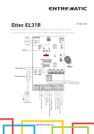
4. BRANCHEMENTS ÉLECTRIQUES
4.1 Branchements armoire de commande électronique / moteur / dispositifs de sécurité
ǩ6XUODȌJXUHVRQWUHSRUW«VOHVVFK«PDV«OHFWULTXHVGHVF¤EODJHVHWOHXUSRVLWLRQQHPHQWVXUODSRUWHbFKDTXHF¤EODJH
est identifié par un code apposé sur une étiquette adhésive.
4.2 Cellules photoélectriques de sécurité
ǩ(IIHFWXHUOHVUDFFRUGHPHQWVFRPPHLQGLTX«VXUODfig. 11).
ǩ(IIHFWXHUOHVEUDQFKHPHQWVGDQVO
DUPRLUHGHFRPPDQGH«OHFWURQLTXHFRPPHLQGLTX«VXUOHVFK«PD«OHFWULTXHpar. 5.3)
11
SB
M
E
8553B
8568
M
F
M
E
8562
8638
OFF
ON
8553A
Tx
8553B
Rx
Dimensionner correctement la section des conducteurs de ligne, en tenant compte de l'absorption indiquée et de la
longueur et de la pose des câbles.
-5-
0DT850 2015-05-08
5. ARMOIRE DE COMMANDE ÉLECTRONIQUE
5.1 ALIMENTATION ET PROTECTION
F1
F2
Si3 Si4
Si1 Si212V
F3
T1 T2 T3
PE
24 V
4
7
6
9 11 13 15 17 19 21 23 25 27 29 31
8 10 12 14 16 18 20 22 24 26 28 30 32
41 43 45 51 54
N N
L
42 44 46 53 53
Bleu
Noir
ØV
N
Bleu
2
5
Noir
3
Jaune-Vert
1
X1
L1 L1
111
112
113
211
PE
212
L
N
311
312
L
N
313
L
N
230V AC
FUSIBLES
ID
Valeurs
F1
T 250mA - L 250V
F2
T 500mA - L 250V
F3
T 3.15A - 230V
0DT850 2015-05-08
-6-
FR
5.2 RACCORDEMENTS MOTEUR ET ENCODEUR
Si3 Si4
Si1 Si212V
T1 T2 T3
PE
24 V
1
3
2
5
4
7
6
9 11 13 15 17 19 21 23 25 27 29 31
8 10 12 14 16 18 20 22 24 26 28 30 32
X1
L1 L1
41 43 45 51 54
N N
42 44 46 52 53
ØV
111
112
41 43 45
113
Porte ouverte
211
NO C NC
42 44 46
212
Porte fermée
311
NO C NC
312
L
N
313
Blanc
Jaune
Vert
Marron
Écran
Noir U/L1
Noir V/L2
Noir W/L3
Jaune/Vert
Noir
Blanc
Contacts libres max. 230V - 3A
LAMP
E
M
113
LK
N
SORTIES
RÉF.
Sortie
Valeur
M
UWV
M
3~
Description
230 V~ / 10 A
Moteur triphasé
LK
230 V = 0,2 A
Solénoïde frein de stationnement
LAMP
230 V
Clignotant (option)
ENTRÉES
RÉF.
Sortie
Description
E
E
Encodeur absolu
-7-
0DT850 2015-05-08
5.3 CONNEXIONS ENTRÉES
Si4
Si1 Si212V
T1 T2 T3
PE
24 V
1
3
2
5
4
7
6
9 11 13 15 17 19 21 23 25 27 29 31
8 10 12 14 16 18 20 22 24 26 28 30 32
X1
L1 L1
41 43 45 51 54
N N
L
42 44 46 52 53
N
ØV
111
112
113
211
1
212
7
5
2
6
8
311
312
L
N
Blanc
Rouge
Marron
Noir
Bleu
Fermeture
Ouverture
Arrêt
313
Commandes
externes
8562
Bleu
Noir
Bleu
Marron
Noir
Blanc
Rouge
8638
8568
Bleu
Noir
8553A
4 3
Bleu
Marron
Bleu
Marron
Noir
8553B
11 28
SB
12 11 28
Tx
Rx
DISPOSITIFS DE SÉCURITÉ 1-2 (NF) Arrêt externe
Contact
Description
3
4
N.F
Contact micro sécurité déverrouillage actionnement manuel
11
12
N.F
Cellule photoélectrique de sécurité
COMMANDES
Contact
Description
5
6
N.O.
Commande d'ouverture
7
8
N.O.
Commande de fermeture
0DT850 2015-05-08
-8-
FR
5.4 CONNEXION ET SYNCHRONISATION GOPAV
Si4
Si1 Si212V
T1 T2
8.2 kΩ
24 V
1
3
2
5
4
7
6
9 11 13 15 17 19 21 23 25 27 29 31
8 10 12 14 16 18 20 22 24 26 28 30 32
41 43 45 51 54
42 44 46 52 53
Accéder au dispositif GOPAVT en enlevant la
plaque latérale (B)
Attention : retirer la batterie de
l'unité mobile avant de procéder à la
configuration.
ØV
Alimenter l'unité fixe GOPAVR, normalement
les LED W clignoteront et le contact OUT1 sera
ouvert :
ƒ insérer la batterie de l'unité mobile GOPAVT
dans son logement, toutes les LED présentes
VXUO
XQLW«PRELOHFOLJQRWHURQWb
ƒ appuyer sur la touche (A) de l'unité fixe
GOPAVR : la LED W de l'unité fixe s'allumera
HWOD/('2&GHO
XQLW«PRELOHFOLJQRWHUDb
ƒ appuyer sur la touche (A) de l'unité mobile
GOPAVT, les LED de l'unité mobile et de
O
XQLW«Ȍ[HV
«WHLQGURQWb
ƒ vérifier la configuration correcte en activant le
bourrelet sensible et en contrôlant l'allumage de
la LED W sur l'unité fixe GOPAVR et de la LED IN.
A
IN1
GOPAVR
OUT1
SC
OC
W
0 1
B
GOPAVT
IN2
IN1
SC
OC
A
-9-
0DT850 2015-05-08
6. RÉGLAGES ET MISE EN MARCHE
6.1 BOÎTIER DE COMMANDE
Active la manœuvre d'ouverture.
Active la manœuvre de fermeture.
ON
S1
Active et désactive la fonction STOP.
Bouton d'arrêt d'urgence
Interrupteur général
OFF
ON
6.2 RÉGLAGE DES FINS DE COURSE
COMMANDE
OFF
FONCTION
Interrupteur général
Couper l'alimentation
Mettre le dip-switch S1 sur ON
Activation programmation paramètres
Interrupteur général
Mettre sous tension
Appuyer sur le bouton d'Arrêt d'Urgence
Activation entrée paramètres
ÉCRAN
ON
S1
ON
Bouton « Ouvrir » ou « Fermer » Recherche
des paramètres à définir
Rechercher le P.210 :
N.B. : tous les paramètres ne sont pas réglage fin de course
visibles
Appuyer sur le bouton « Stop » impulsion courte Afficher contenu paramètre
Augmenter la valeur paramétrée
Appuyer sur le bouton « Ouvrir »
Les points clignotent
Enregistrer la nouvelle valeur paramétrée
Appuyer sur le bouton « Stop » impulsion
Appuyer et maintenir enfoncé jusqu'à ce que les points
longue
clignotants s'éteignent
Appuyer sur le bouton « Stop » impulsion courte Retour à l'affichage des paramètres
Relâcher le bouton d'Arrêt d'Urgence
Accès au mode de réglage fin de course
Appuyer sur le bouton « Stop » impulsion courte Réglage fin de course en fermeture admis
3
3
3
>$O
( (9
&RQWU¶OHUOHVHQVGHURWDWLRQGXPRWHXUǤRXYULUǥǥIHUPHUǥbV
LOQ
HVWSDVFRUUHFWDFF«GHUDXSDUDPªWUH3 et modifier le sens de
rotation en changeant la valeur de à Appuyer sur le bouton « Fermer »
Commande de fermeture à « action maintenue »
jusqu'à la position de porte fermée
Appuyer sur le bouton « Stop » impulsion longue Enregistrer la position de « porte fermée »
Le système lance automatiquement
Réglage fin de course en ouverture admis
Appuyer sur le bouton « Ouvrir »
Commande d'ouverture à « action maintenue » jusqu'à
la position de porte ouverte
Appuyer sur le bouton « Stop » impulsion longue Enregistrer la position de « porte ouverte »
Le système lance automatiquement
Réglage fin de course intermédiaire admis
Appuyer sur le bouton « Fermer »
Commande de fermeture à « action maintenue »
jusqu'à la position intermédiaire
Appuyer sur le bouton « Stop » impulsion longue Enregistrer la position intermédiaire
0DT850 2015-05-08
- 10 -
( (9
( (9
( (R
( (R
( (R
( (,
( (,
( (,
FR
6.3 RÉGLAGE FIN DE LA POSITION DE FERMETURE
COMMANDE
OFF
FONCTION
Interrupteur général
Couper l'alimentation
Mettre le dip-switch S1 sur ON
Activation programmation paramètres
Interrupteur général
Mettre sous tension
Appuyer sur le bouton d'Arrêt d'Urgence
Activation entrée paramètres
ÉCRAN
ON
S1
ON
Bouton « Ouvrir » ou « Fermer » Recherche Rechercher le P.221 :
des paramètres à définir
réglage fin de la position de fermeture
3
3
Appuyer sur le bouton « Stop » impulsion courte Afficher contenu paramètre
Le correcteur + arrête la fermeture plus en haut et le
Bouton « Ouvrir » (vers +) ou « Fermer » (vers correcteur - arrête la fermeture plus en bas
-) pour régler la correction de hauteur
Par ex. - 3, le correcteur déplacera le point de
fermeture vers le sol
Enregistrer la nouvelle valeur paramétrée
Appuyer sur le bouton « Stop » impulsion longue Appuyer et maintenir enfoncé jusqu'à ce que les points
clignotants s'éteignent
Appuyer sur le bouton « Stop » impulsion courte Retour à l'affichage des paramètres
Relâcher le bouton d'Arrêt d'Urgence
Accès au mode de fonctionnement normal
Ouvrir et fermer la porte
Vérifier le point d'ouverture correct
*
3
6.4 RÉGLAGE FIN DE LA POSITION D'OUVERTURE
COMMANDE
OFF
FONCTION
Interrupteur général
Couper l'alimentation
Mettre le dip-switch S1 sur ON
Activation programmation paramètres
Interrupteur général
Mettre sous tension
Appuyer sur le bouton d'Arrêt d'Urgence
Activation entrée paramètres
ÉCRAN
ON
S1
ON
Bouton « Ouvrir » ou « Fermer » Recherche Rechercher le P.231 : réglage fin de la position de
des paramètres à définir
fermeture
Appuyer sur le bouton « Stop » impulsion courte Afficher contenu paramètre
Le correcteur + arrête l'ouverture plus en haut et le
Bouton « Ouvrir » (vers +) ou « Fermer » (vers correcteur - arrête l'ouverture plus en bas
-) pour régler la correction de hauteur
Par ex. + 3, le correcteur déplacera le point d'ouverture
vers le haut
Enregistrer la nouvelle valeur paramétrée
Appuyer sur le bouton « Stop » impulsion longue Appuyer et maintenir enfoncé jusqu'à ce que les points
clignotants s'éteignent
Appuyer sur le bouton « Stop » impulsion courte Retour à l'affichage des paramètres
Relâcher le bouton d'Arrêt d'Urgence
Accès au mode de fonctionnement normal
Ouvrir et fermer la porte
Vérifier le point d'ouverture correct
- 11 -
3
3
*
3
0DT850 2015-05-08
6.5 PROGRAMMATION DU TEMPS DE FERMETURE
COMMANDE
Appuyer sur le bouton d'Arrêt d'Urgence
FONCTION
Activation entrée paramètres
Bouton « Ouvrir » ou « Fermer » Recherche Rechercher le P.010 :
des paramètres à définir
Réglage du temps de fermeture
ÉCRAN
3
3
Appuyer sur le bouton « Stop » impulsion courte Afficher contenu paramètre (valeur par défaut)
Augmenter le temps de fermeture
Appuyer sur le bouton « Ouvrir »
Si la valeur est modifiée, les points décimaux
commenceront à clignoter.
Diminuer le temps de fermeture
Appuyer sur le bouton « Fermer »
Si la valeur est modifiée, les points décimaux
commenceront à clignoter.
Enregistrer la nouvelle valeur paramétrée
Appuyer sur le bouton « Stop » impulsion longue Appuyer et maintenir enfoncé jusqu'à ce que les points
clignotants s'éteignent
Permet d'annuler le réglage des paramètres.
Appuyer sur le bouton « Stop » impulsion courte
Sera rétablie la valeur par défaut
Relâcher le bouton d'Arrêt d'Urgence
*
*
Accès au mode de fonctionnement normal
7. ANOMALIES ET SOLUTIONS
7.1 FONCTIONS
P.
Plage (unité)
000
(cycles)
010
(s) 0….200
011
(s) 0….200
020
(ms) 0….1000
025
(s) 0….20
P
100
101
102
Plage (unité)
(Hz) 30…200
(A) 0…9,9
( % ) 40…100
103
(V) 100…500
130
0...1
P
210
P
Plage (unité)
0….5
Plage (unité)
221
(Ink) ± 125
231
(Ink) ± 60
0DT850 2015-05-08
Fonctions de la porte
Affichage du nombre de cycles de la porte
Affichage : 1234567 → 1234. ź-taper .567
Affichage :
67 → 67
Temps de maintien position ouverte (position de fin de course supérieure – Eo)
0 = dispositif de fermeture automatique désactivé.
Temps de maintien position ouverte (arrêt intermédiaire - E1)
0 : fermeture automatique désactivée
Temps de préavis avant l'ouverture
Le mouvement d'ouverture ralentit après la réception de la commande OPEN
(ouverture) d'une période de temps spécifiée dans ce paramètre.
Faire attention à l'unité. Pour paramétrer un préavis de 4 secondes, modifier le
paramètre P.020 à 400
Temps de préavis avant la fermeture
Le mouvement de fermeture ralentit après la réception de la commande CLOSE
(fermeture) ou à l'expiration du temps de fermeture automatique (fermeture forcée)
d'une période de temps spécifiée dans ce paramètre.
Défaut
Données nominales du moteur
Fréquence nominale du moteur (voir l'étiquette, note : Y/Δ)
Courant nominal du moteur (voir l'étiquette, note : Y/Δ)
Facteur de puissance cosM (voir l'étiquette : cos M: 0.63 →63)
Tension nominale du moteur (voir l'étiquette, note : Y/Δ). La courbe des caractéristiques
du moteur est calculée automatiquement sur la fréquence et la tension nominales.
Champ de rotation du moteur
0 : Rotation à droite 1 : Rotation à gauche
Défaut
-1
-1
-1
Indication des positions de fin de course avec les arrêts électroniques
Sélection de la position du réglage en mode « à action maintenue » (« teach in ») :
0 : non → Aucune/Annuler
1 : Eu → Interrupteur de fin de course inférieure et supérieure (arrêt intermédiaire :
voir P244)
2 : Eo → Interrupteur de fin de course supérieure (arrêt intermédiaire : voir P244)
3 : uo → Interrupteur de fin de course supérieure et inférieure
4 : E1 → Interrupteur de fin de course intermédiaire (P244 est ignoré)
5 : al → (all) Interrupteur de fin de course inférieure, supérieure et intermédiaire (P244)
Défaut
Correction des positions de fin de course avec les arrêts électroniques
Valeur de correction pour les fins de course inférieures (paramétrée sur 0 uniquement
avec un nouveau réglage).
Valeur de correction pour les fins de course supérieures (paramétrée sur 0 uniquement
avec un nouveau réglage).
Défaut
- 12 -
4
10
0
0
-1
1
O
O
O
FR
P
910
920
Plage (unité)
0…15
Eb1
Eb2
Eb3
Eb4
Ebcl
Eb
925
930
940
{s} 0….120,0
{V}
980
0….2
Diagnostic
Sélection du mode d'affichage (demandée via le bouton ARRÊT ou durant le mouvement du
moteur)
0 : Séquence du contrôleur (mode automatique)
1 : {Hz} Fréquence du champ tournant courant
2 : {A} Courant du moteur actuel (> 1A)
3 : {V} Courant du moteur actuel
4 : {A} Courant du branchement actuel (courant réel)
5 : {V} Tension du raccordement
6 : {°C} Température finale en °C
7 : {°F} Température finale en °F
8 : Dernier temps de fonctionnement mesuré (1/10 à 99,9 secondes, 1/1 de 100 secondes)
S'applique uniquement aux fins de course électroniques
9 : [Ink] progrès de la position actuelle
10 : [Ink] position de référence actuelle
11 : [dig] valeur du canal 1 de l'encodeur absolu actuelle
12 : [dig] valeur du canal 2 de l'encodeur absolu actuelle
13 : [dig] tension de référence actuelle (2,5 V)
14 : Température dans la structure en (°C)
15 : Température dans la structure en (°F)
Affichage des messages d'erreur/dysfonctionnements
Ouvrir en appuyant de nouveau sur la touche d'arrêt
Activer/Désactiver au moyen de la touche d'ouverture/fermeture
Fermer en appuyant de nouveau sur la touche d'arrêt
Terminer l'opération en annulant « EB- »
ǩ(EǵPHVVDJHVG
HUUHXUSOXVU«FHQWHRX (U
ǩ(EǵPHVVDJHVG
HUUHXU
(U
ǩ(EǵPHVVDJHVG
HUUHXU
(U
ǩ(EǵPHVVDJHVG
HUUHXU
(U
ǩ(EFOǵ«OLPLQHUWRXWHVOHVHUUHXUVHQP«PRLUH
ǩ(Eǵ$QQXOHU
(Afficher noEr : aucune erreur).
Affichage de la version logiciel
Temps de fonctionnement du moteur pendant le dernier mouvement de la porte
Affichage de la tension d'alimentation secteur
Mode de maintenance
0 : Automatique (ouverture et fermeture en position de maintien)
1 : Action maintenue pour position fermée (mode manuel fermé/mode automatique ouvert)
2 : Action maintenue (mode manuel pour position ouverte et fermée)
b8UJHQFHDFWLRQPDLQWHQXHSRXUSRVLWLRQRXYHUWHHWIHUP«HbWRXWHVOHVHUUHXUVHWOHV
protections sont ignorées)
Défaut
O
Eb 1
0
7.2 VUE D'ENSEMBLE DES MESSAGES
F.000
Position incorrecte dans la partie
supérieure de la porte.
F.005
Position incorrecte dans la partie
inférieure de la porte.
F.020
F.030
F.031
F.043
Positions de fin de course incorrectes
- Valeur du paramètre trop basse pour l'arrêt d'urgence de la fin de course
supérieure.
- Intervalle (bande) de la fin de course supérieure trop petit.
- Valeur du paramètre trop basse pour l'arrêt d'urgence de la fin de course
inférieure.
- Intervalle (bande) de la fin de course inférieure trop petit.
- Frein mécanique défectueux ou mal réglé.
Imprécisions relatives aux mouvements de la porte
- Le temps de fonctionnement actuel du moteur a dépassé la valeur maximale
Dépassement du temps de
définie. La porte pourrait fonctionner anormalement ou se bloquer.
fonctionnement (durant l'ouverture,
la fermeture ou l'utilisation « à action - Une fin de course ne s'est pas mise en marche à l'activation des fins de
course mécaniques.
maintenue »)
- La porte ou le moteur sont bloqués
- Performances insuffisantes pour le couple nécessaire
Erreurs de traction (la position
- Vitesse insuffisante
prédéterminée pour la porte n'est pas
- Fixation insuffisante à l'arbre du détecteur de valeurs absolues ou du
atteinte)
détecteur différentiel
- Utilisation erronée du système de positionnement (P.205).
- Lorsque l'on utilise le détecteur différentiel : Les canaux A et B ont été échangés
- Le sens de rotation du moteur a été modifié en phase de réglage
Le sens de rotation enregistré n'est
- Abaissement excessif au démarrage, activation des freins à l'avance ou
pas celui prévu
couple insuffisant. Si nécessaire, régler la tension.
Erreur dans la fin de course avant de la - La fin de course avant de la barre lumineuse se trouve dans la position de
barre lumineuse
fin de course centrale et supérieure.
- 13 -
0DT850 2015-05-08
F.050
F.051
F.052
F.090
Message d'erreur du détecteur différentiel
- L'arrêt de référence est activé à chaque fois (défectueux).
La position de l'arrêt de référence
- L'arrêt de référence est activé trop loin de la référence sélectionnée.
est en dehors de la plage acceptable
- L'arrêt de référence est activé près de la courroie de la fin de course.
pendant la synchronisation cyclique.
- P270 et P280 sont tous les deux sur l'arrêt de référence.
- L'arrêt de référence est positionné près de la courroie de la fin de course.
La position de l'arrêt de référence est
- L'arrêt de référence est positionné à plus de 15 % EO.
en dehors de la plage acceptable.
- L'arrêt de référence est défectueux.
- Lors de la synchronisation après l'activation, l'arrêt de référence n'est pas
L'arrêt de référence n'est pas reconnu. reconnu dans la plage de 20 % EO.
- L'arrêt de référence n'est pas reconnu dans la position de fin de course.
Paramètre non défini
Les paramètres n'ont pas été attribués Les paramètres de base (P.205 et de P.100 à P.103) des commandes TST FUE
à la commande.
n'ont pas encore été fixés.
F.201
Bouton « Arrêt d'urgence » interne
activé ou Watchdog
(surveillance de l'ordinateur).
F.211
F.212
Arrêt d'urgence externe 1 activé.
Arrêt d'urgence externe 2 activé.
Erreurs dans la chaîne de sécurité
L'arrêt d'urgence a été interrompu sur l'entrée de l'« arrêt d'urgence
interne » sans que le mode de paramétrage Interne ait été sélectionné ou
Contrôles EEPROM défectueux. Appuyer sur le bouton d'arrêt pour plus
d'informations sur la cause
L'arrêt d'urgence a été interrompu sur l'entrée 1. (bornes 1 et 2)
L'arrêt d'urgence a été interrompu sur l'entrée 2. (bornes 3 et 4)
Erreurs dans la chaîne de sécurité
A été relevé un court-circuit sur
F.360
l'entrée de la protection
Erreur de redondance avec courtF.362
circuit
F.363
F.364
F.365
F.369
F.374
F.385
F.400
F.410
F.420
F.430
F.435
F.440
F.510
A été relevé un court-circuit sur les protections avec contact normalement
fermé
L'un des canaux de traitement pour la détection du court-circuit réagit
différemment de l'autre canal. → Carte contrôleur défectueuse
Câble de raccordement défectueux ou non connecté
Interruption sur l'entrée de la
Résistance de terminaison incorrecte ou absente
protection
Pontet J600 non réglé correctement
À la demande du test, le détecteur d'obstacles n'a pas été activé comme prévu.
Échec du test du détecteur d'obstacles
L'heure de la demande du test et celle de l'exécution du test ne coïncident pas
L'un des canaux de traitement pour la détection de l'interruption réagit
Erreur de redondance avec interruption différemment de l'autre canal.
→ Carte contrôleur défectueuse
Paramètres détecteur d'obstacles
Détecteur interne d'obstacles connecté mais désactivé
interne non réglés correctement
Interrupteur de pré-fin de course du détecteur d'obstacles mal réglé ou
défectueux
Échec du test bourrelet sensible
Module de traitement défectueux
Détecteur d'obstacles défectueux
Lorsque le détecteur d'obstacles se déclenche, l'interrupteur de pré-fin de
Erreur dans l'interrupteur de pré-fin
course pour la désactivation ou l'inversion du détecteur d'obstacles reste actif
de course du détecteur d'obstacles
même en position de fin de course supérieure.
ǩ%UXLWH[FHVVLIVXUODWHQVLRQG
DOLPHQWDWLRQ
A été relevé un rétablissement du
ǩ:DWFKGRJLQWHUQHG«FOHQFK«
matériel du contrôleur
ǩ(UUHXU5$0
ǩ2QW«W«SDUDP«WU«HVGHVGRQQ«HVPRWHXUHUURQ«HV33
ǩ$XJPHQWDWLRQGHWHQVLRQQRQU«JO«HVXUDOLPHQWDWLRQSDUDP«WU«H3RX3
Surintensité (courant du moteur ou
ǩ'LPHQVLRQQHPHQWGXPRWHXUGHODSRUWHLQFRUUHFW
circuit intermédiaire).
ǩ/HYLHUVSRUWH
ǩ,QWHUUXSWHXUIUHLQDYHFLQWHUI«UHQFHVG«IHFWXHX[DEVHQW
ǩ/DWHQVLRQG
DOLPHQWDWLRQHVWWURS«OHY«H
Surtension du circuit intermédiaire
ǩ/HPRWHXUUHVWLWXHWURSG
«QHUJLHHQPRGHJ«Q«UDWHXULOHVWLPSRVVLEOHGH
Limite 1.
réduire suffisamment l'énergie de mouvement de la porte
ǩ&KDUJHGDQVOHVSKDVHVȌQDOHVRXVXUO
LQWHUUXSWHXUIUHLQWURS«OHY«H
La température de l'unité de
refroidissement a dépassé la limite de ǩ7HPS«UDWXUHDPELDQWHWURSEDVVHSRXUIDLUHIRQFWLRQQHUOHFRQWU¶OHXU
ǩ)U«TXHQFHG
KRUORJHGHODSKDVHȌQDOHWURS«OHY«H3DUDPªWUH3
la plage de fonctionnement 1.
Erreur : la température interne
ǩ&KDUJHVXUOHFRQYHUWLVVHXUGHIU«TXHQFHFLUFXLWWURS«OHY«H
dépasse 75 °C.
ǩ$UPRLUHGHFRPPDQGHGXFRQWU¶OHXUQRQVXIȌVDPPHQWUHIURLGLH
ǩ6XUDOLPHQWDWLRQQRQU«JO«H
Surtension du circuit intermédiaire
ǩ'LPHQVLRQQHPHQWGXPRWHXUGHODSRUWHLQFRUUHFW
Limite 1.
ǩ/HYLHUVSRUWH
ǩ2QW«W«SDUDP«WU«HVGHVGRQQ«HVPRWHXUHUURQ«HV33
ǩ$XJPHQWDWLRQGHWHQVLRQQRQU«JO«HVXUDOLPHQWDWLRQSDUDP«WU«H3RX3
Surintensité du moteur/circuit
ǩ'LPHQVLRQQHPHQWGXPRWHXUGHODSRUWHLQFRUUHFW
intermédiaire Limite 2.
ǩ/HYLHUVSRUWH
0DT850 2015-05-08
- 14 -
F.511
Problème avec injection de courant
pour freiner
F.515
La fonction de protection du moteur a
relevé une surintensité
F.519
La puce de l'actionneur IGBT a relevé
une surintensité
F.520
Surtension du circuit intermédiaire
Limite 2.
F.521
Surtension du circuit intermédiaire
F.524
Ext. Pas d'alimentation externe à 24 V
ou alimentation trop basse.
F.530
F.535
F.540
F.700
F.720
FR
ǩ&RQWU¶OHUOHVSDUDPªWUHVGH3¢3
ǩ(VVD\HUGHU«GXLUH3HW3
ǩ5«JODJHFRXUEHPRWHXUHUURQ«FRXUDQWQRPLQDOGXPRWHXU3
ǩ6XUDOLPHQWDWLRQWURS«OHY«H3RX3
ǩ0RWHXUQRQGLPHQVLRQQ«FRUUHFWHPHQW
ǩ&RXUWFLUFXLWRXHUUHXUGHPDVVHDX[ERUQHVGXPRWHXU
ǩ5«JODJHFRXUDQWQRPLQDOGXPRWHXUHUURQ«3
ǩ6XUDOLPHQWDWLRQWURS«OHY«H3RX3
ǩ0RWHXUQRQGLPHQVLRQQ«FRUUHFWHPHQW
ǩ'«URXOHPHQWPRWHXUG«IHFWXHX[
ǩ,QWHUUXSWLRQWHPSRUDLUHGXFLUFXLWG
DUU¬WG
XUJHQFH
ǩ,QWHUUXSWHXUIUHLQDYHFLQWHUI«UHQFHVG«IHFWXHX[DEVHQW
ǩ/DWHQVLRQG
DOLPHQWDWLRQHVWWURS«OHY«H
ǩ/HPRWHXUUHVWLWXHWURSG
«QHUJLHHQPRGHJ«Q«UDWHXULOHVWLPSRVVLEOHGH
réduire suffisamment l'énergie de mouvement de la porte
ǩ$OLPHQWDWLRQG
HQWU«HWURSEDVVHKDELWXHOOHPHQWHQFRQGLWLRQGHFKDUJH
ǩ&KDUJHGDQVOHVSKDVHVȌQDOHVRXVXUO
LQWHUUXSWHXUIUHLQWURS«OHY«H
ǩ6XUFKDUJHVDQVFRXUWFLUFXLW
ǩ(QFDVGHFRXUWFLUFXLWVXUXQHWHQVLRQGH9OHFRQWU¶OHXUQ
DFF«OªUHSDV
et une lampe à luminescence V306 s'allume.
ǩ&KDUJHGDQVOHVSKDVHVȌQDOHVRXVXUO
LQWHUUXSWHXUIUHLQWURS«OHY«H
ǩ7HPS«UDWXUHDPELDQWHWURSIDLEOHSRXUIDLUHIRQFWLRQQHUOHFRQWU¶OHXU
ǩ)U«TXHQFHG
KRUORJHGHODSKDVHȌQDOHWURS«OHY«H3DUDPªWUH3
La température de l'unité de
refroidissement a dépassé la limite de
la plage de fonctionnement 1.
Erreur : la température interne dépasse
ǩ7HPS«UDWXUHLQWHUQHWURS«OHY«H
la température critique de 80 °C.
ǩ6XUDOLPHQWDWLRQQRQU«JO«H
Surtension du circuit intermédiaire
ǩ'LPHQVLRQQHPHQWGXPRWHXUGHODSRUWHLQFRUUHFW
Limite 2.
ǩ/HYLHUVSRUWH
Pour les interrupteurs de fin de course électroniques :
ǩ$SUªVDYRLUGHPDQG«O
DFWLYDWLRQGHVSDUDPªWUHVSU«G«ȌQLVSDUDPªWUHV
P.990), les paramètres du système de positionnement correspondant n'ont
pas été réglés.
Détection de la position erronée
ǩ/HU«JODJHQ
DSDV«W«WHUPLQ«RXHVWHUURQ«,OGRLW¬WUHU«S«W«
ǩ/RUVTXHO
DUU¬WLQWHUP«GLDLUHHVWDFWLY«FHWWHFRPPDQGHHVWLPSUREDEOH
ǩ6\QFKURQLVDWLRQQRQFRQFOXHRXLQWHUUXSWHXUGHU«I«UHQFHG«IHFWXHX[
ǩ/DSRVLWLRQG
DUU¬WLQWHUP«GLDLUHHVWLQI«ULHXUH¢ODYDOHXULQFU«PHQWLHOOH
minimale (25).
ǩ6\QFKURQLVDWLRQQRQFRQFOXH
ǩ/
LQWHUUXSWHXUGHU«I«UHQFHV«OHFWLRQQ«Q
DSDV«W«DWWHLQWRXHVWKRUV
tolérance
Erreur de synchronisation dans la
ǩ/HFRGHXULQFU«PHQWDOQHFRPSWHSDVRXODSRUWHHVWEORTX«H«JDOHPHQW
détection position avec encodeur
erreur de retard F.030)
ǩ2QW«W«LQYHUV«HVOHVHQWU«HVLQFU«PHQWDOHV,1HW,1«JDOHPHQWHUUHXU
de rotation F.031)
F.750
Erreur Transmission de protocole
F.751
Synchronisation FU <-> encodeur
absolu
F.752
Temps
de transmission protocole expiré
F.760
Position hors intervalle
F.761
La distance entre le canal 1 et le canal
2 n'est pas dans la plage autorisée.
F.762
Positions de fins de course
électroniques erronées
ǩ0DW«ULHOG«IHFWXHX[RXSU«VHQFHGHEUXLW«OHFWULTXHGDQVO
HQYLURQQHPHQW
ǩ0DW«ULHOG«IHFWXHX[RXSU«VHQFHGHEUXLW«OHFWULTXHGDQVO
HQYLURQQHPHQW
ǩOHFWURQLTXHGXSURFHVVHXUHQFRGHXUDEVROXG«IHFWXHXVH
ǩ&¤EOHLQWHUIDFHG«IHFWXHX[FDVV«
ǩOHFWURQLTXHGXSURFHVVHXUGHO
HQFRGHXUDEVROXG«IHFWXHXVH
ǩ0DW«ULHOG«IHFWXHX[RXSU«VHQFHGHEUXLW«OHFWULTXHGDQVO
HQYLURQQHPHQW
ǩ$FWLRQQHPHQWHQFRGHXUGHSRVLWLRQG«IHFWXHX[
ǩOHFWURQLTXHGHWUDLWHPHQWHQFRGHXUDEVROXG«IHFWXHXVH
ǩ0DW«ULHOG«IHFWXHX[RXSU«VHQFHGHEUXLW«OHFWULTXHGDQVO
HQYLURQQHPHQW
ǩ$FWLRQQHPHQWHQFRGHXUGHSRVLWLRQG«IHFWXHX[
ǩ0DW«ULHOG«IHFWXHX[RXSU«VHQFHGHEUXLW«OHFWULTXHGDQVO
HQYLURQQHPHQW
ǩ/
LQWHUUXSWHXUGHȌQGHFRXUVHVXS«ULHXUH(RRXO
LQWHUUXSWHXUGHȌQGH
course intermédiaire E1 a dépassé la plage de valeurs valide
ǩ&RQWU¶OHXUSDVHQFRUHLQLWLDOLV«
ǩ9DOHXUVGHSRVLWLRQGXUDQWOHU«JODJHTXLQHVRQWSDVFRUUHFWHVRXYDOHXUV
qui ne sont plus probables
- 15 -
0DT850 2015-05-08
7.3 ERREURS LIÉES AU SYSTÈME INTERNE F.9XX
Paramètre non défini
Cette catégorie prévoit des erreurs internes qui ne peuvent pas être résolues par l'utilisateur.
Si ces erreurs se produisent, contacter immédiatement le service clients.
7.3.1 MESSAGES D'INFORMATION
STOP
_Eu_
{Eu{
ZUF°
-Eo{Eo{
°AUF
-E1{E1{
FAIL
CALI/EICH
{NA{
NOTF
'Hd'
ParA
SYNC
'Au'
'Hc'
FUS
E.i.E.u.
E.i.E.o.
E.i.E.1.
S.y.E.u.
S.y.E.o.
S.y.E.1.
S.y.op
S.y.Cl
S.y.c{
Hd.cL
Hd.on
Hd.Eu
Hd.Eo
Hd.Ao
I.080
I.100
I.150
I.160
0DT850 2015-05-08
Messages généraux
État d'arrêt/rétablissement. Attendre l'instruction suivante.
Position de fin de course inférieure Eu
Position de fin de course inférieure bloquée → levage impossible (par exemple : porte bloquée)
Fermeture en cours
Position de fin de course supérieure Eo.
Position de fin de course supérieure bloquée → fermeture impossible (par exemple : détecteur d'obstacles).
Ouverture en cours.
Position de fin de course centrale E1 (position d'arrêt intermédiaire)
Position de fin de course centrale bloquée → fermeture impossible (par exemple : détecteur d'obstacles).
Erreur → n'est possible que la course à action maintenue, si possible avec ouverture automatique 0
Réglage → réglage des positions de fin de course quand est activé le mode « à action maintenue »
(pour encodeur absolu) → procédure de démarrage avec la touche ARRÊT.
Arrêt d'urgence → Aucune course n'est possible, chaîne de sécurité matériel interrompue.
Arrêt d'urgence → Course à action maintenue sans mesures de sécurité, etc.
Manuel → Mode « à action maintenue ».
Paramétrage
Synchronisation (codeur incrémental/fin de course → pos. inconnue).
Automatique → indique le passage de l'état « manuel » à « automatique ».
Semi-automatique → indique la transition de l'état « manuel » à « semi-automatique ».
Affichage initial après le démarrage. (Démarrage et auto-test)
Messages d'état pendant le réglage
Réglage de la position de fin de course inférieure requis (en mode « à action maintenue »).
Réglage de la position de fin de course supérieure requis (en mode « à action maintenue »).
Réglage de la position intermédiaire E1 (en mode « à action maintenue »).
Messages d'état pendant la synchronisation
Synchronisation de la position de fin de course inférieure requise
(mode « à action maintenue » ou en attente de démarrage)
Synchronisation de la position de fin de course supérieure requise
(mode « à action maintenue » ou en attente de démarrage)
Synchronisation de la position intermédiaire E1 (en mode « à action maintenue »).
Ouverture automatique au contact mécanique, suivie de la synchronisation automatique de la position
de fin de course supérieure
Fermeture automatique avec surveillance des dispositifs de sécurité pour le contact mécanique, suivie
de la synchronisation automatique de la position de fin de course inférieure
La fermeture automatique est bloquée, selon la condition A
Messages d'état lors de l'utilisation « à action maintenue »
Utilisation « à action maintenue » durant la fermeture (touche à membrane : FERMER).
Utilisation « à action maintenue » durant l'ouverture (touche à membrane : OUVRIR).
Position de fin de course inférieure à la plage. Ne sera plus autorisée l'utilisation « à action
maintenue » pendant la fermeture.
Position de fin de course supérieure à la plage. Ne sera plus autorisée l'utilisation « à action
maintenue » pendant l'ouverture.
Non compris dans la plage autorisée pour la position Eo (ne sera plus autorisée l'utilisation « à action
maintenue » durant l'ouverture).
Messages d'information lors de l'utilisation automatique
Entretien requis à court terme/compteur de maintenance presque à zéro.
La vitesse d'atteinte de la position de fin de course supérieure est trop élevée.
La vitesse d'atteinte de la position de fin de course inférieure est trop élevée.
Porte FERMÉE encore active
- 16 -
I.170
I.199
I.200
I.201
I.202
I.203
I.205
I.210
I.211
I.310
I.500
I.501
I.502
I.505
I.506
I.507
I.510
I.515
I.555
FR
Ouverture forcée en cours.
Cycle de la porte improbable (réinitialisation → paramètres).
Position de référence correcte ou reconnue (après le réglage).
Position de référence réinitialisée.
Position de référence manquante.
Position de référence erronée.
Synchronisation.
Interrupteur de pré-fin de course supérieure improbable.
Interrupteur de pré-fin de course inférieure improbable.
Utilisation de la commande d'ouverture sur la Porte 2 en cours (système de verrouillage pneumatique AIRLOCK)
Correction de l'interrupteur de fin de course supérieure en cours
Interrupteur de fin de course supérieure correct
Bande de l'interrupteur de fin de course supérieure correcte
Correction de l'interrupteur de fin de course inférieure en cours.
Interrupteur de pré-fin de course inférieure correct
Bande de l'interrupteur de fin de course inférieure correcte
Correction interrupteur de fin de course terminée
Le contrôleur règle le mode automatique de « teach-in » des interrupteurs de fin de course
Correction des interrupteurs de fin de course en cours
noEr
Er-Prog
Messages d'information durant le paramétrage
Erreur de mémoire. Une erreur ne sera pas enregistrée.
Erreur de mémoire. Impossible de trouver le message correspondant à l'erreur.
Message de programmation lorsque le paramètre d'origine ou le réglage par défaut est exécuté.
E.000
E.050
E.090
E.101
E.102
E.103
E.104
E.105
E.106
E.107
E.108
E.109
E.110
E.132
Entrées générales
Touche à membrane d'ouverture.
Touche à membrane d'arrêt.
Touche à membrane de fermeture.
Entrée 1 / borne 6
Entrée 2 / borne 8
Entrée 3 / borne 10
Entrée 4 / borne 12
Entrée 5 / borne 14
Entrée 6 / borne 16
Entrée 7 / borne 18
Entrée 8 / borne 20
Entrée 9 / borne 22
Entrée 10 / borne 24
Contrôler que la valeur de PA32 est égale à 0.
E.201
E.211
E.212
Plage de sécurité/urgence
Bouton d'arrêt d'urgence interne activé.
Arrêt d'urgence externe 1 activé.
Arrêt d'urgence externe 2 activé.
E.360
E.363
E.370
E.373
E.379
Aspects généraux du détecteur
Activation du détecteur d'obstacles interne.
Erreur dans le détecteur d'obstacles interne.
Activation du détecteur d'obstacles externe.
Erreur dans le détecteur d'obstacles externe.
Détecteur d'obstacles externe activé mais pas encore inséré.
E.501
E.502
Module de plug-in processeur circuit d'induction
Détecteur canal 1
Détecteur canal 2
E.900
Entrées internes
Signal d'erreur du module drive.
- 17 -
0DT850 2015-05-08
CARACTÉRISTIQUES DE L'UTILISATION
Classe d'usage : 5 (minimum de 5 années d'utilisation avec 600 cycles par jour)
Usage : TRÈS INTENSIF (pour des entrées de type industriel et commercial à usage très intensif)
ǩ/D FODVVH G
XVDJH OHV WHPSV G
XWLOLVDWLRQ HW OH QRPEUH GH F\FOHV FRQV«FXWLIV VRQW GRQQ«V ¢ WLWUH LQGLFDWLI ,OV RQW «W«
statistiquement relevés dans des conditions d'utilisation moyenne et peuvent varier d'une application à l'autre. Ils se
réfèrent à une période au cours de laquelle le produit fonctionne sans exiger un entretien extraordinaire particulier.
ǩ&KDTXHHQWU«HDXWRPDWLTXHSU«VHQWHGHV«O«PHQWVYDULDEOHVFRPPHbOHVIURWWHPHQWVOHV«TXLOLEUDJHVHWOHVFRQGLWLRQV
ambiantes, qui peuvent modifier sensiblement la durée et la qualité du fonctionnement de l'entrée automatique ou d'une
partie de ses composants (parmi lesquels les automatismes). Il est à la charge de l'installateur d'adopter des coefficients
de sécurité adaptés à l'installation spécifique.
DÉCLARATION DE CONFORMITÉ
Nous soussignés :
Entrematic Group AB
Lodjursgatan 10
SE-261 44 Landskrona
Suède
déclarons sous notre responsabilité que le produit avec la dénomination/la description :
ALIMAX
Porte rapide à enroulement non contrebalancée
caractérisée par les niveaux de performance indiqués dans la Déclaration de Performance et sur l'étiquette du produit, et à
motorisation électrique comme indiqué dans le manuel d'installation qui l'accompagne, est conforme aux directives suivantes :
2006/42/CE Directive Machines (DM)
2004/108/CE Directive Compatibilité Électromagnétique (DCEM)
Normes européennes harmonisées appliquées :
EN 13241-1 EN 61000-6-2 EN 61000-6-3 EN 60335-1 EN 60204-1
Autres normes ou spécifications techniques appliquées :
EN 60335-2-103
L'organisme notifié suivant (pour l'adresse complète contacter Entrematic Group AB) a délivré le Certificat d'examen de
type relatif au produit en objet :
CSI Spa Reg. - N° 0497
Certificat N° : 0005\DC\POR\13
Le procédé de fabrication assure la conformité du produit au dossier technique.
Le procédé de fabrication est régulièrement contrôlé par un tiers.
Responsable du dossier technique :
Marco Pietro Zini
E-mail : [email protected]
Entrematic Group AB
Lodjursgatan 10
SE-261 44 Landskrona
Suède
Lieu Date Signature Fonction
Landskrona
2013-07-01
0DT850 2015-05-08
Marco Pietro Zini
- 18 -
Président Entrance Automation
FR
INSTRUCTIONS D'UTILISATION ET D'ENTRETIEN
CONSIGNES GÉNÉRALES DE SÉCURITÉ
Le présent manuel fait partie intégrante et essentielle du produit et doit être remis à l'utilisateur. Il faut conserver
le présent document et le transmettre aux éventuels utilisateurs successifs de l’équipement. L’automatisme en
objet est une « porte à mouvement vertical » à destiner à l'usage pour lequel elle a été expressément conçue.
Toute autre utilisation doit être considérée comme non conforme et donc dangereuse.Entrematic Group AB décline
toute responsabilité pour les dommages résultant d'une utilisation non conforme, incorrecte ou déraisonnable.
PRÉCAUTIONS D'UTILISATION
ǩ1HSDVHQWUHUGDQVOHUD\RQG
DFWLRQGHODSRUWHORUVTX
HOOHHVWHQPRXYHPHQW
ǩ(Q FDV GH SDQQH RX GH G\VIRQFWLRQQHPHQW FRXSHU O
LQWHUUXSWHXU J«Q«UDO /HV RS«UDWLRQV G
HQWUHWLHQ GH
réglage et de réparation doivent uniquement être exécutées par un personnel formé et autorisé.
ǩ&KDTXHDXWRPDWLVPHHVWDFFRPSDJQ«G
XQmb0DQXHOG
LQVWDOODWLRQHWG
HQWUHWLHQb}GDQVOHTXHOȌJXUHHQWUHDXWUH
le plan d'entretien périodique et où il est recommandé, en particulier, de vérifier tous les dispositifs de sécurité.
BOUTONS-POUSSOIRS
ǩ2XYHUWXUHWRWDOHbRXYUHFRPSOªWHPHQWODSRUWH/HU«JODJHGHODFRXUVHVHIDLW¢O
DLGHG
XQPLFURLQWHUUXSWHXU
de fin de course.
ǩ6723bSURYRTXHO
DUU¬WLPP«GLDWGHODSRUWH
OPTION DS - MANŒUVRE MANUELLE
ǩ3RXUVRXOHYHUPDQXHOOHPHQWOHWDEOLHUHQFDVGHFRXSXUHGHFRXUDQWRXGHSDQQHVRXOHYHUOHWDEOLHUMXVTX
¢
la position de porte ouverte, comme illustré sur le schéma.
NETTOYAGE
Pour maintenir un bon niveau d'hygiène, il est conseillé de laver la porte tous les jours ou au besoin pour
éviter l'accumulation de saleté et le dépôt des substances traitées. Toutes les surfaces exposées peuvent être
nettoyées avec des détergents ordinaires disponibles dans le commerce tels que :
- Hypochlorite de sodium en solution diluée (25 %)
- Ammoniac en solution diluée (25 %)
- Détergents tensio-actifs, moussants et non moussants
La partie supérieure des substances traitées doit être couverte lors du passage à travers la porte.
1HSDVODLVVHUODWLJHGHFRPPDQGH
PDQXHOOHDFFURFKpHjODEDJXH
GXUDQWOHIRQFWLRQQHPHQWQRUPDO
GHODSRUWH8WLOLVHUOHVSDWWHVGH
¿[DWLRQDXPXU
ON
OFF
À DÉTACHER ET REMETTRE À L'UTILISATEUR
ǩ)HUPHWXUHbIHUPHFRPSOªWHPHQWODSRUWH/HU«JODJHGHODFRXUVHVHIDLW¢O
DLGHG
XQPLFURLQWHUUXSWHXUGH
fin de course.
Fermer
Ouvrir
Installateur :
Entrematic Group AB
Lodjursgatan 10
SE-261 44, Landskrona
Suède
www.ditecentrematic.com
- 19 -
0DT850 2015-05-08
8. MANUEL D'UTILISATION ET DE NETTOYAGE POUR ENVIRONNEMENTS ALIMENTAIRES
INDICATIONS GÉNÉRALES
La porte est destinée à être utilisée dans des locaux où sont préparées des denrées alimentaires selon le règlement (CE)
N° 852/2004 sur l'hygiène des denrées alimentaires.
Elle n'est pas prévue pour être utilisée comme porte extérieure. La porte n'est pas munie d'une isolation thermique en
mesure d'empêcher la formation de condensation entre les locaux qui présentent une forte différence de température.
Les substances préparées devront être couvertes pendant le passage éventuel par la porte.
NETTOYAGE
Pour préserver un niveau d'hygiène correct, il est conseillé de laver la porte aux fréquences reportées dans le tableau suivant.
Prévoir le nettoyage de la porte au moyen de dispositifs normalement utilisés dans les environnements industriels alimentaires.
1. Température max. de l'eau de lavage : 70°C
2. Outillage :
- utiliser un outillage à l'eau sans pression
- éviter l'emploi de brosses à poils durs qui risqueraient
d'abîmer la surface de la structure/tablier
- utiliser un outillage propre
3. Produits :
- détergents industriels mousseux et non mousseux
- hypochlorite de sodium en solution diluée (eau de Javel
25%)
- ammonium en solution diluée (ammoniac 25%)
4. Essuyage :
- torchons propres
- papier essuie-tout jetable
L'avertissement d'utiliser de l'eau ou de l'air sans pression vise à éviter la diffusion incontrôlée de saleté/résidus
d'aliments dans l'environnement ambiant
Fréquence conseillée
Quotidien
Hebdomadaire
Parties / composants
Méthodes
Surfaces extérieures à vue du Après le lavage, effectuer 4-5 manœuvres d'ouverture/fermeture de
tablier et de la structure.
la porte pour essorer l'eau présente sur le tablier.
Nettoyer l'intérieur du couvercle du caisson en passant un chiffon sur
le bord interne inférieur.
Enlever le bord inférieur des colonnes et essuyer à l'aide de chiffons
propres les plaques de fermeture de la poche des deux côtés.
Zone de coulissement du Nettoyer lorsque la porte est ouverte
tablier dans les colonnes.
Z o n e i n t e r n e s o u s le s Enlever les couvercles (1) pour le nettoyage et l'essuyage.
couvercles de la colonne (si Nettoyer les colliers (si présents) à l'aide d'une brosse.
présents).
Nettoyer les câbles sur toute leur longueur à l'aide d'un chiffon.
Tableau électronique
Après le lavage et le séchage extérieur du tableau, essuyer à l'aide de
chiffons propres le bord externe de la fermeture (2).
Intérieur des têtes sous les Enlever les couvercles (3) pour le nettoyage et l'essuyage.
Nettoyer la boîte de dérivation à l'aide d'une brosse à poils souples
couvercles.
Essuyer l'intérieur des têtes à l'aide de chiffons propres.
Essuyer la boîte de dérivation à l'aide de chiffons propres.
Intérieur du couvercle du Enlever le couvercle (4) pour le nettoyage et l'essuyage.
c a i s s o n e t d u ro u l e a u
enrouleur.
Les composants démontés pour le nettoyage doivent être remontés de manière à rétablir les conditions initiales.
4
2
3
1
0DT850 2015-05-08
- 20 -
FR
9. AMSES
+
01
X9
-
02
X9
88
1
2
90
X900
92
89
91
94
93
96
98
95
97
99
S
i3
i2
S
S
i4
V
12
1
3
5
K4
7
9
6
K5
K6
K7
8
11
13
10
15
12
17
14
19
16
21
18
23
20
25
22
27
24
29
26
31
Si3 Si4
K4 SIGNAL PORTE ACTIVE
+
Contact
88 90 92
X901
Si1 Si212V
89 91 93
X902
94 96 98
95 97 99
-
88
N.O
90
C
92
N.F
T1
1
3
2
5
4
7
6
9 11 13 15 17 19 21 23 25 27 29 31
8 10 12 14 16 18 20 22 24 26 28 30 32
41 43 45 51 54
42 44 46 52 53
9.1 CONNEXION DE LA FONCTION D'INTERVERROUILLAGE ET DE VERROUILLAGE PNEUMATIQUE
17
91 89
18
Porte A, message E107 (borne de connexion
18) : la porte A est bloquée en position FERMÉE.
Verrouillage
pneumatique
Interverrouillage
24
20
96
94
Porte A, message E108 (borne de connexion
20) : La porte A reçoit une commande
d'ouverture de la porte B
PORTE A
Porte A, message I130 (borne de connexion
94/96) : la porte A envoie une commande
d'ouverture à la porte B.
W
Bornes de raccordement 89/91 : la porte A
bloque la porte B en position FERMÉE.
W : Interrupteur de VERROUILLAGE ON/OFF
18
91 89
24
96
94
20
PORTE B
- 21 -
0DT850 2015-05-08
0DT850 2015-05-08
- 22 -
LISTE DES COMPOSANTS
PACKING LIST
Référence
Reference
Description
Description
Quantité
Quantity
A
Plaque de fixation (droite/gauche)
Fixing plate (right / left)
2
B
Colonne (droite/gauche)
Column (right / left)
2
C
Têtes latérales
Lateral plate of the transom (right / left)
2
D
Arbre d'enroulement tablier
Transom with rolled curtain
1
E
Actionnement manuel (en option)
Manual driving device (optional)
1
F
Tige d'actionnement manuel (en option)
Manual driving rod (optional)
1
G
Couvercle colonne (droite/gauche)
Cover column (right / left)
2
H
Couvercle têtes latérales (droite/gauche)
Cover Lateral plate of the transom (right / left)
2
I
Capot actionnement manuel (en option)
Cover manual device (optional)
1
L
Armoire de commande électronique
Control unit
1
M
Boîte accessoires
Hardware box
1
D
M
G
L
E
A
F
C
C
G
B
H
B
H
G
- 23 -
I
0DT850 2015-05-08
DESSINS INSTALLATION MÉCANIQUE
1
LT = PL + 335
100
100
2
372
100
355
L
1500
PH
L/2
max. 200
=
PL
=
Photocell
150
PL
150
143
6
6A
C
B
A
8
F
9
MECHANICAL INSTALLATION DRAWINGS
4
3
5
X=Y± 10mm
X
Y
50
7
E
D
L
G
I
I
M
H
G
H
10
CRITÈRES DE MONTAGE SPÉCIFIQUES POUR L'HYGIÈNE DES ENVIRONNEMENTS ALIMENTAIRES
SPECIFIC ASSEMBLY CRITERIA FOR THE HYGIENE OF FOOD ENVIRONMENTS
FR
Sceller les zones indiquées en raccordant les bords
le plus possible.
Le retrait des composants n'est pas prévu sauf en
cas de ruptures prévoyant le remplacement complet.
En cas de remplacement, rétablir le scellement des
composants.
Pour les opérations de scellement, il est conseillé
d'utiliser des colles polyuréthanes telles que :
- SARATOGA FLEXEDIL 66
- MAPEI MAPEFLEX PU45
- BOSTIK EDILIZIA EXPRESS
EN
Seal the areas highlighted, bringing the edges as close
together as possible.
The removal of parts is not required, except for
problems which require complete replacement.
In case of replacement, the components should be
resealed.
For the sealing operations, we recommend
polyurethane sealants such as:
- SARATOGA FLEXEDIL 66
- MAPEI MAPEFLEX PU45
- BOSTIK EDILIZIA EXPRESS
FR
R3
3°
Installer le tableau électronique incliné avec un angle
minimum de 3° degrés, pour éviter à l'eau de stagner
sur la surface supérieure
Ne pas monter de serre-câbles supplémentaires en
plus de ceux qui sont déjà installés
Do not assemble any further cable glands apart from
those already installed.
0DT850 2015-05-08
- 26 -
Min.
10 cm
ON
OFF
EN
Install the electronic panel tilted at a minimum angle
of 3° to avoid water collecting on the upper surface
EN
- 27 -
0DT850 2015-05-08
CONTENTS
Chap.
1.
2.
3.
4.
Topic ........................................................................................................................................... Page
GENERAL SAFETY PRECAUTIONS ................................................................................................ 28
TECHNICAL CHARACTERISTICS ................................................................................................... 29
MECHANICAL INSTALLATION ....................................................................................................... 30
ELECTRIC CONNECTIONS
4.1 Connecting the control panel / motor / security ...................................................................... 31
4.2 Safety photocells ...................................................................................................................... 31
ELECTRONIC CONTROL PANEL 5QEX
5.1 Power and protection ............................................................................................................... 32
5.2 Motor and encoder connections ............................................................................................... 33
5.3 Input connections ..................................................................................................................... 34
5.4 Gopav connection and synchronization .................................................................................... 35
ADJUSTING AND STARTING
6.1 Pushbutton panel .................................................................................................................... 36
6.2 Limit-switch adjustment ......................................................................................................... 36
6.3 Fine adjustment of the closing position .................................................................................. 37
6.4 Fine adjustment of the opening position ................................................................................. 37
6.5 Programming closing time ...................................................................................................... 38
FAULTS AND SOLUTIONS
7.1 Functions ................................................................................................................................. 38
7.2 Overview of messages ............................................................................................................. 39
7.3 F.9xx internal system-dependent errors ................................................................................. 42
7.3.1 Information messages .......................................................................................................... 42
USER AND CLEANING MANUAL FOR FOOD ENVIRONMENTS...................................................... 46
AMSES ............................................................................................................................................ 47
9.1 Connection interlock and airlock function ............................................................................... 47
5.
6.
7.
8.
9.
1. GENERAL SAFETY PRECAUTIONS
This installation manual is intended for professionally competent personnel only.
The installation, the electrical connections and the settings must be completed in conformity with good workmanship
and with the laws in force.
Read the instructions carefully before beginning to install the product. Incorrect installation may be a source of danger.
Packaging materials (plastics, polystyrene, etc) must not be allowed to litter the environment and must be kept out of the
reach of children for whom they may be a source of danger.
Before beginning the installation check that the product is in perfect condition.
Do not install the product in explosive areas and atmospheres: the presence of flammable gas or fumes represents a serious
threat to safety.
Before installing the door, make all the structural modifications necessary in order to create safety clearance and to guard
or isolate all the compression, shearing, trapping and general danger areas.
Check that the existing structure has the necessary strength and stability.
The safety devices must protect against compression, shearing, trapping and general danger areas of the motorized door.
Display the signs required by law to identify danger areas.
Each installation must bear a visible indication of the data identifying the motorised door.
Before connecting to the mains check that the rating is correct for the destination power requirements.
A multipolar isolation switch with minimum contact gaps of 3 mm must be included in the mains supply.
Check that upstream of the electrical installation there is an adequate differential switch and a suitable circuit breaker.
Ensure that the motorised door has an earth terminal in compliance with the safety standards in force.
The manufacturer of the door declines all responsibility in cases where components which are incompatible with the safe
and correct operation of the product or whenever modifications of any nature are made that have not been specifically
authorised by the manufacturer.
For repairs or replacements of products only Entrematic Group AB original spare parts must be used.
The fitter must supply all information concerning the automatic, manual and emergency operation of the motorised door or
gate, and provide the user with the operating instructions.
Optional accessory
Top W
All rights reserved
$OOGDWDDQGVSHFL¿FDWLRQVKDYHEHHQGUDZQXSDQGFKHFNHGZLWKWKHJUHDWHVWFDUH7KHPDQXIDFWXUHUFDQQRWKRZHYHUWDNH
DQ\UHVSRQVLELOLW\IRUHYHQWXDOHUURUVRPLVVLRQVRULQFRPSOHWHGDWDGXHWRWHFKQLFDORULOOXVWUDWLYHIDFWRUV
0DT850 2015-05-08
- 28 -
EN
6
2
4
8
9
7
17
1
5
19
10
11
26
3
25
24
23
22
21
15
20
18
13
16
14
Ref.
1
2
3
4
5
6
7
8
9
10
11
12
13
12
Description
Lateral head plate(left)
Lateral head plate(right)
Slot for curtain reset (left)
Slot for curtain reset (right)
Left cover lateral plate
Right cover lateral plate
Gearmotor with encoder
Rolling shaft
Head cover
Manual driving device with rod and cover
Connection box
Safety edge transmitter (Top W)
Bottom edge with sand ballast
Ref.
14
15
16
17
18
19
20
21
22
23
24
25
26
Description
Fixing plate to the floor (left)
Fixing plate to the floor (right)
Column (left)
Column (right)
Column cover (left)
Column cover (right)
Electronic board
Safety photocell (Top W)
Polyester curtain
Curtain reinforcement pipe
transparent PVC window
Vertical reinforcing strip
Curtain reinforcement plates
2. TECHNICAL CHARACTERISTICS
Power supply voltage .......................... 230 V, 50/60 Hz
Power input ........................................................... 16 A
Auxiliary control power voltage ....................... 24V
Motor rating ..................................................... 0.75 KW
Control board protection class ............................. IP 54
Operating temperature ................................. - 5 + 50°C
Maximum relative humidity ........................... 80 ÷ 90%
The main supply must be selected referring to the indicated current absorption and also considering length and laying
of cables.
- 29 -
0DT850 2015-05-08
3. MECHANICAL INSTALLATION
See the relevant drawings of the mechanical installation at page. 24 - 25 (central sheet to be removed).
3.1 Checking the doorway (fig.1)
ƒ Check the size of the doorway and its correspondence with the dimensions of the door supplied, taking into account any
necessary clearances in the case of installation inside doorway.
ƒ Check that no existing structures obstruct the assembly of the door.
ƒ Ensure the existing surfaces are level and, if necessary, adapt them using appropriate shims.
ƒ Check the solidity of the opening: secure anchorage must be ensured by means of brackets or anchor plugs. In the case
of insufficient or dubious solidity, it is necessary to create an adequate self-supporting metal structure.
ƒ The materials and equipment used for fastening the door to the structure must have characteristics that are appropriate
for the hygiene standards of the installation site.
Upon completion of door installation, clean and sanitise the entire surrounding area.
3.2 Positioning vertical columns (fig.2)
ƒ Measure the doorway L and trace the middle axel: L/2.
ƒ Using the axis (L/2), centre the size of horizontal passageway PL, and mark the exact position of the uprights on the floor
at its ends.
3.3 Fixing the columns and positioning of the side plates (fig. 3 - 4 -5)
ƒ Fix the base plates on the marks or the column to the wall (cutting the column according to installation height) using
anchor bolts, size M8.
ƒ Plumb the vertical posts and secure them provisionally with clamping system.
ƒ Check the squareness of alignment by measuring the diagonals.
ƒ Mark the attachment of the side plates and prepare the fixing with anchor bolts, size M8.
3.4 Assembly of the heads (fig.6)
ƒ Fit the side plates to the winding shaft.
ƒ Align the mounting flange as shown in (fig. 6A), so that the mounting of the manual release remains properly aligned.
ƒ Pull out the cables (A) centrally.
ƒ Fix the left side using the three screws (B) and the right using a single screw (C).
3.5 Installation of winder shaft (fig.7)
ƒ Carefully lift the shaft by forklift or other suitable lifting system, making sure it does not fall during the handling and
protecting the fabric from damage.
ƒ Insert the end plates on the vertical uprights, sliding the cables of the photocells (D) in their seats, to avoid damage.
ƒ Fix the side plates (E) firmly.
3.6 Manual driving device, optional (fig.8)
ƒ Insert and secure the device (F) using the 4 screws.
ƒ Connect the safety micro-switch as shown on page 8.
ƒ Test the correct operation using the manual rod provided.
ƒ Insert the bottom edge of the curtain in the runners of the columns (fig.9).
3.7 Positioning the covering (fig.10)
ƒ Install the top cover of the winding shaft using the two pins on the rear (G) of the heads and secure using the two front pins
(H) and screws (I).
ƒ Route the cable into the photocell seat (L).
ƒ Position the side covers of the head plates.
ƒ In the case of a manual drive installation, insert the rubber cap (M).
ƒ Attach the side covers to the uprights (optional).
0DT850 2015-05-08
- 30 -
EN
4. ELECTRIC CONNECTIONS
4.1 Connecting the control panel / motor / security
ƒ Figure 11 shows the layout of the cables supplied, and their position in the door; each cable is identified by a special code
on an adhesive label.
4.2 Safety photocells
ƒ Wire the device as per the diagram (fig.11).
ƒ Make the connections in the control panel, as shown in the diagrams (par. 5.3)
11
SB
M
E
8553B
8568
M
F
M
E
8562
8638
OFF
ON
8553A
Tx
8553B
Rx
The main supply must be selected referring to the indicated current absorption and also considering length and laying
of cables.
- 31 -
0DT850 2015-05-08
5. ELECTRONIC CONTROL PANEL 5QEX
5.1 POWER AND PROTECTION
F1
F2
Si3 Si4
Si1 Si212V
F3
T1 T2 T3
PE
24 V
4
7
6
9 11 13 15 17 19 21 23 25 27 29 31
41 43 45 51 54
8 10 12 14 16 18 20 22 24 26 28 30 32
N N
42 44 46 53 53
ØV
L
Blue
Black
N
Blue
2
5
Black
3
Yellow-Green
1
X1
L1 L1
111
112
113
211
PE
212
L
N
311
312
L
N
313
L
N
230V AC
FUSES
ID
Value
F1
T 250 mA - L 250 V
F2
T 500 mA - L 250 V
F3
T 3.15 A - 230 V
0DT850 2015-05-08
- 32 -
EN
5.2 MOTOR AND ENCODER CONNECTIONS
Si3 Si4
Si1 Si212V
T1 T2 T3
PE
24 V
1
3
2
5
4
7
6
9 11 13 15 17 19 21 23 25 27 29 31
8 10 12 14 16 18 20 22 24 26 28 30 32
X1
L1 L1
41 43 45 51 54
N N
42 44 46 52 53
ØV
111
112
41 43 45
113
Door open
211
NO C NC
42 44 46
212
Door closed
311
NO C NC
White
Yellow
Green
Brown
Shielded
Free contacts max. 230V - 3A
Black U/L1
Black V/L2
Black W/L3
Yellow/Green
Black
White
312
L
N
313
LAMP
E
M
113
LK
N
INPUTS
REF
Output
Value
M
UWV
M
3~
Description
230 V~ / 10 A
Three-phase Motor
LK
230 V = 0,2 A
Solenoid parking brake
LAMP
230 V
Flashing light (optional)
INPUTS
REF
Output
Description
E
E
Absolute encoder
- 33 -
0DT850 2015-05-08
5.3 INPUT CONNECTIONS
Si4
Si1 Si212V
T1 T2 T3
PE
24 V
1
3
2
5
4
7
6
9 11 13 15 17 19 21 23 25 27 29 31
8 10 12 14 16 18 20 22 24 26 28 30 32
X1
L1 L1
41 43 45 51 54
N N
L
42 44 46 52 53
N
ØV
111
112
113
211
1
212
7
5
2
6
8
311
312
L
N
White
Red
Brown
Black
Blue
Close
Open
Stop
313
External commands
8562
Blue
Black
Blue
Brown
Black
White
Red
8638
8568
Blue
Black
Blue
Brown
8553A
4 3
Blue
Brown
Black
8553B
11 28
SB
12 11 28
Tx
Rx
SAFETY 1-2 (NC) External stop
Connection
Description
3
4
N.C
Micro-contact safety manual release
11
12
N.C
Safety photocells
COMMAND
Connection
Description
5
6
N.O
Opening command
7
8
N.O
Closing command
0DT850 2015-05-08
- 34 -
EN
5.4 GOPAV CONNECTION AND SYNCHRONIZATION
Si4
Si1 Si212V
T1 T2
8.2 kΩ
24 V
1
3
2
5
4
7
6
9 11 13 15 17 19 21 23 25 27 29 31
8 10 12 14 16 18 20 22 24 26 28 30 32
41 43 45 51 54
42 44 46 52 53
Access the GOPAVT device by removing the side
plate (B).
Caution: Remove the battery from the
mobile unit, before proceeding with the
configuration.
ØV
Power up the GOPAVR stationary unit , LED W
will flash normally and contact OUT1 will be
open;
ƒ insert the battery of the GOPAVT mobile unit
in the seat, all LEDs on the handset flash;
ƒ press the (A) button on GOPAVR stationary
unit: stationary unit LED W will be illuminated
and LED OC will flash;
ƒ press the (A) button on the GOPAVT mobile
unit , the LEDs of the mobile unit and the
stationary unit will turn off;
ƒ Check the correct configuration by activating
the safety edge and checking LED W on the
GOPAVR stationary unit, and LED IN.
A
IN1
GOPAVR
OUT1
SC
OC
W
0 1
B
GOPAVT
IN2
IN1
SC
OC
A
- 35 -
0DT850 2015-05-08
6. ADJUSTING AND STARTING
6.1 PUSHBUTTON PANEL
Starts the opening operation.
Starts the closing operation.
ON
S1
Activates and deactivates the STOP
operation.
Emergency button
Main switch
OFF
ON
6.2 LIMIT-SWITCH ADJUSTMENT
COMMAND
OFF
FUNCTION
Main switch OFF
Main supply = 0FF
Set the dip-switch S1 to ON
Parameter programming
Main switch ON
Activating control
Push the Emergency button
Enable programming
DISPLAY
ON
S1
ON
“Open” or “Close”
Parameter searching P.210:
Search parameters to set. The parameters
limit-switch calibration
aren’t all in view.
“Stop” short press
“Open”
“Stop” long press
View parameter content
Increase the original value
Decimal points flash when the value is changed
Save the new value
Hold until the decimal points stop flashing
“Stop” short press
Back to parameter view
Pull Emergency button
Access to the limit-switch calibration mode
“Stop” short press
Closing limit-switch adjustment activated
3
3
3
>$O
( (9
Check the direction of the motor (“open”/”close”). If wrong go to parameter 3 and modify the direction of motor rotation, changing
the value from to “Close”
Closing command for "dead-man" operation, until
"door closed" position
“Stop” long press
Saves the “door closed” position
The system will launch automatically
Enable opening limit switch adjustment
“Open”
Opening command for "dead-man" operation, until
"door open" position
“Stop” long press
Save the “door closed” position
The system will launch automatically
Enable intermediate limit switch adjustment
“Close”
Closing command for "dead-man" operation, until
"intermediate" position
Press the "Stop" button (long press)
Save the intermediate position
0DT850 2015-05-08
- 36 -
(
(
(
(
(
(
(
(
(9
(9
(R
(R
(R
(,
(,
(,
EN
6.3 FINE ADJUSTMENT OF THE CLOSING POSITION
COMMAND
OFF
FUNCTION
DISPLAY
Main switch OFF
Main supply = 0FF
Set the dip-switch S1 to ON
Parameter programming
Main switch ON
Main supply = ON
Push the Emergency button
Enable programming
3
“Open” or “Close”
Search parameters to set
Search P.221:
fine adjustment of the closing position
3
“Stop” short press
View parameter content
ON
S1
ON
A greater value stops closure in a higher position; a
“Open” (towards positive) or “Close” (towards
lower value stops closure in a lower position. E.g. At -3,
negative) to adjust value correction
the closing point is closer towards the ground.
“Stop” long press
Saves the new value
Hold until the decimal points stop flashing
“Stop” short press
Back to parameter view
Pull Emergency button
Standard functioning
Open and close the door
Verify the correct positioning of the opening point
*
3
6.4 FINE ADJUSTMENT OF THE OPENING POSITION
COMMAND
OFF
FUNCTION
DISPLAY
Main switch OFF
Main supply = 0FF
Set the dip-switch S1 to ON
Parameter programming
Main switch ON
Main supply = ON
Push the Emergency button
Enable programming
3
“Open” or “Close”
Search parameters to set
Search P.231:
fine adjustment of the opening position
3
“Stop” short press
View parameter content
ON
S1
ON
A greater value stops closure in a higher position; a
“Open” (towards positive) or “Close” (towards
lower value stops closure in a lower position. E.g. At -3,
negative) to adjust value correction
the closing point is closer towards the ground.
“Stop” long press
Save the new value
Hold until the decimal points stop flashing
“Stop” short press
Back to parameter view
Pull Emergency button
Standard functioning
Open and close the door
Verify the correct positioning of the opening point
- 37 -
*
3
0DT850 2015-05-08
6.5 PROGRAMMING CLOSING TIME
COMMAND
FUNCTION
DISPLAY
Push the Emergency button
Enable programming
3
“Open” or “Close”
Search parameters to set
Search P.010:
Set the closing time
3
“Stop” short press
View parameter (default value)
“Open”
“Close”
“Stop” long press
“Stop” short press
Pull Emergency button
Increase the closing time
The decimal points will flash if the current value is
changed.
Decrease the closing time
The decimal points will flash if the current value is
changed.
Save the new value
Hold until the decimal points stop flashing
Cancels the “set parameters” mode.
The default value will again be displayed.
*
*
Standard functioning
7. FAULTS AND SOLUTIONS
7.1 FUNCTIONS
P.
(Unit) range
000
(Cycles)
010
(s) 0….200
011
(s) 0….200
020
(ms) 0….1000
025
(s) 0….20
P
100
101
102
(Unit) range
(Hz) 30…200
(A) 0…9.9
(% ) 40…100
103
(V) 100…500
130
0...1
P
210
P
(Unit) range
0….5
(Unit) range
221
(Ink) ± 125
231
(Ink) ± 60
0DT850 2015-05-08
Door functions
Door cycle counter display
Display: 1234567 → 1234. ź -press .567
Display:
67 → 67
Open hold time (End position Upper – Eo)
0 = automatic closing deactivated.
Open hold time (intermediate stop – E1)
0: Automatic closing deactivated
Pre-warning time before open
Following receipt of an OPEN command, opening is delayed by the time specified in this
parameter.
Attention! If you want to set a pre-warning to 4 seconds, then modify parameter P.020 to
400
Pre-warning time before close.
The closing move is delayed following receipt of a CLOSE command or after expiration
of the auto close time (forced close) by the time specified in this parameter.
Default
Nominal motor data
Motor rated frequency (see nameplate, note: Y/Δ)
Motor rated current (see nameplate, note: Y/Δ)
Power factor cosM (see nameplate: cos M: 0.63 →63)
Motor rated voltage (see nameplate, note: Y/Δ). The motor characteristics curve is
automatically calculated based on the rated frequency and nominal voltage.
Motor rotational field
0: Right rotating
1: Left rotating
Default
-1
-1
-1
Indicating the end positions with electronic limit switches
Selecting the position calibrated in dead-man mode (“teach in”):
0: no → None/Cancel
1: Eu → Upper and Lower limit switch (intermediate stop: see P244)
2: Eo → Upper limit switch (intermediate stop: see P244)
3: uo → Upper and Lower limit switch
4: E1 → Intermediate stop limit switch (P244 is ignored)
5: al → (all) Lower, Upper and Intermediate Stop limit switch (P244)
Default
Correcting end positions with electronic limit switches
Correction value for Lower end position
(set to 0 after new calibration).
Correction value for Upper end position
(set to 0 after new calibration).
Default
- 38 -
4
10
0
0
-1
1
O
O
O
EN
P
910
920
(Unit)
range
0…15
Eb1
Eb2
Eb3
Eb4
Ebcl
Eb
925
930
940
{s} 0….120,0
{V}
980
0….2
Diagnostics
Default
Selecting display mode (request using STOP button or during motor movement)
0: Controller sequence (automatic mode)
1: {Hz} Current rotary field frequency
2: {A} Motor current (> 1A)
3: {V} Motor current
4: {A} Link current (effective current)
5: {V} Link voltage
6: {°C} End temperature in °C
7: {°F} End temperature in °F
8: Last measured run time (1/10 t/m 99.9s, 1/1 from 100s)
For electronic limit switches only:
9: [Inc] current position progress
10: [Inc] current reference position
11: [dig] current channel 1 value of absolute encoder
12: [dig] current channel 2 value of absolute encoder
13: [dig] current reference voltage (2.5V)
14: Temperature in housing in (°C)
15: Temperature in housing in (°F)
Display error memory/faults
Open by pressing Stop key again
Activate/ deactivate by pressing Open/Close key
Quit by pressing Stop key.
Close the operation cancelling “EB-“
ǩ(EǵHUURUPHVVDJHVPRVWUHFHQWRU (U
ǩ(EǵHUURUPHVVDJHV
(U
ǩ(EǵHUURUPHVVDJHV
(U
ǩ(EǵHUURUPHVVDJHV
(U
ǩ(EFOǵFOHDUHQWLUHHUURUPHPRU\
ǩ(Eǵ&DQFHO
(Display noEr: no error).
Software version display
Motor run-time during last door movement
Line supply voltage display
Service mode
0: Automatic (open and close in hold function)
1: Dead-man close (manual mode close / automatic mode open)
2: Dead man (manual mode for open and close)
3: Emergency (dead-man open and close; all errors and security functions are ignored)
O
Eb 1
0
7.2 OVERVIEW OF MESSAGES
F.000
Door position too high
F.005
Door position too low
F.020
F.030
F.031
F.043
Incorrect end positions
Value for upper emergency limit switch too low Upper limit switch range (limit
switch band) too low. Mechanical brake defective or improperly set.
Value for lower emergency limit switch too low. Lower limit switch range
(limit switch band) too low. Mechanical brake defective or improperly set.
Inaccuracies related to door movements
- Current motor operating time has exceeded the set maximum operating
time; the door may not run smoothly or may be blocked.
Operating time exceeded (during
opening, closing or dead-man -mode) - One of the end stops has not been activated when mechanical end stops are
used.
- The door or motor is blocked
- Output too low for the required torque
- Speed too low
Dragging errors (the position set for
- Attachment to the shaft of the absolute value detector or the increase
the door has not been reached)
detector is not secure
- Incorrect position system in use (P.205).
- When increase detector is used: Channel A and B have been swapped
The registered turning direction
- Motor rotation direction was changed during calibration
does not match the expected turning
- Too much "sagging" at start-up, brakes start too early or the torque is
direction
insufficient; adjust the voltage if required
Fault with the front end stop of the
- The front end stop for the light bar is in the centre and upper end position.
light bar
- 39 -
0DT850 2015-05-08
F.050
F.051
F.052
F.090
Error message from the increase detector
- Reference stop is activated each time (defective).
Position of the reference stop is not
- Reference stop is activated too far from the selected reference.
within the acceptable range during
- Reference stop is activated by the belt of the end stop.
cyclic synchronisation.
- P270 and P280 are both on the reference stop.
- Reference stop is located by the belt of the end stop.
Position of the reference stop is not
- Reference stop is located outside 15% EO.
within the acceptable range.
- Reference stop is defective.
- During the synchronisation after activation, the reference stop is not found
Reference stop is not recognized.
to be within 20% EO.
- The reference stop is not found to be in the end position.
Parameter not set
Parameters have not been allocated to The basic parameters (P.205, P.100 to P.103) of the TST FUE control have not
the control.
yet been set.
F.201
Internal E stop "push button” tripped
or Watchdog
(computer monitor).
F.211
F.212
External E-stop 1 tripped.
External E-stop 2 tripped.
Safety chain faults
E-stop chain was interrupted at input of “internal E-stop” without parametersetting mode having been selected. Internal parameter or EEPROM checks
defective, pressing the STOP key provides additional information about the
cause.
The E-stop chain was interrupted at input 1. (terminals 1 and 2)
The E-stop chain was interrupted at input 2. (terminals 3 and 4)
Safety chain faults
F.360
Short circuit detected on guard input
F.362
F.363
F.364
F.365
F.369
F.374
F.385
F.400
F.410
F.420
F.430
F.435
F.440
F.510
F.511
Short circuit detected on guards with normally closed contact
One of the processing channels for short circuit detection does not react
Redundancy error with short circuit
identically with the second channel.→ Control board defective
Connection cable defective or not connected
Interruption on guard input
Termination resistor incorrect or missing
Jumper J600 incorrectly set
Safety edge was not activated as expected when requesting a test.
Safety edge testing failed
The time between request for testing and actual testing did not match
One of the processing channels for interruption detection does not react
Redundancy error with interruption
identically to the second channel.
→ Control board defective
Internal safety edge incorrectly set up An internal safety edge is connected but deactivated
Pre-limit switch for safety edge incorrectly set or defective
Safety bar testing failed
Processing module defective
Safety edge defective
Pre-limit switch for turning off the safety edge or reversing after safety edge
Fault in pre-limit switch for safety edge
tripping remains tripped even in the upper end position.
ǩ([FHVVLYHQRLVHRQVXSSO\YROWDJH
Controller hardware reset detected
ǩ,QWHUQDOZDWFKGRJWULSSHG
ǩ5$0(UURU
ǩ:URQJPRWRUGDWDVHW3Ǟ3
ǩ1RQDGMXVWHGYROWDJHLQFUHDVHERRVWVHW3RU3
Over-current (motor current or
ǩ0RWRUQRWSURSHUO\VL]HGIRUGRRU
intermediate circuit)
ǩ'RRUVWLFNV
ǩ%UDNHFKRSSHULQWHUIHUHQFHGHIHFWLYHPLVVLQJ
ǩ)HHGYROWDJHIDUWRRKLJK
Overvoltage in intermediate circuit
ǩ0RWRUIHHGVEDFNWRRPXFKHQHUJ\LQJHQHUDWRUPRGHGRRUPRWLRQHQHUJ\
Limit 1
cannot be sufficiently reduced
ǩ([FHVVLYHORDGRQȌQDOVWDJHVRUEUDNHFKRSSHU
Temperature cooler outside of working
ǩ$PELHQWWHPSHUDWXUHWRRORZIRUFRQWUROOHURSHUDWLRQ
range Limit 1
ǩ&ORFNIUHTXHQF\RIȌQDOVWDJHWRRKLJK3DUDPHWHU3
Fault: Temperature in housing rises
ǩ([FHVVLYHORDGRQIUHTXHQF\FRQYHUWHUFLUFXLW
over 75°C
ǩ&RQWUROOHUFDELQHWLQVXIȌFLHQWO\FRROHG
ǩ%RRVWQRWDGMXVWHG
Overcurrent in intermediate circuit
ǩ0RWRULQFRUUHFWO\VL]HGIRUGRRU
Limit 1
ǩ'RRUVWLFNV
ǩ:URQJPRWRUGDWDVHW3Ǟ3
ǩ1RQDGMXVWHGYROWDJHLQFUHDVHERRVWVHW3RU3
Motor / intermediate circuit
ǩ0RWRUQRWSURSHUO\VL]HGIRUGRRU
overcurrent Limit 2
ǩ'RRUVWLFNV
ǩ&KHFNSDUDPHWHU3WR3
Pb with injection of current for braking
ǩ7U\WRUHGXFH3DQG3
0DT850 2015-05-08
- 40 -
F.515
F.519
F.520
F.521
F.524
F.530
F.535
F.540
F.700
F.720
F.750
F.751
F.752
F.760
F.761
F.762
EN
ǩ,QFRUUHFWPRWRUFXUYHPRWRUUDWHGFXUUHQWVHW3
ǩ7RRPXFKERRVW3RU3
ǩ0RWRULQFRUUHFWO\VL]HG
ǩ6KRUWFLUFXLWRUJURXQGIDXOWRQPRWRUWHUPLQDOV
ǩ0RWRUUDWHGFXUUHQWVHWWLQJLVLQFRUUHFW3
ǩ7RRPXFKERRVW3RU3
IGBT driver chip detected overcurrent
ǩ0RWRULQFRUUHFWO\VL]HG
ǩ0RWRUZLQGLQJGHIHFWLYH
ǩ0RPHQWDU\EUHDNLQJRIWKH(6WRSFLUFXLW
ǩ%UDNHFKRSSHULQWHUIHUHQFHGHIHFWLYHPLVVLQJ
ǩ)HHGYROWDJHIDUWRRKLJK
Overvoltage in intermediate circuit
ǩ0RWRUIHHGVEDFNWRRPXFKHQHUJ\LQJHQHUDWRUPRGHGRRUPRWLRQHQHUJ\
Limit 2
cannot be sufficiently reduced
ǩ,QSXWYROWDJHVXSSO\WRRORZXVXDOO\DWORDG
Overvoltage in intermediate circuit
ǩ/RDGWRRJUHDWȌQDOVWDJHRUEUDNHFKRSSHUIDXOW
ǩ2YHUORDGEXWQRVKRUWFLUFXLW
Ext. 24 V supply missing or too low
ǩ:KHQb9LVVKRUWHGWKHFRQWUROOHUYROWDJHGRHVQRWUDPSXSDQGJORZODPS
V306 comes on.
ǩ([FHVVLYHORDGRQȌQDOVWDJHVRUEUDNHFKRSSHU
Temperature cooler outside of working
ǩ$PELHQWWHPSHUDWXUHWRRORZIRUFRQWUROOHURSHUDWLRQ
range Limit 1
ǩ&ORFNIUHTXHQF\RIȌQDOVWDJHWRRKLJK3DUDPHWHU3
Fault: Temperature in housing rises
ǩ,QWHUQDOWHPSHUDWXUHWRRKLJK
over critical 80°C
ǩ%RRVWQRWDGMXVWHG
Overcurrent in intermediate circuit
ǩ0RWRULQFRUUHFWO\VL]HGIRUGRRU
Limit 2
ǩ'RRUVWLFNV
For electronic limit switches:
ǩ$IWHULQYRNLQJDFWLYDWLRQRIWKHIDFWRU\SDUDPHWHUV3DUDPHWHU3WKH
corresponding positioning system was not set up.
Position sensing defective
ǩ&DOLEUDWLRQQRWFRPSOHWHGRULVLQFRUUHFWDQGPXVWEHUHSHDWHG
ǩ:KHQDFWLYDWLQJWKHLQWHUPHGLDWHVWRSWKLVFRPPDQGLVLPSODXVLEOH
ǩ6\QFKURQL]DWLRQQRWȌQLVKHGRUUHIHUHQFHVZLWFKGHIHFWLYH
ǩ,QWHUPHGLDWHVWRSSRVLWLRQLVORZHUWKDQWKHPLQLPXPLQFUHPHQWDOYDOXH
(25).
ǩ6\QFKURQL]DWLRQZDVQRWȌQLVKHG
Synchronization error in position
ǩ7KHVHOHFWHGUHIHUHQFHVZLWFKZDVQRWUHDFKHGRULVRXWVLGHLWVWROHUDQFH
sensing with encoder
ǩ7KHLQFUHPHQWDOHQFRGHULVQRWFRXQWLQJRUWKHGRRULVEORFNHGDOVR)
lag error)
ǩ,QFUHPHQWDOLQSXWV,1DQG,1DUHUHYHUVHGDOVR)URWDWLRQHUURU
Protocol
ǩ'HIHFWLYHKDUGZDUHRUHOHFWULFDOO\QRLV\HQYLURQPHQW
Transmission error
Synchronization FU <-> absolute
ǩ'HIHFWLYHKDUGZDUHRUHOHFWULFDOO\QRLV\HQYLURQPHQW
encoder
ǩ$EVROXWHHQFRGHUSURFHVVRUHOHFWURQLFVGHIHFWLYH
ǩ,QWHUIDFHFDEOHGHIHFWLYHLQWHUUXSWHG
Timeout with
ǩ$EVROXWHHQFRGHUSURFHVVRUHOHFWURQLFVGHIHFWLYH
protocol transmission
ǩ'HIHFWLYHKDUGZDUHRUHOHFWULFDOO\QRLV\HQYLURQPHQW
ǩ3RVLWLRQHQFRGHUGULYHGHIHFWLYH
Position outside of window
ǩ$EVROXWHHQFRGHUSURFHVVLQJHOHFWURQLFVGHIHFWLYH
ǩ'HIHFWLYHKDUGZDUHRUHOHFWULFDOO\QRLV\HQYLURQPHQW
Distance Channel 1 <-> Channel 2
ǩ3RVLWLRQHQFRGHUGULYHGHIHFWLYH
outside allowed window
ǩ'HIHFWLYHKDUGZDUHRUHOHFWULFDOO\QRLV\HQYLURQPHQW
ǩ8SSHUOLPLWVZLWFK(RRULQWHUPHGLDWHOLPLWVZLWFK(KDVH[FHHGHGWKHYDOLG
limit range
Electronic limit switch positions
ǩ&RQWUROOHUQRW\HWLQLWLDOL]HG
incorrect
ǩ3RVLWLRQYDOXHVGXULQJFDOLEUDWLRQQRWFRUUHFWRUYDOXHVDUHQRORQJHU
plausible
Motor protection function detected
overcurrent
- 41 -
0DT850 2015-05-08
7.3 F.9XX INTERNAL SYSTEM-DEPENDENT ERRORS
Parameter not set
Internal errors that can still be resolved by the user are involved with this type of error.
When such an error occurs, contact customer service immediately.
7.3.1 INFORMATION MESSAGES
STOP
_Eu_
{Eu{
ZUF°
-Eo{Eo{
°AUF
-E1{E1{
FAIL
CALI/EICH
{NA{
NOTF
'Hd'
ParA
SYNC
'Au'
'Hc'
FUS
E.i.E.u.
E.i.E.o.
E.i.E.1.
General messages
Stop / Reset status, wait for next incoming command.
Lower end position Eu
Lower end position locked → no raising possible (e.g., lock-door)
Closing active
Upper End position Eo.
Upper end position locked → no closing possible (e.g., safety edge).
Opening active.
Middle end position E1 (intermediate stop position)
Middle end position locked → no closing possible (e.g., safety edge)
Fault → only dead-man travel is possible, possibly automatic opening
Calibration → setting the end positions in dead-man travel
(for absolute encoder) → start procedure using STOP key.
E-Stop → No travel possible, hardware safety chain interrupted.
E-travel → Dead-man travel without safety precautions, etc.
Manual → Dead-man mode.
Setting parameters
Synchronization (incremental encoder/limit switch → pos. unknown).
Automatic → indicates change from “Manual” to “Automatic” status
Semi-automatic → indicates change from “Manual” to “Semi-automatic”.
Initial display after power up. (Power Up and self-test)
Status messages during calibration
Calibration of the Lower end position requested (in dead-man mode).
Calibration of the Upper end position requested (in dead-man mode).
Calibration of the E1 intermediate position (in dead-man mode).
S.y.c{
Status messages during synchronisation
Synchronization of Lower end position requested
(dead-man mode or waiting for start)
Synchronisation of Upper end position requested
(dead-man mode or waiting for start)
Synchronisation of intermediate stop position E1 (in dead-man mode)
Automatic open until mechanical stop, then automatic synchronization of Upper end position
Automatic close taking into account safety devices until mechanical stop, then automatic
synchronization of Lower end position
Automatic close is locked due to request A
Hd.cL
Hd.on
Hd.Eu
Hd.Eo
Hd.Ao
Status messages during dead-man mode
Dead-man use when closing (membrane button: CLOSE).
Dead-man use when opening (membrane button: OPEN).
End position below range; dead-man use when closing no longer possible.
End position above range; dead-man use when opening no longer possible.
Outside the allowed Eo position (dead-man use not possible when opening).
I.080
I.100
I.150
I.160
Information messages during automatic use
Maintenance required soon / service counter nearly expired.
Speed when reaching upper end position too high.
Speed when reaching lower end position too high.
Door CLOSED still active
S.y.E.u.
S.y.E.o.
S.y.E.1.
S.y.op
S.y.Cl
0DT850 2015-05-08
- 42 -
EN
I.170
I.199
I.200
I.201
I.202
I.203
I.205
I.210
I.211
I.310
I.500
I.501
I.502
I.505
I.506
I.507
I.510
I.515
I.555
Forced opening in progress.
Door cycle not plausible (re-initialize → Parameters)
Reference position corrected or recognized (after calibration).
Reference position re-initialized.
Reference position missing.
Reference position incorrect.
Synchronization.
Upper pre-limit switch not plausible.
Lower pre-limit switch not plausible.
Open command on Door 2 being issued (AIRLOCK)
Correction of upper limit switch running
Upper pre-limit switch corrected
Upper limit switch band corrected
Correction of lower limit switch running.
Lower pre-limit switch corrected
Lower limit switch band corrected
Limit switch correction finished
Controller is preparing automatic teach-in of the limit switches
Limit switches being corrected
noEr
Er-Prog
Information messages during parameter allocation
Memory error: an error will not be saved.
Memory error: could not find the corresponding message for the error.
Programming message when the original parameter or default setting was being executed.
E.000
E.050
E.090
E.101
E.102
E.103
E.104
E.105
E.106
E.107
E.108
E.109
E.110
E.132
General inputs
Open membrane button.
Stop membrane button.
Close membrane button.
Input 1 / terminal 6
Input 2 / terminal 8
Input 3 / terminal 10
Input 4 / terminal 12
Input 5 / terminal 14
Input 6 / terminal 16
Input 7 / terminal 18
Input 8 / terminal 20
Input 9 / terminal 22
Input 10 / terminal 24
Check whether PA32 has a value of 0.
E.201
E.211
E.212
Safety range emergency range
Internal Emergency OFF button activated.
External Emergency stop 1 activated.
External Emergency stop 2 activated.
E.360
E.363
E.370
E.373
E.379
General aspects of detector
Activation of internal safety edge.
Fault in internal safety edge
Activation of external safety edge.
Fault in external safety edge.
External safety edge activated but not yet connected.
E.501
E.502
Detector channel 1
Detector channel 2
E.900
Internal inputs
Error signal of the drive module.
Induction loop processor plug-in module
- 43 -
0DT850 2015-05-08
APPLICATIONS
Use: 5 (minimum 5 years of working life with 600 cycles a day)
Applications: HEAVY DUTY (for industrial and commercial access with heavy-duty use).
ǩ Service class, running times, and the number of consecutive cycles are to be taken as purely indicative having been
statistically determined under average operating conditions, and cannot therefore be applied to specific cases. This refers
to the period when the product functions without the need for any extraordinary maintenance.
ǩ Independent variables such as friction, balancing and environmental factors may substantially alter the lifespan or
performance characteristics of the automatic access or parts thereof (including the automation systems). It is the
responsibility of the installer to adopt suitable safety measures for each single installation.
DECLARATION OF CONFORMITY
We:
Entrematic Group AB
Lodjursgatan 10
SE-261 44 Landskrona
Sweden
declare under our sole responsibility that the type of equipment with name / description:
ALIMAX
Roll-up rapid door without counterbalance
with performance levels as declared in the accompanying Declaration of Performance and the product label, and electrical
drive unit as identified in the log book provided , is in compliance with the following directives:
2006/42/EC
2004/108/EC
Machinery Directive (MD)
ElectroMagnetic Compatibility Directive (EMCD)
Harmonized European standards which have been applied:
EN 13241-1 EN 61000-6-2 EN 61000-6-3 EN 60335-1 EN 60204-1
Other standards or technical specifications, which have been applied:
EN 60335-2-103
EC type examination or certificate issued by a notified or competent body (for full address, please contact Entrematic Group
AB) concerning the equipment:
CSI Spa Reg. - N° 0497
Certificate Nr.: 0005\DC\POR\13
The manufacturing process ensures the compliance of the equipment with the technical file. The manufacturing process is
regularly accessed by a 3rd party.
Compilation of technical file:
Marco Pietro Zini
Entrematic Group AB
Lodjursgatan 10
SE-261 44 Landskrona
Sweden
Place
Landskrona
0DT850 2015-05-08
Email: [email protected]
Date
2013-07-01
Signature
Marco Pietro Zini
- 44 -
Position
President Entrance Automation
EN
USE INSTRUCTIONS
GENERAL SAFETY PRECAUTIONS
This user handbook is an integral and essential part of the product and must be delivered to the user. Keep
this document and pass it on to any future users.
This automation is a “vertical-roll door”; it must be used for the specific purpose for which it was designed.
Any other use is to be considered inappropriate and therefore dangerous. Entrematic Group AB declines all
responsibility for damage caused by improper, incorrect or unreasonable use.
USAGE PRECAUTIONS
ƒ Do not enter the door action area while the door is moving.
ƒ In the event of a fault or malfunction, turn off the main switch. The operations of maintenance, adjustment
and repair must be carried out by skilled and authorised staff.
ƒ Each automation has its own “Installation and Maintenance handbook”, detailing the periodic maintenance
plan. Please take care to check all the safety devices.
BUTTONS
ƒ Full opening: the door opens completely. The stroke can be fixed via the end stop microswitch.
ƒ STOP: the door stops immediately.
OPTIONAL DS - MANUAL OPERATION
ƒ To manually raise the curtain in the event of a power failure or fault, raise the curtain to the “open door”
position, as shown.
'R QRW OHDYH WKH PDQXDO URG
KDQJLQJDWWKHULQJGXULQJQRUPDO
RSHUDWLRQ RI WKH GRRU 8VH WKH
SURSHUFOLSVIRUZDOOPRXQWLQJ
ON
OFF
DETACH AND DELIVER TO THE CUSTOMER
ƒ Closing: the door closes completely. The stroke can be fixed via the end stop microswitch.
Close
Open
Installer:
Entrematic Group AB
Lodjursgatan 10
SE-261 44, Landskrona
Sweden
www.ditecentrematic.com
- 45 -
0DT850 2015-05-08
8. USER AND CLEANING MANUAL FOR FOOD ENVIRONMENTS
GENERAL INSTRUCTIONS
The door is intended for use in premises where food products are prepared in accordance with Regulation (CE)
NO. 852/2004 on food-product hygiene.
It is not intended for use as an exterior door.
The door does not have thermal insulation capable of preventing condensation from developing between rooms with a
marked difference in temperature.
The substances being processed must be covered when passing through the door.
CLEANING
To maintain the correct level of hygiene, we recommend washing the door as detailed in the following table.
Clean the door with the usual equipment in use in industrial food environments.
1. Max temperature of the washing water: 70°C
2. Equipment:
- use equipment with non-pressurised water
- do not use brushes with hard bristles, which could damage
the surface of the structure/door section
- use clean equipment
3. Products:
- foam and non-foam industrial detergents
- diluted sodium hypochlorite (bleach 25%)
- diluted ammonium (ammonia 25%)
4. Drying:
- clean cloths
- disposable paper
The instruction to use non-pressurised water or air aims to avoid the uncontrolled dispersion of dirt/food residue
in the surrounding area.
Recommended frequency Parts/components
Daily
Methods
Visible exterior surfaces of After washing, open/close the door 4-5 times to swill the water on
the curtain and the structure. the curtain.
Clean the inside of the casing cover by passing a cloth over the lower
inner edge.
Pull out the lower edge from the columns and dry the pocket closing
plates from both sides with clean cloths.
Curtain sliding area in the Clean with the door open
columns.
Inner area under the column Remove the covers (1) for cleaning and drying.
covers (if present).
Clean with a brush the cable ties if present.
Clean cables with a cloth over the entire length.
Electronic panel.
Weekly
After washing and drying the exterior of the panel, dry the outer
closing edge (2) with clean cloths.
Inside heads under the Remove the covers (3) for cleaning and drying.
covers.
Clean the connector block using a brush with soft bristles
Dry inside the heads with clean cloths.
Dry the connector box with clean cloths.
Inside casing cover and Remove the cover (4) for cleaning and drying.
winding roller.
The components removed for cleaning must be reassembled so as to restore the initial conditions.
4
2
3
1
0DT850 2015-05-08
- 46 -
EN
9. AMSES
+
01
X9
-
02
X9
88
1
2
90
X900
92
89
91
94
93
96
98
95
97
99
S
i3
i2
S
S
i4
V
12
1
3
5
K4
7
9
6
K5
K6
K7
8
11
13
10
15
12
17
14
19
16
21
18
23
20
25
22
27
24
29
26
31
Si3 Si4
K4 ACTIVE DOOR SIGNAL
+
Connection
88 90 92
X901
Si1 Si212V
89 91 93
X902
94 96 98
95 97 99
-
88
N.O
90
C
92
N.C
T1
1
3
2
5
4
7
6
9 11 13 15 17 19 21 23 25 27 29 31
8 10 12 14 16 18 20 22 24 26 28 30 32
41 43 45 51 54
42 44 46 52 53
9.1 CONNECTION INTERLOCK AND AIRLOCK FUNCTION
interlock
17
91 89
Door A, message E107 (connection terminal
18): Door A is locked in CLOSED position.
Airlock
18
24
20
96
94
Door A, message E108 (connection terminal
20): Door A receives an open command from
Door B.
Door A
Door A, message I130 (connection terminal 94 /
96): Door A sends an open command to door B.
W
Connection terminals 89/91: Door A locks Door
B in the CLOSED position.
W: AIRLOCK ON/OFF switch
18
91 89
24
96
94
20
Door B
- 47 -
0DT850 2015-05-08
0DT850 - 2015-05-08
Entrematic Group AB
Lodjursgatan 10
SE-261 44, Landskrona
Sweden
www.ditecentrematic.com