1
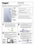
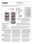
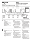
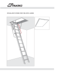
Intuity WiFi to RFLC Bridge
Intuity WiFi RFLC Pont
Intuity WiFi Puente CAFR
Installation Instructions • Notice ďInstallation • Instrucciones de Instalación
Doc. #1507221 04/15 Rev A
Catalog Number(s) • Numéro(s) de Catalogue • Les Numéros de Catalogue:
HA7020
Country of Origin: Made in China • Pays ďorigine: Fabriqué en Chine • Pais de origen: Hecho en China
Power On
Puissance sur
Encendido
WiFi
Solid = Provisioned
Blink = Not Provisioned
Solide = mis en service
Clignote = non provisionnées
Sólido = provisionados
Parpadeo = no asignado
Solid = Paired to HA7000
Blink = Not Paired
Solide = couplé à HA7000
Clignote = non appariés
Sólido = emparejado a HA7000
Parpadeo = no apareados
Reset Button
Bouton de réinitialisation
Botón RESET
INSTALLATION INSTRUCTIONS
Please read these instructions completely before you begin.
NOTICE D’INSTALLATION
Veuillez lire ces instructions dans leur intégralité avant de
commencer.
INSTRUCCIONES DE INSTALACIÓN
Lea estas instrucciones en su totalidad antes de comenzar.
The HA7020 Intuity RFLC Bridge provides a means to connect RFLC and adorne® devices
over WiFi under the control of the Intuity HA7000 Controller.
Le pont de RFLC Intuity HA7020 fournit un moyen de relier RFLC et orner ® appareils via
WiFi sous le contrôle du contrôleur HA7000 Intuity.
El HA7020 Intuity CAFR puente proporciona un medio para conectar CAFR y adorne ®
dispositivos WiFi bajo el control del regulador de HA7000 Intuity.
Connect Button
Bouton connexion
Conectar el botón
AC Adapter
Adaptateur secteur
Adaptador de CA
1
Cut a single-gang sized hole in the wall at a location central to the home WiFi
and/or RFLC devices, and install a single-gang electrical box or mud ring.
Découpez un trou de taille de branchement simple dans le mur à un endroit
central pour les périphériques Wi-Fi et/ou RFLC maison et installer un anneau
de boue ou de la boîte électrique de branchement simple.
2
Orificio de salida simple tamaño en la pared en un lugar central a los
dispositivos WiFi o página Inicio e instalar un anillo simple eléctrico caja o barro.
3
At the RFLC Bridge location, attach the Bridge mounting ring with two screws to the
electrical box or mud ring. Pull the terminated Cat 5 cable from enclosure through
the ring and plug it into the RJ45 jack on the rear of the Bridge. Hang the Bridge on
the four mounting ring hooks.
À l'emplacement du pont de RFLC, fixez le pont montage anneau avec deux vis au
boîtier électrique ou bague de la boue. Tirez les câbles Cat 5 du boîtier par
l'intermédiaire de l'anneau et branchez-le sur la prise RJ45 à l'arrière du pont.
Accrocher le pont sur les quatre crochets de bague de montage.
En la localización del CAFR puente, coloque el puente con dos tornillos a la caja
eléctrica o el anillo de barro el anillo de montaje. El cable Cat 5 terminado del
recinto a través del anillo y conectarlo en el conector RJ45 de la parte posterior del
puente. Pasar el puente en los cuatro ganchos de anillo de montaje.
Screw holes (x2)
Trous de vis (x 2)
Orificios de los
tornillos (x 2)
Mounting ring hooks (x4)
Anneau de fixation
crochets (x 4)
El anillo de montaje
ganchos (x 4)
Run a Cat 5 cable from the enclosure location to the single-gang electrical
box in the wall at desired Bridge mounting location, and terminate both ends
to the TIA/EIA 568A wiring standard with RJ45 plugs.
Exécuter un câble Cat 5 de l'emplacement de l'enceinte à la boîte électrique
branchement simple dans le mur à l'emplacement désiré de montage pont et
extrémités aux normes TIA/EIA 568 a câblage avec fiches RJ45.
Ejecute un cable Cat 5 de la ubicación del recinto a la caja eléctrica simple
en la pared en el lugar de montaje deseado puente y termine ambos
extremos de la norma TIA/EIA-568A cableado con conectores RJ45.
4
At the enclosure, plug the terminated Cat 5 cable from the Bridge into one of
the PW1013 RJ45 output jacks. Plug the PW7760 power supply into an AC
outlet, and its other cable into the 12VDC 1.5A input jack on the PW1013.
The Power out goes to the HA7000.
À l'enceinte, branchez les câbles CAT5 du pont dans une des prises RJ45
PW1013 sortie. Branchez le bloc d'alimentation PW7760 sur une prise
secteur et l'autre câble dans l'alimentation 12Vcc 1,5 a entrée jack sur le
PW1013. L'alimentation de sortie va à la HA7000.
En el recinto, enchufe el cable Cat 5 terminado desde el puente en uno de
los conectores de salida PW1013 RJ45. Conecte la fuente de alimentación
PW7760 en un tomacorriente de CA y su otro cable en el 12VDC 1.5A
entrada jack en el PW1013. La energía va a la HA7000.
RJ45 jack
Prise RJ45
Conector RJ45
Rear of Bridge
Arrière du pont
Parte posterior del
puente
From Bridge
Du pont
Desde puente
To HA7000
À HA7000
A HA7000
From PW7760
De PW7760
De PW7760
5
The physical installation of the RFLC Bridge is
now complete. Your physical installation should
resemble this diagram.
L'installation physique du pont RFLC est
maintenant terminée. Votre installation
physique doit ressembler à ce schéma.
La instalación física del CAFR puente ahora
está completa. Su instalación física debería
parecerse a este diagrama.
6
Configuring an installed RFLC Bridge is a multistep process covered in greater detail in the Intuity Installation Manual (P/N 1308240).
Below are the steps in summary:
a.
b.
c.
d.
When power is applied to the Bridge, it presents itself as a WiFi hotspot.
The Legrand Provioning iOS App must be downloaded to provision the Bridge onto the home’s WiFi network.
The Legrand Intuity iOS App must then be downloaded to add the Bridge to the Intuity system.
Once the Bridge is part of the Intuity system, devices supported by the Bridge may be added to the system.
Configuration d'un pont de RFLC installé est un processus multipas couvert en détail dans le manuel d'Installation Intuity (P/N 1308240).
Voici les étapes en Résumé :
a.
b.
c.
d.
quand la puissance est appliquée au pont, il se présente comme un hotspot WiFi.
l'application iOS de Legrand Provioning doit être téléchargée pour configurer le pont réseau WiFi de la maison.
The Legrand Intuity iOS App doit ensuite être téléchargé pour ajouter le pont au système Intuity.
une fois que le pont fait partie du système Intuity, périphériques pris en charge par le pont peuvent être ajoutés au système.
Configurando un puente CAFR instalado es un proceso de varios pasos cubierto con mayor detalle en el Manual de instalación Intuity
(P/N 1308240). A continuación se muestran los pasos en Resumen:
a.
b.
c.
d.
cuando se aplica energía al puente, se presenta como un hotspot Wi-Fi.
la Legrand Provioning iOS App debe ser descargada a disposición el puente a la red WiFi de la casa.
la Legrand Intuity iOS App entonces debe ser descargado para agregar el puente al sistema Intuity.
una vez que el puente es parte del sistema Intuity, dispositivos soportados por el puente pueden añadirse al sistema.
Doc. #1507221 04/15 Rev A
© Copyright 2015 Legrand All Rights Reserved.
© Copyright 2015 Tous droits réservés Legrand.
© Copyright 2015 Legrand Todos los derechos reservados.
860.233.6251
1.877.BY.LEGRAND
www.legrand.us
www.legrand.ca