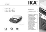
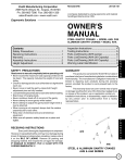
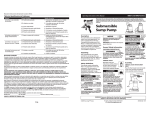
1
Operation and Maintenance Manual
Manuel d’installation et d’entretien
Model No. IX800
Indirect Construction Heater
Radiateur de construction indirecte
800,000 Btu/h
WARNING
Read and follow all installation, and
operating instructions before first use of this
product
AVERTISSEMENT
Lisez et suivez toutes les installation et les
instructions de fonctionnement avant la
première utilisation de ce produit
Retain these instructions for future reference
Veuillez garder ce manuel comme référence ultérieure
Sure Flame Products
A Divison of Haul-All Equipment
4115 - 18 Avenue North
Lethbridge, Alberta T1H 5G1
www.sureflame.com
P/N 974-4135
Rev 1.2 Sep 30, 2014
IX800 Operation & Service Manual
GENERAL HAZARD WARNING
Failure to comply with the precautions and instructions provided with this heater, can result in
death, serious bodily injury and property loss or damage from hazards of fire, explosion, burn,
asphyxiation, carbon monoxide poisoning, and/or electrical shock.
Only persons who can understand and follow the instructions should use or service this heater.
If you need assistance or heater information such as an instruction manual, labels, etc. Contact
the manufacturer.
WARNING
Fire, burn, inhalation, and explosion hazard. Keep solid combustibles, such as building
materials, paper or cardboard, a safe distance away from the heater as recommended by the
instructions. Never use the heater in spaces which do or may contain volatile or airborne
combustibles, or products such as gasoline, solvents, paint thinner, dust particles or unknown
chemicals.
WARNING
Not for home or recreational vehicle use.
MISES EN GARDE GÉNÉRALES
Le non-respect des mises en garde et des instructions fournies avec ce radiateur peut entraîner la mort,
de graves blessures et des pertes matérielles ou des dommages à la propriété résultant d’un incendie,
d’une explosion, de brulures, d’asphyxie, d’empoisonnement au monoxyde de carbone et/ou d’un choc
électrique.
Seules les personnes aptes à comprendre et à suivre les instructions devraient se servir de ce radiateur
ou le réparer.
Si vous avez besoin d’aide ou d’informations concernant ce radiateur, soit une notice d’instructions,
une étiquette, etc., prière de communiquer avec le fabricant.
AVERTISSEMENT
Risque d’incendie, de brûlures, d’inhalation et d’explosion. Garder les combustibles solides, tels les
matériaux de construction, le papier et le carton, à bonne distance de ce radiateur, comme il est recommandé dans les instructions. Ne jamais utiliser cet appareil dans des endroits qui contiennent ou pourraient contenir des combustibles volatiles ou en suspension dans l’air tels l’essence, les solvants, les
diluants pour peinture, les particules de poussières ou des produits chimiques inconnus.
AVERTISSEMENT
Ne pas utiliser dans une maison ou un véhicule de camping.
2
P/N 974-4135 Rev: 1.2
IX800 Operation & Service Manual
Read this Warning First
Lire cet avertissement en premier
This heater is designed and approved for use
as a construction heater under ANSI Z83.72011/CSA 2.14-2011. The primary purpose of
construction heaters is to provide temporary
heating of buildings under construction,
alteration, or repair and to provide temporary
emergency heat. Properly used, the heater
provides safe economical heating. Since
the products of combustion are released, it
is imperative that the flue stack is extended
outside of the enclosed area when the heater is
positioned indoors.
Le radiateur est conçu et approuvé aux fins
d’utilisation comme radiateur de construction en
conformité avec la norme ANSI Z83.7-2011/CSA
2.14-2011. La fonction principale des radiateurs
de construction est de fournir un chauffage
temporaire des bâtiments en construction,
modification ou restauration, et de fournir de la
chaleur en cas d’urgence. Correctement utilisé,
le chauffage fournit de la chaleur de façon sûre
et économique. Étant donné que les produits
de combustion sont rejetés, il est impératif que
le conduit d’évacuation mène à l’extérieur de
l’espace clos lorsque le radiateur se trouve à
l’intérieur.
Ce radiateur n’est pas conçu comme chauffage
au gaz sans ventilation pour pièce d’habitation
selon la norme ANSI-Z21.11.2 et ne doit pas
être utilisé à domicile. La norme ANSI A119.2
(NFPA 501C)-1987 concernant les véhicules
de loisirs interdit l’installation ou l’entreposage
de bouteilles de gaz LP/propane, même
temporairement, à l’intérieur des véhicules de
loisirs. La norme interdit également l’utilisation
de chauffage sans ventilation dans de tels
véhicules.
L’installation doit être conforme aux codes
locaux, ou en l’absence des codes locaux, au
National Fuel Gas Code ANSI Z223.1/NFPA 54
et le Standard
for the Storage and Handling of Liquified
Petroleum Gases ANSI/NFPA 58.
Au canada, toutés les autorties d’inspection
des appareils à gaz exignt que l’installation
des appareils de chauffage et de leurs
accessres soit effectuée par des gaziers
qualifiés.
L’installation doit être conforme au code CSA
B149.1 code d’installation du gaz naturel et
du propane.
Nous ne pouvons pas anticiper chaque
utilisation qui pourrait être faite de nos
radiateurs.
VÉRIFIEZ AUPRÈS DE VOTRE AUTORITÉ
LOCALE EN PRÉVENTION DES INCENDIES
SI VOUS AVEZ DES QUESTIONS SUR LES
RÉGLEMENTATIONS LOCALES.
D’autres normes régissent l’utilisation des
carburants gazeux et des produits générateurs
de chaleur dans des applications spécifiques.
Votre autorité locale peut vous en informer.
This heater is not designed as an Unvented
Gas Fired Room Heater under ANSI-Z21.11.2
and should not be used in the home. ANSI
A119.2(NFPA 501C)-1987 Recreational Vehicle
Standard prohibits the installation or storage of
LP-Gas containers even temporarily inside any
recreational vehicle. The standard also prohibits
the use of Unvented Heaters in such vehicles.
Installation must comply with local codes, or
in the absence of local codes,
with the National Fuel Gas Code ANSI Z223.1/
NFPA 54 and the Standard
for the Storage and Handling of Liquified
Petroleum Gases ANSI/NFPA 58.
Gas inspection authorities in Canada require
that the installation and maintenance of
heaters and accessories be accomplished by
qualified gas fitters.
Installation must comply with local codes,
and with the Natural Gas and Propane
Installation Code CSA-B149.1.
We cannot anticipate every use which may be
made for our heaters.
CHECK WITH YOUR LOCAL FIRE SAFETY
AUTHORITY IF YOU HAVE QUESTIONS
ABOUT LOCAL REGULATIONS.
Other standards govern the use of fuel gases
and heat producing products in specific
applications. Your local authority can advise you
about these
P/N 974-4135 Rev: 1.2
3
IX800 Operation & Service Manual
Table of Contents
Specifications...................................................................................... 5
Installation........................................................................................... 6
Operating Instructions......................................................................... 11
Maintenance....................................................................................... 12
Troubleshooting Chart........................................................................ 16
Wiring Diagrams................................................................................. 28
Parts Diagrams................................................................................... 30
Table des matières
Spécifications...................................................................................... 5
Installation........................................................................................... 6
Mode d’emploi.................................................................................... 11
Entretien............................................................................................. 12
Tableau de dépannage....................................................................... 16
Schémas de câblage.......................................................................... 28
Schémas de pièces............................................................................ 30
4
P/N 974-4135 Rev: 1.2
IX800 Operation & Service Manual
SPECIFICATIONS
Model No. IX800
Capacity / Capacite:800,000 Btu/h (235 kW)
Gas/Gaz:Natural or Propane
Inlet Pressure* / Pression d’arrive*:
max 5 psi (34.5kPa)
min
7” WC (1.74 kPa)
Manifold Pressure / Pression du distributeur
Natural Gas 3.9”WC (0.97 kPa)
Propane
1.9”WC (0.47 kPa)
Orifice Size / Calibre de l’injecteur:
0.581”
Electrical Rating / Puissance Electrique:
208/230 Volts, 27.0/24.4A, 3Ph, 60Hz
208/230 Volts, 43.6/39.4A, 1Ph, 60Hz
Minimum Temperature / température minimale:
-40°C (-40°F)
Duct Diameter / diamètre du conduit:
20” or 2 x 16”
Maximum Duct Length:
100’ (30.5 m)
VentingCategory I
Fuel Consumption / consommation de carburant
Natural Gas 800 ft³/hr
Propane
318 ft³/hr
Certification
CSA 2.14-2011
* Minimum inlet pressure is for purpose of input adjustment
* La pression minimum d’arrivée est en vue de l’ajustement de l’alimentation.
P/N 974-4135 Rev: 1.2
5
IX800 Operation & Service Manual
Installation
Installation
The Sure Flame Model IX800 is an
indirect-fired gas heater intended to be
used primarily for the temporary heating of
buildings under construction, alteration or
repair. Since the products of combustion are
released, it is imperative that the flue stack
is extended outside of the enclosed area
when the heater is positioned indoors. The
flow of supply air and exhaust gasses must
not be obstructed in any manner.
Le modèle Sure Flame IX est un radiateur
au gaz à combustion indirecte prévu pour
être utilisé principalement pour réchauffer
temporairement un bâtiment en cours de
construction, modification ou restauration.
Étant donné que les produits de combustion
sont rejetés, il est impératif que le conduit
d’évacuation mène à l’extérieur de l’espace
clos lorsque le radiateur se trouve à
l’intérieur. L’écoulement d’air d’admission et
des gaz de combustion ne doit en aucune
façon être obstrué.
The equipment shall be installed in
accordance with the National Fuel Code,
ANSI 223.1/NFPA 54, and/or the Natural
Gas and Propane Installation Code CSA
B149.1, and applicable local regulations,
which should be carefully followed in all
cases. Authorities having jurisdiction should
be consulted before installations are made.
The heater shall be used in a horizontal
position on a firm, non-combustible surface.
The electrical grounding of the appliance
shall be in compliance with National
Electrical Code, ANSI/NFPA 70, or the CSA
C22.1, Canadian Electrical Code, Part I
Warning: The installation and maintenance
of the heater must be accomplished by a
qualified service person. The heater should
be inspected before each use and at least
annually.
Warning: Do not use this heater in a
space where gasoline of other liquids with
flammable vapours are stored or used.
L’équipement doit être installé
conformément à la National Fuel
Code, ANSI 223.1/NFPA 54, et/ou la
code d’installation du gaz naturel et du
propane CSA B149.1, et aux règlements
locaux applicables, qui devraient être
respectés dans tous les cas. Les autorités
compétentes devraient être consultées
avant de procéder à l’installation.
Le radiateur devrait être utilisé
horizontalement sur une surface non
combustible ferme.
La mise électrique à la terre de l’appareil se
fera conformément au National Electrical
Code, ANSI/NFPA 70, ou le CSA C22.1,
Code canadien de l’électricité, 1re partie.
Avertissement : Installation et
maintenance du radiateur doivent être
effectuées par un agent de service
qualifié. Le radiateur doit être inspecté
avant chaque utilisation, et au moins une
fois par an.
Avertissement : Ne pas utiliser
le radiateur dans un endroit où on
entrepose ou utilise de l’essence
ou d’autres liquides émanant des
vapeurs inflammables.
6
P/N 974-4135 Rev: 1.2
IX800 Operation & Service Manual
Clearances
Dégagements
Clearance required for combustibles:
Outlet:
10 ft (3 m)
Sides:
2 ft (0.6 m)
Top:
3 ft (0.9 m)
Flue:
18” (45 cm)
Floor:
Noncombustible
Espace dégagé requis pour les combustibles:
Sortie:
10 pi (3m)
Cotes:
2 pi (0.6 m)
Combustion:
18 po (45 cm)
Dessus:
0.9 m
Plancher: Noncombustible
Minimum clearance required to LP Gas
containers:
Outlet:
20 ft (6.1 m)
Top & Sides: 10 ft (3.0 m)
Espace minimum requis pour les contenants de
Gaz PL
Sortie:
20 pi (6.1 m)
Dessus et Cotes: 10 pi (3.0 m)
Position heater properly on a horizontal surface before use.
Placez le radiateur de façon appropriée, sur une
surface horizontale, avant de l’utiliser.
The hose assembly shall be protected from
traffic, building materials and contact with hot
surfaces both during use and while in storage. For use with or without ductwork. Only
ductwork supplied by the manufacturer shall
be used with this heater. For either indoor or
outdoor use. Adequate ventilation must be
provided. This heater is for operation at a
temperature rise from 72°C to 120°C (162°F
to 248°F).
L’ensemble de flexibles devra être protégé de
la circulation, des matériaux de construction et
du contact avec des surfaces chaudes durant
l’utilisation et durant l’entreposage. Pour utilisation avec ou sans réseau de gaines. Seulement
réseau de gaines fourni par le fabricant sera utilisé avec cet radiateur. Pour utilisation à l’intérieur
ou à l’extérieur. La ventilation doit être adéquate.
Cet aérotherme fonctionne a une élévation de
température de 72°C a 140°C (162°F a 248°F)
All gas inspection authorities in Canada
require that the installation and maintenance
of heaters and accessories shall be accomplished by qualified gas fitters.
Au canada, toutés les autorties d’inspection des
appareils à gaz exignt que l’installation des appareils de chauffage et de leurs accessres soit
effectuée par des gaziers qualifiés.
Installation must comply with the Natural Gas
and Propane Installation Code, CSA B149.1.
L’installation doit être conforme au code CSA
B149.1 code d’installation du gaz naturel et du
propane.
Ducting
The IX800 can be ducted on both the inlet
and outlet. The inlet duct can be up to 50’
of smooth 16” metal duct The outlet duct
shall be of a material able to withstand temperatures of up to 300°F. Total outlet duct
length may be up to 300’ of straight, smooth,
20” metal duct. Use of flexible ducts, smaller
ducts, or bends in the ducts will reduce the
allowable length and may result in excessive
cycling of the burner.
P/N 974-4135 Rev: 1.2
Conduits
Le radiateur IX800 peut être canalisé à l’orifice
d’entrée et de sortie. La canalisation d’entrée
peut atteindre jusqu’à 50 pieds de conduits en
métal lisse de 16 po. La canalisation de sortie
sera fabriquée d’un matériau pouvant résister
à des températures allant jusqu’à 300 °F. La
longueur totale de la canalisation de sortie peut
atteindre jusqu’à 300 pieds de conduits en métal
lisse droits de 20 po. L’utilisation de conduites
flexibles, de plus petites conduites ou de coudes
dans la canalisation réduira la longueur permise
et peut entraîner des fluctuations excessives du
brûleur.
7
IX800 Operation & Service Manual
Venting
This equipment requires CLASS A venting
to the exterior. The vent connector should
be designed for a negative pressure and be
constructed of materials having corrosion
resistance and durability to heat at least
equivalent to that of No. 24 GSG galvanized
steel.
Venting must comply with the Natural Gas
and Propane Installation Code CSA B149.1,
as well as other local regulations that may
apply.
Flue Diameter10”8”
Min. vertical height
4’
4’
Max. lateral length*
15’
0’
Max. # of added elbows** 2
0
*Lateral lengths must have a minimum 10%
rise.
** A minimum vertical length of 2’ is required
before the first elbow and after the last
elbow.
Consult the manufacturer for additional
venting options.
Rated flue gas temperature 446°F (230°C)
Rated vent pressure - Negative
Category I
Gas Connections Ensure the correct regulator is used to
supply the heater with maximum inlet
pressure of 5 psi. Excessive pressure will
damage components and void the warranty.
Visually inspect the fuel supply hose
assembly. Ensure that it is protected from
traffic, building materials, and contact with
hot surfaces. Replace if there is evidence of
excessive wear or abrasion.
After installation, check for gas leaks by
applying a soapy solution at each piping and
hose assembly connection.
8
Ventilation
Cet équipement exige une ventilation vers
l’extérieur de type A. Le raccord d’évent
devrait être conçu pour une pression négative
et construit de matériaux ayant une résistance
à la corrosion et une durabilité à la chaleur
équivalant au moins à l’acier galvanisé no 24
GSG.
La ventilation doit se conformer à la Norme
concernant les Installations au gaz naturel et
au propane CSA B149.1, ainsi qu’aux autres
règlements locaux qui peuvent s’appliquer.
Conduit d’évacuation 10 po 8 po
Hauteur min. verticale
4 pi
4 pi
Longueur max. latérale* 15 pi
0 pi
Nombre max. de coudes**2
0
*Les longueurs latérales doivent avoir une
inclinaison d’au moins 10 %.
**Une longueur verticale d’au moins 2 pieds
est requise avant le premier coude et après le
dernier coude.
Consulter le fabricant pour des options de
ventilation supplémentaires.
Temperature nominale du gaz de combustion
446°F (230°C)
Pression nominale de l’event - Négative
Catégorie I
Raccords au gaz S’assurer que le régulateur approprié est
utilisé pour fournir la pression d’admission
maximale de 5 psi au radiateur. Une pression
excessive endommagera les pièces et
annulera la garantie.
Inspecter visuellement l’ensemble du tuyau
d’alimentation. S’assurer qu’il est protégé de
la circulation, des matériaux de construction
et du contact avec des surfaces chaudes.
Le remplacer, s’il y a des signes d’usure ou
d’abrasion excessive.
Après l’installation, vérifier s’il ya des fuites de
gaz en appliquant une solution savonneuse à
chaque raccord de la canalisation.
P/N 974-4135 Rev: 1.2
IX800 Operation & Service Manual
INSTALLATION USING A PROPANE SUPPLY TANK
1 When installing the heater for use with propane gas, set the gas selector valve to “Propane”
and lock in position.
2 Arrange the propane supply system to provide for vapour withdrawal from the operating
container. Supplying liquid propane to the heater is dangerous and will damage the
components. Another regulator must be installed on the heater to reduce the pressure
from this regulator to a maximum inlet pressure of 5 psi.
3 Ensure that for the surrounding temperature the size and capacity of the propane supply
container is adequate to provide the rated Btu/h input to the heater.
4 Turn off the propane supply valve at the container when the heater is not in use.
5 The installation must conform with local codes, or in the absence of local codes, with the
Standard for the Storage and Handling of Liquedied Petroleum Gases, ANSI/NFPA 58 or
the Natural Gas and Propane Installation Code CSA-B149.1.
6 When the heater is to be stored indoors the propane container must be disconnected from
the heater and the container moved away and stored in accordance with the above national
standards.
INSTALLATION FOR NATURAL GAS APPLICATIONS
1 When installing the heater for use with natural gas, set the gas selector valve to the “Natural”
position.
2 A regulator must be installed on the heater to ensure that the pressure to the heater does
not exceed 1/2 psi inlet pressure.
3 The installation of this heater to a natural gas supply must conform with all applicable local
codes, or in the absence of local codes, with the National Fuel Gas Code ANSI Z223.1/
NFPA 54 or the Natural Gas and Propane Installation Code CSA-B149.1.
P/N 974-4135 Rev: 1.2
9
IX800 Operation & Service Manual
IX410 Operation & Service Manual
LPG - PROPANE FUEL VAPORIZATION RATE
The following chart shows the amount of BTU's that various sizes of tanks will produce on the average at specific
temperatures and regular atmospheric conditions.
Tank Size
Gallons
(Pounds)
150
(600)
250
(1000)
500
(2000)
1000
(4000)
Maximum intermittent withdrawal rate (BTU/hr) without tank frosting*
if lowest outdoor temperature (average for 24 hours) reaches.
+40 F. +30 F. +20 F. +10 F.
0 F.
-10 F
-20 F. -30 F.
214,900 187,900 161,800 148,000 134,700 132,400 108,800 107,100
288,100 251,800 216,800 198,400 180,600 177,400 145,800 143,500
478,800 418,600 360,400 329,700 300,100 294,800 242,300 238,600
852,800 745,600 641,900 587,200 534,500 525,400 431,600 425,000
* Frosting on the outside of the tank acts as an insulator, reducing the vaporization rate.
MAXIMUM BTU CONTENT (PROPANE)
The following table shows the maximum BTU's that a cylinder contains.
CYLINDER SIZE
BTU CONTENT
100 pound
2,159,100
250 gallon USA
22,922,500
500 gallon USA
45,845,000
1000 gallon USA
91,690,000
CAUTION: In extremely cold weather it is impossible to completely empty a propane cylinder.
PRESSURE & FLOW EQUIVALENTS
1 Std. Atmosphere =
1" Water Column (W.C.) =
11" Water Column =
1 lb./sq. in. (psig) =
1" Mercury =
1 Std. Cubic Ft./Hr. =
1 BTU/Hr. =
10
14.73 lb./sq. in. =
0.58 oz./sq. in. =
0.4 lb./sq. in.=
27.71" W.C. =
0.49 psig =
2,500 BTU/Hr. =
0.2931 Watts
1.014 bar
2.49 millibar
27.39 millibar
0.0689 bar
33.86 millibar
0.02832 cu. m/hr.
P/N 974-4135 Rev: 1.2
IX800 Operation & Service Manual
Operating Instructions
1) Set GAS SELECTOR VALVE to gas being used.
NOTE: The Selector Valve must be locked in position.
2) Ensure firing valve (manual valve nearest the burner) is in the “ON” position.
3) Connect Power: Use appropriate power supply as indicated by the ELECTRICAL
RATING information.
4) Open gas supply.
5) Press and release START switch. START light will come on. Set thermostat to desired
setting. Burner Blower will start after about 5-30 seconds. Flame will ignite after another
20 seconds.
6) Heater will switch between high flame and no flame as required to maintain the desired
temperature.
7) To stop, press STOP switch and turn gas off. Burner blower will stop after about 20
seconds. Main blower will continue to cycle until heat exchanger has cooled.
Mode d’emploi
1) Régler la VALVE DE GAS SELECTION selon le type de gaz utilisé.
Á NOTER: La valve de sélection doit étre immobilisée a l’aide du dispositif de
verrouillage fourni a cet effet.
2) S’assurer que la valve d’allumage (valve manuelle la plus proche du brûleur) est dans la
position “ON”.
3) Brancher le circuit électrique - se servir dùne source làlimentation équivalente à la
PUISSANCE ELECTRIQUE indiquée ci-haut.
4) Ouvrir l’alimentation de gaz.
5) Enfoncer et relâcher le sélecteur START. Le témoin START sàllumera. Régler le
thermostat à la température désirée. La flamme s`àllumera 20 secondes plus tard.
6) Le radiateur commutera entre flamme haute et flamme absente, selon les besoins, pour
maintenir la température sélectionnée.
7) Pour éteindre, enfoncer STOP et couper le gaz. La soufflante s`àrrêtera enfoncer stop
et couper le gaz. La soufflante s`arrêtera envirn 20 secondes plus tard. La soufflante
principale continuera de cycler jusqu`àl`échangeur de chaleur se retroidit.
P/N 974-4135 Rev: 1.2
11
IX800 Operation & Service Manual
Maintenance
Warning: Disconnect gas and electrical supplies before servicing.
Weekly:
Gas Hose
Air flow
Bearings
Check for cracks and damaged connectors
Remove any obstructions to air flow
Lubricate bearings according to details below
Monthly:
Cords and Connectors Check for cracks, exposed wires, and dirt in electrical connectors
Physical Integrity
Check for damage to body, louvers, and inlet screens that may obstruct
air flow and impact combustion quality
Belts
Replace belt if cracked or worn according to details below.
Ensure belt tensioner is in place and tensioner roller is running smoothly.
End of Season:
Combustion Chamber
Remove burner assembly
Clean inside of combustion chamber with a wire brush. Vacuum all ash
and soot from combustion chamber.
Inspect combustion chamber for any damage. Do not use a heater that
has a hole in the combustion chamber.
Burner
Remove burner from burner assembly
Clean flame rod and igniter with solvent or emery cloth. Inspect for
cracked ceramic. Ensure they are properly centered in the burner
openings. Inspect wires for cracks or evidence of overheating
Ensure burner head screws are tight.
Ensure openings in orifice plate (located inside the burner pipe) are not
blocked. Ensure gasket and door seal are in place and not damaged.
Electrical components Check all wiring for loose, cracked, or overheated wires and connectors.
Replace if necessary.
Ensure ground wires are properly connected.
Ensure control box seal is in place and not damaged.
Wipe dirt from motors. Motors have sealed bearings and do not require
lubrication.
Valve Train
Verify that manifold pressure matches the specification label. Adjust
regulator pressure if necessary.
Inspect strainer and clean if necessary.
Using soapy water or gas leak detector, check all gas connections for
leaks.
Impellers
Remove any dirt build-up on both burner and blower impellers.
Inspect impellers for loose or damaged fins.
Run heater and check for vibration.
Replace impellers that are damaged or causing vibration.
Body
Ensure all panels and shields are in place and that fasteners are tight.
12
P/N 974-4135 Rev: 1.2
IX800 Operation & Service Manual
Entretien
Avertissement : Débrancher les alimentations en gaz et en électricité avant d’effectuer l’entretien.
Toutes les semaines :
Tuyaux de gaz
Vérifier s’il y a des fissures et des raccords endommagés
Débit d’air
Retirer les obstructions à la circulation de l’air
Tous les mois :
Cordons et
connecteurs
Vérifier s’il y a des fissures, des câbles à découvert et de la saleté dans les
connecteurs électriques
Intégrité physique
Vérifier s’il y a des dommages au corps, aux louvres et grilles d’entrée qui peuvent
entraver la circulation de l’air et avoir une incidence sur la qualité de la combustion
Courroie
Remplacer la courroie si elle est fendue ou usée.
S’assurer que le tendeur de courroie est en place et que le rouleau tendeur
fonctionne en douceur.
Fin de la saison :
Chambre de
combustion
Retirer l’ensemble de brûleur.
Nettoyer l’intérieur de la chambre de combustion à l’aide d’une brosse métallique.
Enlever toute les cendres et la suie de la chambre de combustion à l’aide d’un
aspirateur.
Vérifier s’il y a des dommages à la chambre de combustion. Ne pas utiliser un
radiateur ayant un trou dans la chambre de combustion.
Brûleur
Retirer le brûleur de l’ensemble de brûleur.
Nettoyer l’électrode de détection de flamme et l’allumeur avec un solvant ou une toile
d’émeri. Vérifier s’il y a des fissures dans la céramique. S’assurer qu’ils sont bien
centrés dans l’ouverture du brûleur.
Vérifier s’il y a des fissures ou des signes d’excès de chaleur dans les câbles.
S’assurer que les vis de la tête de brûleur sont serrées.
S’assurer que les ouvertures de la plaque à orifice (située à l’intérieur du tuyau du
brûleur) ne sont pas bloquées.
S’assurer que le joint d’étanchéité et le joint d’étanchéité de la porte sont en place et
ne sont pas endommagés.
Éléments
électriques
Vérifier s’il y a des câbles et des connecteurs desserrés, fissurés ou ayant des signes
d’excès de chaleur. Les remplacer, au besoin.
S’assurer que les fils de mise à la terre sont bien raccordés.
S’assurer que le joint d’étanchéité de la boîte des commandes est en place et n’est
pas endommagé.
Essuyer la saleté des moteurs. Les moteurs ont des coussinets scellés. Ils n’exigent
pas de lubrification.
Organes de
distribution
Vérifier que la pression de la rampe à gaz correspond à celle inscrite sur l’étiquette de
spécifications. Régler la pression du régulateur, au besoin.
Inspecter la crépine et la nettoyer, au besoin.
À l’aide d’eau savonneuse ou d’un détecteur de fuite de gaz, vérifier s’il y a des fuites
au niveau des raccords au gaz.
Rouets centrifuges
Enlever l’accumulation de saleté sur le brûleur et les rouets centrifuges du ventilateur.
Vérifier si les pales des rouets centrifuges sont desserrées ou endommagées.
Faire fonctionner le radiateur et vérifier s’il y a des vibrations.
Remplacer les rouets centrifuges qui sont endommagés ou qui causent des
vibrations.
Corps
S’assurer que tous les panneaux et tous les écrans sont en place et que les attaches
sont bien serrées.
P/N 974-4135 Rev: 1.2
13
IX800 Operation & Service Manual
Lubricating Bearings:
Warning: Disconnect power before servicing bearings.
The main blower has two bearings. They need to be periodically lubricated according to the
schedule below. Some situations may require a change in lubricating periods as dictated
by experience. Generally, a lower quantity of grease at frequent intervals is more effective
than a greater quantity at extended lubrication intervals. Select a grease that is compatible
with a lithium or lithium complex grease.
Recommended Lubrication Schedule
Lubrication Interval in Weeks
Hours Run Per Day
Main Blower
(2.7 gram per bearing)
8
16
24
5
2
1
Storage: If equipment will be idle for some time, before shutting down, add compatible
grease to the bearing until grease purges from the seals. This will ensure protection of
the bearing, particularly when exposed to severe environmental conditions. After storage
period, add fresh grease to the bearings before starting.
Replacing Belts:
Warning: Disconnect power before servicing belts.
The main blower uses a double belt transmission. It requires the belts to be paired, and
both need to be changed at the same time. Ensure that the blower belt tensioner is in place
and set at 25°-30°, and that the tensioner roller is running smoothly. Replace if worn.
Adjusting Manifold Pressure:
Connect manometer to the port on the inlet flange of the regulator. While heater is
operating, verify that the inlet pressure is between 7” WC and 5 psi. Connect manometer to
manifold pressure tap on burner gas supply line. Ensure that the gas selector valve is set to
the proper fuel. While the heater is operating check the manifold pressure. If the manifold
pressure differs from specifications, re-adjust.
The adjusting screw is located on side of regulator valve. Use 2.5mm Allen wrench.
Remove the manometer and securely tighten the manifold pressure tap.
14
P/N 974-4135 Rev: 1.2
IX800 Operation & Service Manual
SETTING FAN LIMIT SWITCHES
The fan limit switch is factory set and should
not normally need to be adjusted. If it is out
of adjustment, follow these procedures:
To set pointers, hold dial securely with one
hand and move the pointers with the other
hand using “limit stop tool”. Do not force
the pointers past any stops on the dial even
though the dial may be graduated beyond
the stops.
Top Limit
Move the right hand pointer so that its high
side of lever indicates 200°F.
Top Fan
Move the “Fan On” pointer so that its high
side of lever indicates 100°F. This is the
temperature at which the blower will start.
Move the “Fan Off” pointer so that its high
side of lever indicates 90°F. This is the
temperature at which the blower will stop.
Side Limit
Move the right hand pointer so that its high
side of lever indicates 250°F.
Side Fan
Move the “Fan On” pointer so that its high
side of lever indicates 100°F. This is the
temperature at which the blower will start.
Move the “Fan Off” pointer so that its high
side of lever indicates 90°F. This is the
temperature at which the blower will stop.
RÉGLAGE DU CADRAN
Le commutateur de limite du ventilateur est
réglée en usine et ne devrait normalement
pas besoin d’être ajustés. Si elle est hors
d’ajustement, suivez ces procédures:
Pour régler les repères, maintenir le cadran
fermement en place avec une main et
déplacer les repères avec “limiteur butée
outil”. Ne pas forcer les repères au-delà
des butées du cadran, même s’il y a des
graduations sur le cadran au-delà des
butées.
Limite
Déplacer le repère droit pour que son
bord droit indique 200°F pour le haut
commutateur de limite et 250°F pour le
commutateur de limite côté.
Ventilateur
Déplacer le repère central de marche du
ventilateur (Fan On) pour que son bord droit
indique 100°F. Déplacer le repère gauche
d’arrêt du ventilateur (Fan Off) pour que son
bord droit indique 90°F. C’est le température
qui le ventilateur sera arrêté.
POUR DÉGAGER LA BUTÉE,
INSÉRER UN FIL RIGIDE
DANS LE TROU
LIMITEUR BUTÉE
OUTIL
PLAQUE GRADUÉE
BUTÉE RÉGLABLE
DU LIMITEUR
INDICATEURD’ARRÉT
DU VENTILATEUR
INDICATEUR DE MARCHE
DU VENTILATEUR
THIS IS A “SAFETY STOP”. DO NOT ALTER
HIGH SIDE OF LEVERS INDICATE TEMPERATURE SETTINGS
P/N 974-4135 Rev: 1.2
INDICATEUR DU LIMITEUR
(RÉGLÉ EN USINE A 200°F)
IL SAGIT D’UNE BUTÉE DE SÉCURITÉ, NE PAS DÉPLACER
LA LECTURE S’EFFECTURE À LA CÔTÉ HAUT DE L’INDICATEUR
15
IX800 Operation & Service Manual
Troubleshooting
The troubleshooting section has been divided in to five tables. Choose the
appropriate table from the list below:
Chart A – Burner blower does not start, No spark, No Flame,
Chart B – Burner blower starts, No spark, No flame,
Chart C – Burner blower starts, Spark, No flame,
Chart D – Burner blower starts, Spark, Flame goes out after four seconds
Chart F – Other problems during operations
16
P/N 974-4135 Rev: 1.2
IX800 Operation & Service Manual
Heater Troubleshooting
Symptom
Possible Problems
Ignition controller error light on steady.
Ignition controller failure.
Error
Light
Burner blower does not start, no spark, no flame
Steady
Green light is on. Single flash of the error light Air switch failure.
on ignition controller after 30 seconds.
Burner motor failure.
1
Burner won’t start when call for heat or jumper Low voltage fuse (T5A) burned out
plug in. No green light but main blower turns
Fuse (3A) burned out.
on if fan manual button is pushed in. Power at
Power transformer burned out.
the VFD.
-
Control box electric heater always on. Control
box cooling fan always on.
Preheat thermostat failure.
-
Preheat relay (1) failure.
-
Green light always on. Heater stuck on
standby.
Preheat relay (2) failure.
-
Green light on. Orange light on. Control box
cooling fan doesn’t work. Heater stuck on
standby.
Preheat relay (1) failure.
-
Green light on. Orange light on. Control box
cooling fan on. Heater stuck in standby.
Preheat relay (1) failure.
-
Preheat relay (2) failure.
-
Electric preheating element failure.
-
Green light is on when the start button is
pressed, but turns off when the button is
released.
Logic relay failure.
-
Stop switch failure.
-
Green light is on. No error light on ignition
controller.
Thermostat failure.
-
No green light when start button is pressed.
No power at the VFD.
L2/L3 3 phase or L/N 1 phase contact
on power selector switch failure.
-
No electrical supply.
-
L1/L2 3 phase or L/N 1 phase missing.
-
L2/L3 3 phase or L/N 1 phase fuse
blown.
-
No green light when the start button is
pressed. Green light comes on when the
manual button on the logic relay is pressed.
Start switch failure.
-
T5A fuse repeatedly burning out.
Overload (or short) in 24VAC circuit
(secondary transformer voltage).
-
Heater operates on 1 phase or 3 phase only.
Power switch locked in one position.
-
P/N 974-4135 Rev: 1.2
1
-
17
IX800 Operation & Service Manual
Burner blower starts, no spark, no flame
Possible Problems
Single error light flash on ignition
controller after 30 seconds.
Air switch failure.
1
Air switch set to too high a pressure.
1
Air tubes plugged or installed in
wrong air switch position.
1
Burner motor won’t turn on if any draft
is present. One error flash on ignition
controller.
Air switch set to too low a pressure.
1
Burner motor runs from power up. When
start button is pushed green light is on
and one error flash on ignition controller.
Ignition controller failure. (Ignition
controller F1 terminal powered.)
1
Burner motor relay failure.
1
No spark after 30 seconds prepurge (no
visible arcing). Three error flashes on
ignition controller. Burner motor shuts
down after 45 seconds of postpurge.
Ignition transformer failure.
3
Igniter shorting to ground.
3
Cracked spark plug ceramic insulator.
3
Error
Light
Symptom
Burner blower starts, spark, no flame
Possible Problems
Burner motor starts but no flame after 30
seconds prepurge. Three error flashes
on ignition controller.
Output limit switch failure.
3
Top fan/limit switch failure.
3
Tilt switch failure.
3
Flame rod and spark plug wires
reversed.
3
Manual valve closed.
3
Solenoid valve failure.
3
Upstream regulators installed
backwards.
3
Inlet pressure too high.
3
Error
Light
Symptom
Burner won’t ignite or occasionally
Strainer plugged or dirty.
ignites with poor combustion. Three error Manifold pressure set too low.
flashes on ignition controller.
Burner orifices plugged or dirty.
Burner air inlet obstructed.
18
3
3
3
1
P/N 974-4135 Rev: 1.2
IX800 Operation & Service Manual
Burner blower starts, spark, flame goes out after four seconds
Possible Problems
Three error flashes on ignition controller.
Flame turns off after 4 sec TFI.
Bent flame rod.
3
Wet flame rod.
3
Cracked flame rod ceramic insulator.
3
Burner not grounded.
3
Ignition controller failure.
3
Symptom
Possible Problems
Error code on the VFD. Contact
manufacturer.
Burner starts but main blower motor can’t
accelerate to full RPM (hamming noise
& excessive amperage draw). VFD trips
during blower motor acceleration. Heater
starts but shuts off when main blower
motor starts.
VFD failure.
Error
Light
Malfunctioning main blower
Error
Light
Symptom
Low voltage (long extension cord,
low cord gauge or too many items on
circuit).
Poor quality power (such as from a
generator).
Improper voltage.
Incorrect VFD frequency setting.
Main blower motor failure.
-
Broken belt.
Motor connected in reverse.
Main blower motor can’t accelerate to full Belt too tight.
RPM. VFD trips off during blower motor
acceleration. Vibration in main blower.
Bearings seized.
Contact manufacturer.
Main blower motor never starts. Three
Preheat relay (2) failure.
error flashes on ignition controller.
Excessive noise or vibration.
Damaged or unbalanced main blower
impeller.
When cooling, main blower works in
Side fan/limit switch failure.
short burst cycles.
Squeak noise during main blower motor Loose belt.
start up. Noisy main blower operation.
Vibrations in main blower.
-
Incorrect motor RPM.
Main blower motor won’t turn (VFD
works) or noisy. VFD trips. Main blower
motor won’t turn if manual pushbutton is
pushed in.
Motor starts, but little or no air flow.
P/N 974-4135 Rev: 1.2
-
3
-
19
IX800 Operation & Service Manual
Other problems during operation
Possible Problems
Main blower fan takes a long time to start.
Possible exchanger damage.
Burner turns off shortly after it’s turned on.
Burner turns off frequently.
Control box cooling fan is always running.
Average temperature in control box low.
Control box cooling fan never starts. If in a
warm environment, VFD may overheat and
fail.
Top fan/limit switch failure.
-
Side fan/limit switch failure.
-
Control box cooling fan limit switch
failure.
Control box cooling fan limit switch
failure.
Control box cooling fan burned
out.
Heater connected to liquid
propane supply.
Manifold pressure set too high.
Changeover valve set to natural
gas when connected to propane.
L1 3 phase missing.
L1 fuse blown.
L1 contact on power selector
switch failure.
Preheat relay (2) failure.
-
Start switch failure.
Stop switch failure.
Preheat limit switch failure.
-
Green light burned out.
-
Preheat limit switch failure.
Gas hose too small, too long, or
blocked.
3
Preheat relay (2) failure.
Thermostat failure.
-
Excessive yellow flame. Burner rumbling.
Main blower fan starts then shortly after,
supply panel breaker trips.
Green light on. Orange light and heater turn
on and off sporadically.
Heater does not stop when the stop button is
pressed.
Heater operates normally. Average
temperature in control box lower. VFD
susceptible to fail while operating at a low
temperature.
Heater operates normally. Green power light
off.
Heater operates normally. No preheating.
Heater shuts off or heater ignites but shuts off
after awhile. Three error flashes on ignition
controller.
Heater starts immediately in cold weather.
Heater does not turn off when the thermostat
is turned to minimum. No error light on ignition
controller.
20
Error
Light
Symptom
-
P/N 974-4135 Rev: 1.2
IX800 Operation & Service Manual
Inlet pressure drops under 7”. Valve train
pressure below nominal value. Heater ignites
but shuts off after awhile. Three error flashes
on ignition controller.
Burner cycles on and off frequently.
Low power output. Excessive CO from
exhaust.
Noise and/or vibration in burner blower. Poor
combustion. Burner turns off. One error flash
on ignition controller.
Orange light always off.
Propane tank too small to vaporize
fast enough or tank freezes.
Low inlet pressure.
3
Ducts too long, too small, or
obstructed.
Changeover valve set to propane
when connected to natural gas.
Damaged or unbalanced burner
blower impeller.
-
Preheat relay (1) failure.
Orange light burned out.
Orange light always on.
Preheat relay (1) failure.
Heater runs very hot.
Both output limit switch and side
fan/limit switch fail to operate.
Heater does not turn off when thermostat
Solenoid valve leaks.
turned to minimum. Two error flashes on the
Solenoid valve installed
ignition controller.
backwards.
Solenoid valve stuck open.
Heater starts normally. Doesn’t cycle with long Side fan/limit switch failure.
ducts. Shuts down with three error flashes on
the ignition controller module.
P/N 974-4135 Rev: 1.2
3
1
Y
2
2
2
3
21
IX800 Operation & Service Manual
Tableau de dépannage
Le ventilateur du brûleur ne s’allume pas, aucune étincelle, aucune flamme
Problème possibles
Témoin d’erreur solide sur la commande
d’allumage.
Témoin vert allumé. Clignotement simple du
témoin d’erreur sur la commande d’allumage
après 30 secondes.
Défaillance de la commande
Solide
d’allumage
Défaillance du commutateur de
1
débit d’air.
Défaillance du moteur du brûleur.
1
Le fusible à faible tension (T5A) a
sauté.
Le fusible (3A) a sauté.
Le transformateur d’alimentation
a sauté.
Le brûleur ne démarre pas lorsque le
thermostat ou la prise volante sont branchés.
Le témoin vert est éteint, mais le ventilateur
principal se met en marche si on appuie sur
le bouton manuel du ventilateur. Courant
électrique au niveau du variateur de
puissance.
Le radiateur électrique de la boîte des
commandes est toujours en marche. Le
ventilateur de la boîte des commandes est
toujours en marche.
Témoin
d’erreur
Symptôme
Défaillance du thermostat de
préchauffage.
Défaillance du relais (1) de
préchauffage.
Défaillance du relais (2) de
préchauffage.
Défaillance du relais (1) de
préchauffage.
-
Défaillance du relais (1) de
préchauffage.
Défaillance du relais (2) de
préchauffage.
Défaillance de l’élément de
préchauffage électrique.
Le témoin vert s’allume lorsqu’on appuie sur
Défaillance du relais logique.
le bouton de mise en marche, mais s’éteint
Défaillance de l’interrupteur
lorsqu’on le relâche.
d’arrêt.
Témoin vert allumé. Aucun témoin d’erreur sur Défaillance du thermostat.
la commande d’allumage.
-
Le témoin vert est toujours allumé. Le
radiateur est coincé à la position veille.
Le témoin vert est allumé. Le témoin orange
est allumé. Le ventilateur de la boîte des
commandes ne fonctionne pas. Le radiateur
est coincé à la position veille.
Le témoin vert est allumé. Le témoin orange
est allumé. Le ventilateur de la boîte des
commandes fonctionne. Le radiateur est
coincé à la position veille.
22
-
-
P/N 974-4135 Rev: 1.2
IX800 Operation & Service Manual
Le témoin vert reste éteint lorsqu’on appuie
sur le bouton démarrer. Il y a du courant
électrique au niveau du variateur de
puissance.
Aucun témoin vert lorsqu’on appuie sur le
bouton de mise en marche. Le témoin vert
s’allume lorsqu’on appuie sur le bouton de
relais logique.
Le fusible T5A s’éteint à maintes reprises.
Le radiateur fonctionne sur 1 phase ou
3 phases uniquement.
Contact à la phase L2/L3 3
ou la phase L/N 1 pendant la
défaillance du commutateur
d’alimentation.
Aucune alimentation électrique.
Absence de la phase L1/L2 3 ou
la phase L/N 1.
Le fusible de la phase L2/L3 3 ou
de la phase L/N 1 a sauté.
Défaillance de l’interrupteur de
démarrage.
-
Surcharge (ou pénurie) dans
le circuit 24VAC (tension d’un
transformateur secondaire).
L’interrupteur d’alimentation est
verrouillé dans une position.
-
-
-
Le ventilateur du brûleur s’allume, aucune étincelle, aucune flamme
Problème possibles
Clignotement simple du témoin d’erreur sur la
commande d’allumage après 30 secondes.
Défaillance du commutateur de
débit d’air.
Le commutateur de débit d’air est
réglé à une trop haute pression.
Les conduits d’air sont bouchés
ou insérés à la mauvaise position
du commutateur de débit d’air.
Le commutateur de débit d’air est
réglé à une trop faible pression.
1
Défaillance de la commande
d’allumage. (La commande
d’allumage F1 est alimentée par
la borne.)
Défaillance du relais du moteur
du brûleur.
Défaillance de la commande
d’allumage.
Court-circuit de l’allumeur au sol.
L’isolateur en céramique de la
bougie d’allumage est craqué.
1
Le moteur du brûleur ne s’allume pas s’il y
a un courant d’air. Clignotement simple du
témoin d’erreur sur la commande d’allumage.
Le moteur du brûleur fonctionne dès le
démarrage. Lorsqu’on appuie sur le bouton
de démarrage, le témoin vert s’allume et le
témoin d’erreur sur la commande d’allumage
clignote une fois.
Il n’y a pas d’étincelle après la prépurge
de 30 secondes (aucune production
d’étincelle visible). Le témoin d’erreur de la
commande d’allumage clignote trois fois.
Le brûleur s’arrête après une post-purge de
45 secondes.
P/N 974-4135 Rev: 1.2
Témoin
d’erreur
Symptôme
1
1
1
1
3
3
3
23
IX800 Operation & Service Manual
Le ventilateur du brûleur s’allume, étincelle, aucune flamme
Problème possibles
Témoin
d’erreur
Symptôme
Le moteur du brûleur démarre, mais il
n’y a pas de flamme après la prépurge
de 30 secondes. Le témoin d’erreur
de la commande d’allumage clignote
trois fois.
Défaillance de l’interrupteur de fin de
course de la sortie.
Défaillance de l’interrupteur de fin de
course/du ventilateur principal.
Défaillance de l’interrupteur à bascule.
Fils de l’électrode de detection de flamme
et de la bougie d’allumage inversés.
Valve manuel fermée.
Défaillance de la vanne
électromagnétique.
Les régulateurs en amont ont été installés
à l’envers.
La pression d’admission est trop élevée.
Le brûleur ne s’allume pas ou s’allume Crépine bouchée ou sale.
parfois avec une mauvaise combustion. Pression de la rampe à gaz trop faible.
Le témoin d’erreur de la commande
Orifices du brûleur bouchés ou sales.
d’allumage clignote trois fois.
Admission d’air du brûleur obstrué.
3
3
3
3
3
3
3
3
3
3
3
1
Le brûleur s’allume, mais la flamme s’éteint après environ quatre secondes
Problème possibles
Le témoin d’erreur de la commande
d’allumage clignote trois fois.
L’électrode de détection de flamme est
pliée.
Électrode de détection de flamme
mouillée.
L’isolateur en céramique de l’électrode
de détection de flamme est craqué.
Le brûleur n’est pas mis à la terre.
Défaillance de la commande d’allumage.
24
Témoin
d’erreur
Symptôme
3
3
3
3
3
P/N 974-4135 Rev: 1.2
IX800 Operation & Service Manual
Symptôme
Problème possibles
Code d’erreur sur le variateur de fréquence.
Communiquer avec le fabricant.
Le brûleur se met en marche, mais le moteur
du ventilateur principal ne peut pas accélérer à
plein régime (bruit et courant tiré excessif). Le
variateur de fréquence se déclenche pendant
l’accélération du moteur du ventilateur. Le
radiateur se met en marche, mais s’arrête
lorsque le moteur du ventilateur principal se
met en marche.
Défaillance du variateur de
fréquence.
Faible tension (longue rallonge
électrique, jauge du câble trop
petit or trop d’articles sur le
circuit).
Puissance de faible qualité
(comme celle provenant d’une
génératrice).
Mauvaise tension.
Paramètres incorrects du
variateur de fréquence.
Défaillance du moteur à soufflerie
principal.
Tr/min du moteur incorrects.
Le moteur du ventilateur principal ne se met
pas en marche (le variateur de fréquence
fonctionne) ou est bruyant. Le variateur
de fréquence se déclenche. Le moteur du
ventilateur principal ne se met pas en marche
si on appuie sur le bouton manuel.
Le moteur à soufflerie démarre, avec peu or
pas de circulation d’air.
Le moteur du ventilateur principal ne peut
pas accélérer à plein régime. Le variateur de
fréquence se déclenche pendant l’accélération
du moteur du ventilateur. Il y a de la vibration
dans le ventilateur principal. Communiquer
avec le fabricant.
Le moteur du ventilateur principal ne se met
jamais en marche. Le témoin d’erreur de la
commande d’allumage clignote trois fois.
Bruit ou vibration excessifs.
Pendant le refroidissement, le ventilateur
principal fonctionne en cycles courts.
Bruit aigu pendant le démarrage du moteur du
ventilateur principal. Fonctionnement bruyant
du ventilateur principal. Il y a des vibrations
dans le ventilateur principal.
P/N 974-4135 Rev: 1.2
Témoin
d’erreur
Le brûleur s’allume, mais le ventilateur principal ne démarre pas
-
-
Courroie fendue.
Moteur branché à l’inverse.
Courroie trop serrée.
-
Les roulements sont grippés.
-
Défaillance du relais (2) de
préchauffage.
3
Rouet centrifuge du ventilateur
principal endommagé ou non
équilibré.
Défaillance de l’interrupteur de fin
de course/du ventilateur latéral.
Courroie desserrée.
-
25
IX800 Operation & Service Manual
Le ventilateur principal prend beaucoup de
temps à se mettre en marche. Dommages
possibles à l’échangeur.
Le brûleur s’arrête peu de temps après être
allumé. Le brûleur s’arrête fréquemment.
Le ventilateur de la boîte des commandes est
toujours en marche. La température moyenne
de la boîte des commandes est basse.
Le ventilateur de la boîte des commandes
ne se met jamais en marche. Si l’appareil se
trouve dans un milieu chaud, le variateur de
fréquence peut surchauffer et faire défaut.
Flamme jaune excessive. Grondement du
brûleur.
Le ventilateur soufflant principal se met
en marche et, peu après, le disjoncteur du
tableau de distribution se déclenche.
Le témoin vert est allumé. Le témoin orange
et le radiateur s’allument et s’éteignent de
manière sporadique.
Le radiateur ne s’arrête pas lorsqu’on appuie
sur le bouton d’arrêt.
Le radiateur fonctionne normalement. La
température moyenne de la boîte des
commandes est plus basse. Le variateur de
fréquence est susceptible de faire défaut
pendant le fonctionnement à une basse
température.
Le radiateur fonctionne normalement. Le
voyant d’alimentation vert est éteint.
Le radiateur fonctionne normalement. Aucun
préchauffage.
26
Témoin
d’erreur
Autres problems pendant le fonctionnement
Symptôme
Problème possibles
Défaillance de l’interrupteur de fin
de course/du ventilateur du dessus.
-
Défaillance de l’interrupteur de fin
de course/du ventilateur latéral.
Défaillance de l’interrupteur de fin
de course du ventilateur de la boîte
des commandes.
Défaillance de l’interrupteur de fin
de course du ventilateur de la boîte
des commandes.
Défaillance du ventilateur de la
boîte des commandes.
Radiateur branché à l’alimentation
au propane liquide.
Pression de la rampe à gaz trop
élevée.
La valve de sélection du gaz est
réglée au gaz naturel alors que
l’appareil est branché au propane.
Absence de la phase L1 3
Le fusible L1 a sauté.
Défaillance de l’interrupteur
d’alimentation.
Défaillance du relais (2) de
préchauffage.
-
Défaillance de l’interrupteur de
démarrage.
Défaillance de l’interrupteur d’arrêt.
Défaillance du commutateur de
préchauffage.
-
Défaillance du témoin vert.
-
Défaillance du commutateur de
préchauffage.
-
-
-
P/N 974-4135 Rev: 1.2
IX800 Operation & Service Manual
Le radiateur s’arrête ou le radiateur
s’enflamme, mais s’arrête peu de temps
après. Le témoin d’erreur de la commande
d’allumage clignote trois fois.
Le radiateur se met immédiatement en
marche par temps froids.
Le radiateur ne s’arrête pas lorsque le
thermostat est réglé au minimum. Aucun
témoin sur la commande d’allumage.
La pression d’arrivée baisse sous 7 po. La
pression des organes de distribution est
inférieure à la valeur nominale. Le radiateur
s’enflamme, mais s’éteint peu de temps
après. Le témoin d’erreur de la commande
d’allumage clignote trois fois.
Le brûleur s’allume et s’éteint fréquemment.
Faible puissance de sortie. Une quantité
excessive de monoxyde de carbone sort de
l’échappement.
Bruit et/ou vibration dans le ventilateur du
brûleur. Mauvaise combustion. Le brûleur
s’éteint. Clignotement simple du témoin
d’erreur sur la commande d’allumage.
Le témoin orange est toujours éteint.
Tuyau de gaz trop petit, trop long
ou bloqué.
3
Défaillance du relais (2) de
préchauffage.
Défaillance du thermostat.
-
Citerne compressible à propane
trop petite pour vaporiser assez
rapidement, la citerne gèle.
Pression d’admission trop faible.
3
Conduits trop longs, trop petits ou
obstrués.
La valve de sélection du gaz
est réglée au propane alors que
l’appareil est branché au gaz
naturel.
Rouet centrifuge du brûleur
endommagé ou non équilibré.
-
Défaillance du relais (1) de
préchauffage.
Défaillance du témoin orange.
Le témoin orange est toujours allumé.
Défaillance du relais (1) de
préchauffage.
Le radiateur est très chaud pendant son
L’interrupteur de fin de course de
fonctionnement.
la sortie et l’interrupteur de fin de
course/du ventilateur latéral ne
fonctionnent pas.
Le radiateur ne s’arrête pas lorsque le
Fuite de la vanne
thermostat est réglé au minimum. Le témoin électromagnétique.
d’erreur de la commande d’allumage clignote La vanne électromagnétique est
deux fois.
installée à l’envers.
Vanne électromagnétique coincée
en position ouverte.
Le radiateur se met en marche normalement. Défaillance de l’interrupteur de fin
Il ne se met pas en marche avec de longs
de course/du ventilateur latéral.
conduits. S’arrête et le témoin d’erreur de la
commande d’allumage clignote trois fois.
P/N 974-4135 Rev: 1.2
-
3
-
1
Y
2
2
2
3
27
IX800 Operation & Service Manual
IX800 Wiring Diagram
L.BLU
L.BLU
NO
Blower Motor
230V
YEL
10
12
1
3
5
7
9
11
RED
BLK
BLK
10Ga
10Ga
10Ga
Tilt
switch
MO MG 24 P1 P2 CM P3 P4 S- S+
3A 3B 3C P5 CM P6 P7 P8 VR V1 I AM
RED
BLK
10Ga
10Ga
B1
B2 U
R
S
V
W
T
GND
X
GRN
X
10Ga
Igniter
Flame
Rod
Y
Y
Z
GR
1Ø
Receptacle
10Ga
10Ga
GRN
Ground
Screw
GRN
14Ga HV
BLK
Ignition
Transformer
GAS VALVE
PLUG
GRN
BURN.
LIMIT
LINE
FAN
LINE
GRN
RED Hi Temp
BLU
BURN.
LIMIT
LINE
FAN
LINE
BURN.
LIMIT
LOAD
FAN
LOAD
GRN Hi Temp.
BURN.
LIMIT
LOAD
Manual
RED
ORG
Fan-Limit Switch (Side)
FAN
LOAD
Auto
BLK
3
3Ø
GR
Receptacle
Burner
WHT
10Ga
10Ga
BLK
10Ga
10Ga
WHT
10Ga
10Ga
BLK
Fuse
Block
40A
Fuse
Block
70A
M
10Ga
10Ga
10Ga
TAN
10Ga
10Ga
10Ga
Variable
Frequency
Drive
Ground Screw
GRN
IX800 WIRING DIAGRAM
8
L.BLU
6
WHT
Main Power Electrical Chassis
RED
4
WHT
85°F
ORG
WHT
2
Power Selector
Switch
WHT
BLK
BLK
3
Ø
35°F
COM
BLK
GRN
OFF
A2
12 11 10 9
COM
Preheating
Element
230V
PRL
BLK
BLU
ORG
WHT
A2
12 11 10 9
A1 COIL
BLK
RED
1 – GREEN (GRD)
Thermostat
Plug
2 - BROWN
(24VAC SUPLY)
6
BLK
10Ga
WHT
WHT
10Ga
Preheat
Fan
Thermostat 35°F Thermostat 85°F
A1 COIL
10Ga
1
Ø
5
12
Transformer
WHT
N1
L2
L1
3 - BLUE
(OUTPUT)
11
J3
BLK
BLK
Ground
Screw
Relay 1
Relay 2
12/24V
H4 H5
H3
H1 H2
Fuse 3A
J2
2
8
GRN
J1
WHT
NC
ORG
4 3 2 1
PNK
2 1
BLK
NC 4 3
Fan 230V
7
1
8 7 6 5
115/230V
8 7 6 5
BLK
BLK
YEL
BLK
BLK
WHT
RED
WHT
BRN
NO
N
M
J4
3
COM
AIR
SWITCH
4
NO
2
0
6
8
6
4
NO
2
0
BLU
BLU
NO
B.GND
COIL 24V
G
PNK
BLK
BLK
LOGIC RELAY
G
M
Burner Motor
230V
1
PNK
RED
PNK
COIL 24V
9
PNK
PNK
8
MV1(gas)
FENWAL 35-66
W(TH)
PNK
7
PREHEAT
SP
ERROR
LED
6
24
FC+ & FC-
5
PSW
Terminal 2
BRN
BRN
10
4
GRY
L2
S2/FS(FR)
NO
F2
R(24V)
8
1
3
BLU
BRN
BLU
GRN
NC
STOP
V
BRN
RED
2
L1(120V)
F1
1
S1-(120)
BURNER MOTOR RELAY
BRN
S1-(240)
CM
BRN
BLK
WHT
GRN
WHT
WHT
WHT
BRN
NO
START
BLU
P1
3932
Rev 1.0
Note: All wires 18 Ga STRRTEW 600V unless otherwise specified.
28
BLU
Terminal 1
BRN
BLU
PRL
_
BLU
1
NC
FR
+
Fuse T5A
Burner Terminal
2
NO
1"
Low Voltage Electrical Chassis
Ground
Screw
Hi Temp
Hi Temp
Output Limit Switch
(resetable)
(300°F)
IT
Fan-Exchanger
Limit Switch (Top)
P/N 974-4135 Rev: 1.2
IX800 Operation & Service Manual
IX800 Ladder Diagram
IX800 Ladder Diagram
208/230V
1Ø
Fuse
70A x 2
Fuse
40A x 3
208/230V
3Ø
Power Selector
Switch
3Ø
VFD
N
U
R
V
S
W
M
T
L3
L2
L1
N
Fuse
3A
1Ø
L
115/230V
115V
1
2
5
6
12
11
8
0°C
Preheat
Relay Coil 1
230V
Fan
7
12
12/24V
Burner
Motor
Preheat Thermostat
(close above 35°F)
to
30°C
to
Fuse T5A
Fan Thermostat
(close above 85°F)
230V
Power
Transformer
M
Burner Motor
Relay Contact
Blower
Motor
Preheat
NC Standby Lamp
12 4
4
Preheating
Element 230V
NC
Constant 24VAC
12
8
NO
CM
C
NC
2
Stop Switch
C
NO
Start Switch
R
Thermostat Signal
Input (24VAC)
Supply
(24VAC)
Switching 24VAC
4
NO
Blower Control
Switch 1
NO
Burner Limit
Switch
NO
10 6
11
NO
Power ON Lamp
(Start Button)
X1
X2
7
1
Jumper Plug
Igniter
Power OUT
External
Thermostat
Ignition
Transformer
2
Burner GND
Ground
Igniter
Igniter
Power IN
Flame Rod
FS
Valve Power
MV1
OUT (24VAC)
Burner Motor
Power OUT
3
S1
L1
Flame Rod
Signal
NO
24V
0
Power Logic
Relay Coil
COM
2
230V
Preheat
Relay Coil 2
P1
Air Pressure Sw.
Air Pressure P.Sw
Switch IN
5
NO
NC
Side Fan-Burner
Limit Switch
W
9
NC
Output Limit
Switch
Exchanger
NC
Limit Switch
Top Fan-Exchanger
Limit Switch
M
COM
Gas Valve Solenoid
(24VAC)
Tilt Switch
Key
24V
F2
F1
Blower Control
NO
Switch 2
Burner Motor
Power IN
Ignition Controller
Burner Motor
Relay Coil
F1
Ignition Controller
I2
Variable Frequency Drive
Relay Contacts
Relay Coil
P/N 974-4135 Rev: 1.2
29
IX800 Operation & Service Manual
Parts Breakdown
Main Blower
2
3
15
16
18
12
4
5
6
7
11
13
8
9
17
10
14
1
Ref # Part #
Description
Qty Ref # Part #
Description
Qty
1
IX-5794
Blower Shroud
1
10
IX-5400
Belt Tensioner Bracket
1
2
IX-5259
Shroud Top Cover
1
11
3500
Split Taper Bushing
1
3
9552
Motor 7.5 HP
1
12
1043
Blower Sheave
1
4
1044
Motor Sheave
1
13
1046
Blower
1
5
9432
Bushing Split Taper
1
14
IX-5593L
Left Bearing Bracket
1
6
1042
Belt
2
15
IX-5593R
Right Bearing Bracket
1
7
1099
Belt Tensioner
1
16
3501
Bearing
2
8
4143
Adapter
1
17
IX-5494
Blower Shaft
1
9
4142
Idler Roller
1
18
IX-5447
20” Inlet Ring
1
30
P/N 974-4135 Rev: 1.2
IX800 Operation & Service Manual
Burner
9
8
7
6
5
2
1
10
Ref # Part #
Description
4
3
11
12
Qty Ref # Part #
13
Description
Qty
1
IX-3561
Burner Housing
1
7
IX-3751
Burner Pipe Assembly
1
2
9823
Terminal Block
1
8
IX-3157
Burner Head
1
3
8676
Ignition Transformer
1
9
IX-3198
Burner Gasket
1
4
7724
Flexible Seal
3.3’
10
WR8GRR-33 Ground Wire
1
5
1305
Flame Rod
1
11
WR9RDE-26 Flame Rod Wire
1
6
1306
Igniter
1
12
WR9GER-30 Burner Ground Wire
1
13
WRIBEX-22
1
P/N 974-4135 Rev: 1.2
Ignition Wire
31
IX800 Operation & Service Manual
Burner Blower
7
5
1
6
2
Ref # Part #
8
Description
4
3
Qty Ref # Part #
Description
Qty
1
IX-3324
Rain Hood
1
5
3821
Nylon Flat Washer
2
2
IX-3323
Rain Hood Bracket
1
6
3837
Nylon Bushing
2
3
4045
Inlet Cone
1
7
IX-3565
Burner Blower Weldment
1
4
4046
Impeller
1
8
4047
½ HP Motor 230V
1
32
P/N 974-4135 Rev: 1.2
IX800 Operation & Service Manual
Valve Train
1
3
4
1
6
2
7
Manifold Pressure Port Location
8
5
9
10
Ref # Part #
Description
Qty Ref # Part #
Description
Qty
1
6124
90° Elbow
2
6
IX-3750
IX800 Changeovwer Valve
2
2
6123
Ball Valve
1
7
4108
Flange
2
3
IX-3361
Test Nipple Pipe
1
8
4109
Combination Valve
1
4
2633
Plug
1
9
IX-3749
Strainer Assembly
1
5
3942
Tee
1
10
3935
Cup
1
P/N 974-4135 Rev: 1.2
33
IX800 Operation & Service Manual
Main Body
1
3
11
2
12
13
4
11
10
5
6
9
7
Ref # Part #
1
IX-5581
2
3
Description
Description
Qty
1
8
IX-5594
Side Limit Switch Cover
1
IX-5787R RH Panel Assembly
1
9
4133
Output Limit Switch
1
IX-5576
Limit Switch Cover
1
10
IX-3198
Burner Gasket
1
4
IX-5577
Motor Frame
1
11
7259
Fan/Limit Switch
2
5
IX-5902
S Lock
2
12
IX-4258
Exhaust Gasket
2
6
IX-5587
2 x 20” Duct Adapter
1
13
IX-4593
CC & Exchanger Weldment
1
7
IX-5787L LH Panel Assembly
34
Lifting Yoke
Qty Ref # Part #
8
1
P/N 974-4135 Rev: 1.2
IX800 Operation & Service Manual
Electrical (Low Voltage)
1
2
3
4
5
7
6
Ref # Part #
Description
8
Qty Ref # Part #
Description
Qty
1
8024
Fuse T5A
1
5
9879
Start Switch
1
2
IX-5709
Air Switch
1
6
9823
Distributor Strip
2
3
4073
Light Indicator
1
7
1308
Ignition Controller
1
4
9880
Stop Switch
1
8
9872
Relay 24V
2
P/N 974-4135 Rev: 1.2
35
IX800 Operation & Service Manual
Electrical (High Voltage) Parts List
8
7
6
5
4
3
2
1
4050
9271
4669
3479
4527
4523
9445
9447
9440
8651
Pendulum Switch
Transformer
Relay 230V
Fuse Holder
Terminal Block 4-Pole
Fuse 3A
Terminal Block - Fuse
Jumper 5mm
Jumper
Cover & Warning Symbol
Terminal Block
End Bracket
1
1
1
2
1
2
1
1
1
2
5
5
2
30
29
28
27
26
25
24
22
21
20
19
18
17
WRS-186 Gas Solenoid Cable
4057
4061
4058
4052
3261
4051
4056
4066
4055
4060
SE-4716
Protective Cover 70A
Fuse Block 70A
Fuse 70A
Receptacle 3Ph
Receptacle 1Ph (w/cover)
Receptacle Cover 3 Ph
Fuse 40A
Power Selector Switch
Protective Cover 40A
Fuse Block, 40A
Thermostat Jumper Plug
WRS-178 Thermostat Receptacle
2
1
2
1
2
1
1
1
3
1
3
1
1
Qty
9
4067
Preheat Thermostat 35°F
4068
Description
10
4565
31
1
Qty Ref # Part #
11
1039
1
SE-4715 Thermostat (not shown)
Description
12
Fan Thermostat 85°F
1
7723
Ref # Part #
13
1040
Motor Drive
1
Door Seal (not shown)
1
14
4102
Fan 230V
Preheating Element 150W
15
4072
5.5”
16
P/N 974-4135 Rev: 1.2
36
IX800 Operation & Service Manual
Electrical (High Voltage)
17
18
19
20
21
22
24
25
26
1
2
3
4
5
6
27
7 8
30
31
9 10 11 12 13 14
28 29
15
16
P/N 974-4135 Rev: 1.2
37
IX800 Operation & Service Manual
38
Sure Flame Products - A Divison of Haul-All Equipment
4115 - 18 Avenue North, Lethbridge, Alberta T1H 5G1, Canada
www.sureflame.com
P/N 974-4135 Rev: 1.2