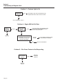
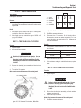
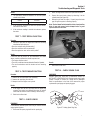
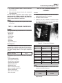
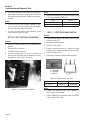
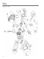
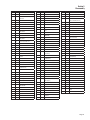
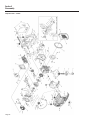
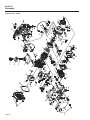
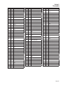
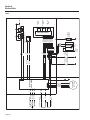
1
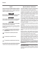
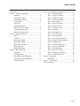
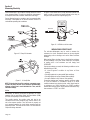
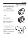
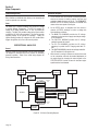
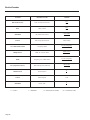
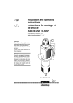
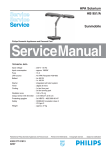
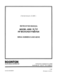
® Diagnostic Repair Manual iX Series Inverter models: iX800 iX1600 iX2000 Portable generators Foreword SAFETY Read This Manual Thoroughly Throughout this publication, DANGER, WARNING, and CAUTION blocks are used to alert the mechanic to special instructions concerning a particular service or operation that might be hazardous if performed incorrectly or carelessly. Observe them carefully. Their definitions are as follows: This SERVICE MANUAL has been written and published by Generac to aid our dealers' mechanics and company service personnel when servicing the products described herein. fter this heading, read instructions that, if not strictly complied A with, will result in serious personal injury, including death. fter this heading, read instructions that, if not strictly complied A with, could result in serious personal injury, including death. fter this heading, read instructions that, if not strictly complied A with, might result in minor or moderate injury. Four commonly used safety symbols accompany the DANGER, WARNING and CAUTION blocks. The type of information each indicates follows: if not followed, could endanger personal safety and/or This symbol points out important safety information that, property of others. This symbol points out potential explosion hazard. This symbol points out potential fire hazard. This symbol points out potential electrical shock hazard. These “Safety Alerts” alone cannot eliminate the hazards that they signal. Strict compliance with these special instructions plus “common sense” are major accident prevention measures. It is assumed that these personnel are familiar with the servicing procedures for these products, or like or similar products manufactured and marketed by Generac. That they have been trained in the recommended servicing procedures for these products, including the use of common hand tools and any special Generac tools or tools from other suppliers. Generac could not possibly know of and advise the service trade of all conceivable procedures by which a service might be performed and of the possible hazards and/or results of each method. We have not undertaken any such wide evaluation. Therefore, anyone who uses a procedure or tool not recommended by Generac must first satisfy themselves that neither his nor the products safety will be endangered by the service procedure selected. All information, illustrations and specifications in this manual are based on the latest product information available at the time of publication. When working on these products, remember that the electrical system and engine ignition system are capable of violent and damaging short circuits or severe electrical shocks. If you intend to perform work where electrical terminals could be grounded or touched, the battery cables should be disconnected at the battery. Any time the intake or exhaust openings of the engine are exposed during service, they should be covered to prevent accidental entry of foreign material. Entry of such materials will result in extensive damage when the engine Is started. During any maintenance procedure, replacement fasteners must have the same measurements and strength as the fasteners that were removed. Metric bolts and nuts have numbers that indicate their strength. Customary bolts use radial lines to indicate strength while most customary nuts do not have strength markings. Mismatched or incorrect fasteners can cause damage, malfunction and possible injury. NOTE: Special NOTES appear in bold type throughout this publication. While not pertaining to safety, they emphasize procedures, circumstances or specifications that require special attention. REPLACEMENT PARTS When servicing this equipment, it is extremely important that all components be properly installed and tightened. If improperly installed and tightened, sparks could ignite fuel vapors from fuel system leaks. Table of Contents Specifications...................................................................... 2 Section 4 – Troubleshooting and Diagnostic Tests.............. 15 Section 1 – Generator Fundamentals.................................... 6 Test 1 – Check Engine RPM................................... 19 Magnetism.............................................................. 6 Test 2 – Test Sub Coil of Stator.............................. 19 Electromagnetic Fields............................................. 6 Test 3 – Test Main Coil of Stator............................. 19 Electromagnetic Induction........................................ 6 Test 4 – Test DC Circuit Breaker............................. 20 Electrical Units......................................................... 6 Test 5 – Test DC Rectifier....................................... 20 Ohm's Law.............................................................. 7 Test 6 – Test DC Coil on Stator............................... 20 A Simple AC Generator............................................ 7 Test 7 – Test Recoil Function.................................. 21 What is an “iX” Inverter Unit?................................... 8 Test 8 – Test Engine Function................................. 21 iX Inverter System Overview.................................... 8 Test 9 – Check Spark............................................. 21 Why Variable Speed Control?................................... 8 Test 10 – Check Spark Plug................................... 21 Section 2 – Measuring Electricity......................................... 9 Test 11 – Check Fuel Pump.................................... 22 Meters..................................................................... 9 Test 12 – Check Carburetion.................................. 22 The VOM................................................................. 9 Test 13 – Check Engine Compression.................... 23 Measuring AC Voltage.............................................. 9 Test 14 – Test Ignition Trigger Assembly................. 23 Measuring DC Voltage.............................................. 9 Test 15 – Test Ignition Coil..................................... 24 Measuring AC Frequency......................................... 9 Test 16 – Test Fuel Shutoff Switch.......................... 24 Measuring Current................................................... 9 Test 17 – Check Choke Assembly.......................... 25 Measuring Resistance............................................ 10 Test 18 – Test Stepper Motor................................. 25 Section 3 – Major Components.......................................... 11 Test 19 – Test Oil Level Switch............................... 25 Introduction........................................................... 11 Test 20 – Test Ignition Coil Winding........................ 26 UNIT Identification................................................. 11 Test 21 – Test FlexPower Switch............................ 26 Internal Major Engine Components......................... 12 Section 5 – Disassembly................................................... 27 Internal Major Electrical Components..................... 13 Disassembly.......................................................... 27 Operational Analysis.............................................. 14 Section 6 – Electrical Data................................................. 36 Electrical Formulas............................................................ 38 Page 1 Specifications – iX800 A H M Internal - Not Shown Receptacles A 2x5-15R Circuit Breakers M Internal Overload Protection Other Features H FlexPower Recommended Oil S A E 30 1 0 W-30 S y n t he ti c 5 W-3 0 Page 2 Product Series iX800 A/C Rated Output Watts: 800 A/C Maximum Output Watts: 850 A/C Voltage 120 A/C Frequency 60 Rated 120 VAC Amperage 6.6 Max 120 VAC Amperage 7.0 Engine Displacement 38cc Engine Type 4-stroke OHV FlexPower Yes Low Oil Shutdown Method Level Fuel Tank Capacity (Gal) 0.5 Run Time at 50% (Hours) 3.6 Length (L) 18 inches Width (W) 10 inches Height (H) 15 inches Unit Weight – Dry (lbs) 29 Spark Plug Type NGK CR7HSA Spark Plug Gap 0.030 inch Oil Capacity 0.18 qt. Specifications – iX1600 Product Series iX1600 A/C Rated Output Watts 1600 A/C Maximum Output Watts 1650 A/C Voltage 120 A/C Frequency 60 Rated 120 VAC Amperage 13.3 Max 120 VAC Amperage 13.75 Engine Displacement 99cc Engine Type 4-stroke OHV FlexPower Yes Low Oil Shutdown Method Level Fuel Tank Capacity (Gal) 0.8 Run Time at 50% (Hours) 4.9 Length (L) 21 inches Width (W) 11 inches Height (H) 18 inches Unit Weight – Dry (lbs) 43.5 Spark Plug Type NGK BPR7HS Spark Plug Gap 0.030 inch Oil Capacity 0.63 qt. B A H M Internal - Not Shown Receptacles A 2x5-15R B 1x12VDC Circuit Breakers M AC Internal Overload Protection DC 5 Amp Circuit Breaker Other Features H FlexPower Recommended Oil SAE 30 10W- 30 S y nt het ic 5W- 30 Page 3 Specifications – iX2000 Product Series iX2000 A/C Rated Output Watts: 2000 A/C Maximum Output Watts: 2200 A/C Voltage 120 A/C Frequency 60 Rated 120 VAC Amperage 16.6 Max 120 VAC Amperage 18.3 Engine Displacement 126cc Engine Type 4-stroke OHV FlexPower Yes Low Oil Shutdown Method Level Fuel Tank Capacity (Gal) 1.0 Run Time at 50% (Hours) 4.7 Length (L) 22 inches Width (W) 12 inches Height (H) 18 inches Unit Weight – Dry (lbs) 50 Spark Plug Type NGK BPR6ES Spark Plug Gap 0.030 inch Oil Capacity 0.63 qt. B A H M Internal - Not Shown Receptacles A (2) 5-20R 120V B 1x12VDC Circuit Breakers M AC Internal Overload Protection DC 5 Amp Circuit Breaker Other Features H FlexPower Recommended Oil S A E 30 10W- 30 S y nt het ic 5W- 30 Page 4 NOTES Page 5 Section 1 Generator Fundamentals Magnetism Magnetism can be used to produce electricity and electricity can be used to produce magnetism. Much about magnetism cannot be explained by our present knowledge. However, there are certain patterns of behavior that are known. Application of these behavior patterns has led to the development of generators, motors and numerous other devices that utilize magnetism to produce and use electrical energy. See Figure 1. The space surrounding a magnet is permeated by magnetic lines of force called “flux”. These lines of force are concentrated at the magnet's north and south poles. They are directed away from the magnet at its north pole, travel in a loop and re-enter the magnet at its south pole. The lines of force form definite patterns which vary in intensity depending on the strength of the magnet. The lines of force never cross one another. The area surrounding a magnet in which its lines of force are effective is called a “magnetic field”. Like poles of a magnet repel each other, while unlike poles attract each other. Figure 2. The Right Hand Rule Electromagnetic Induction An electromotive force (EMF) or voltage can be produced in a conductor by moving the conductor so that it cuts across the lines of force of a magnetic field. Similarly, if the magnetic lines of force are moved so that they cut across a conductor, an EMF (voltage) will be produced in the conductor. This is the basic principal of the revolving field generator. Figure 3, below, illustrates a simple revolving field generator. The permanent magnet (Rotor) is rotated so that its lines of magnetic force cut across a coil of wires called a Stator. A voltage is then induced into the Stator windings. If the Stator circuit is completed by connecting a load (such as a light bulb), current will flow in the circuit and the bulb will light. Figure 1. Magnetic Lines of Force Electromagnetic Fields All conductors through which an electric current is flowing have a magnetic field surrounding them. This field is always at right angles to the conductor. If a compass is placed near the conductor, the compass needle will move to a right angle with the conductor. The following rules apply: • The greater the current flow through the conductor, the stronger the magnetic field around the conductor. • The increase in the number of lines of force is directly proportional to the increase in current flow and the field is distributed along the full length of the conductor. • The direction of the lines of force around a conductor can be determined by what is called the “right hand rule”. To apply this rule, place your right hand around the conductor with the thumb pointing in the direction of current flow. The fingers will then be pointing in the direction of the lines of force. NOTE: The “right hand rule” is based on the “current flow” theory which assumes that current flows from positive to negative. This is opposite the “electron” theory, which states that current flows from negative to positive. Page 6 Figure 3. A Simple Revolving Field Generator Electrical Units AMPERE The rate of electron flow in a circuit is represented by the AMPERE. The ampere is the number of electrons flowing past a given point at a given time. One AMPERE is equal to just slightly more than 6.25 x 10¹⁸ electrons per second. Section 1 Generator Fundamentals With alternating current (AC), the electrons flow first in one direction, then reverse and move in the opposite direction. They will repeat this cycle at regular intervals. A wave diagram, called a “sine wave” shows that current goes from zero to maximum positive value, then reverses and goes from zero to maximum negative value. Two reversals of current flow is called a cycle. The number of cycles per second is called frequency and is usually stated in “Hertz”. A definite and exact relationship exists between VOLTS, OHMS and AMPERES. The value of one can be calculated when the value of the other two are known. Ohm's Law states that in any circuit the current will increase when voltage increases but resistance remains the same, and current will decrease when resistance Increases and voltage remains the same. VOLT AMPERES = The VOLT is the unit used to measure electrical PRESSURE, or the difference in electrical potential that causes electrons to flow. Very few electrons will flow when voltage is weak. More electrons will flow as voltage becomes stronger. VOLTAGE may be considered to be a state of unbalance and current flow as an attempt to regain balance. One volt is the amount of EMF that will cause a current of 1 ampere to flow through 1 ohm of resistance. Conductor of a Circuit OHM - Unit measuring resistance or opposition to flow - + AMPERE - Unit measuring rate of current flow (number of electrons past a given point) VOLT - Unit measuring force or difference in potential causing current flow If AMPERES is unknown while VOLTS and OHMS are known, use the following formula: VOLTS OHMS If VOLTS is unknown while AMPERES and OHMS are known, use the following formula: VOLTS = AMPERES x OHMS If OHMS is unknown but VOLTS and AMPERES are known, use the following: = OHMS VOLTS AMPERES A Simple AC Generator Figure 6 shows a very simple AC Generator. The generator consists of a rotating magnetic field called a ROTOR and a stationary coil of wire called a STATOR. The ROTOR is a permanent magnet which consists of a SOUTH magnetic pole and a NORTH magnetic pole. Figure 4. Electrical Units OHM The OHM is the unit of RESISTANCE. In every circuit there is a natural resistance or opposition to the flow of electrons. When an EMF is applied to a complete circuit, the electrons are forced to flow in a single direction rather than their free or orbiting pattern. The resistance of a conductor depends on (a) its physical makeup, (b) its cross-sectional area, (c) its length, and (d) its temperature. As the conductor's temperature increases, its resistance increases in direct proportion. One (1) ohm of resistance will permit one (1) ampere of current to flow when one (1) volt of electromotive force (EMF) is applied. STATOR ROTOR MAGNETIC FIELD Ohm's Law VOLTS (E) AMPS (I) OHMS (R) Figure 5. Ohm's Law Figure 6. A Simple AC Generator As the MOTOR turns, its magnetic field cuts across the stationary STATOR. A voltage is induced into the STATOR windings. When the magnet's NORTH pole passes the STATOR, current flows in one direction. Current flows in the opposite direction when the magnet's SOUTH pole passes the STATOR. This constant reversal of current flow results in an alternating current (AC) waveform that can be diagrammed as shown in Figure 7. The ROTOR may be a 2-pole type having a single NORTH and a single SOUTH magnetic pole. The 2-pole ROTOR must be turned at 3600 rpm to produce an AC frequency of 60 Hertz. Page 7 Section 1 Generator Fundamentals CURRENT VOLTAGE (+) 0 180 360 (-) ONE CYCLE Figure 7. Alternating Current Sine Wave 3. AC voltage is delivered to the Inverter Assembly from the Stator which maintains voltage to the 120 VAC receptacles. 4. AC voltage is delivered to the bridge rectifier from the DC Charge Coil for the 12VDC outlet available for battery charging (if equipped). 5. AC voltage is delivered to the Inverter Assembly from the sub coil for inverter operation. 6. AC voltage is delivered to the LED module for ignition spark to the magneto. What is an “iX” Inverter Unit? The iX portable is a computer controlled generator that uses an inverter to create a superior sine wave and maintain a steady frequency. These units are different from conventional generators in that the performance of the engine and AC generator are more accurately matched over a wide range of power needs. The iX computer controlled generator provides greater efficiency of both the engine and the generator while maintaining electrical output within an acceptable voltage range. The frequency is controlled by the inverter and is maintained at a steady 60 Hz signal throughout the load range. Computer controlled generator units have the ability to operate the engine over a wide range of speeds while conventional generators will deliver correct AC frequency and voltage only at a fixed RPM. Unlike conventional AC generators, the iX unit can match engine speed to load requirements. This provides several advantages, as follows. • Smaller engines can be used to produce more power than on a conventional generator, since they can be allowed to run at a higher speed. • When the load is reduced, the engine can run at slower than the conventional speeds. This improves fuel economy and reduces engine noise. • The iX unit can be operated closer to its peak power point at all times, because output voltage and current are a function of engine speed. This allows for a much more compact generator design. Why Variable Speed Control? Most electrical loads will operate satisfactorily only within a relatively small voltage band. In order to provide useful voltage at larger load currents, it is necessary to increase engine speed. In conventional AC generators, some form of voltage regulation is needed to provide correct voltage in the full range of load current. This is often accomplished by regulating excitation current to the Rotor (field) which then regulates the strength of the Rotor’s magnetic field. The voltage induced into the Stator windings is proportional to the strength of the Rotor’s magnetic field. The iX inverter generators use a Rotor having a fixed, permanent magnetic field. The strength of this magnetic field is fixed and cannot be regulated. The output voltage of an iX inverter will tend to droop with increasing electrical loads. The inverter maintains a constant AC output voltage by increasing engine and Rotor speed as the load current increases to offset this inherent voltage droop. LED MODULE IGNITION WINDING BRIDGE RECTIFIER DC CHARGE WINDING ENGINE ROTOR STATOR MAIN WINDING SUB COIL WINDING INVERTOR MODULE iX Inverter System Overview Figure 8 is a block diagram of the iX system. The major elements of the system are represented in the diagram. Operation of the system may be described briefly as follows: 1. The engine is directly coupled to a permanent magnet type Rotor, so the Rotor runs at the same speed as the engine. 2. As the Rotor turns, its magnetic field cuts across the Stator windings to induce a voltage into the Stator. Page 8 STEPPER MOTOR Figure 8. Inverter Block Diagram Section 2 Measuring Electricity Meters Devices used to measure electrical properties are called meters. Meters are available that allow one to measure (a) AC voltage, (b) DC voltage, (c) AC frequency, and (d) resistance in ohms. The following apply: • To measure AC voltage, use an AC voltmeter. • To measure DC voltage, use a DC voltmeter. • Use a frequency meter to measure AC frequency in “Hertz” or “cycles per second”. • Use an ohmmeter to read circuit resistance, in “Ohms”. The VOM 1. Always read the generator's AC output voltage only at the unit's rated operating speed and AC frequency. 2. The generator's Voltage Regulator can be adjusted for correct output voltage only while the unit is operating at its correct rated speed and frequency. 3. Only an AC voltmeter may be used to measure AC voltage. DO NOT USE A DC VOLTMETER FOR THIS PURPOSE. *DANGEROUS VOLTAGES. CONTACT WITH HIGH VOLTAGE DANGER! GENERATORS PRODUCE HIGH AND TERMINALS WILL RESULT IN DANGEROUS AND POSSIBLY LETHAL ELECTRICAL SHOCK. A meter that will permit both voltage and resistance to be read is the “volt-ohm-milliammeter” or “VOM”. Some VOMs are of the “analog” type (not shown). These meters display the value being measured by physically deflecting a needle across a graduated scale. The scale used must be interpreted by the user. “Digital” VOMs (Figure 9) are also available and are generally very accurate. Digital meters display the measured values directly by converting the values to numbers. NOTE: Standard AC voltmeters react to the AVERAGE value of alternating current. When working with AC, the effective value is used. For that reason a different scale is used on an AC voltmeter. The scale is marked with the effective or “rms” value even though the meter actually reacts to the average value. That is why the AC voltmeter will give an incorrect reading if used to measure direct current (DC). Measuring DC Voltage A DC voltmeter or a VOM may be used to measure DC voltages. Always observe the following rules: 1. Always observe correct DC polarity. a. Some VOMs may be equipped with a polarity switch. b. On meters that do not have a polarity switch, DC polarity must be reversed by reversing the test leads. 2. Before reading a DC voltage, always set the meter to a higher voltage scale than the anticipated reading. If in doubt, start at the highest scale and adjust the scale downward until correct readings are obtained. 3. The design of some meters is based on the “current flow” theory while others are based on the “electron flow” theory. a. The “current flow” theory assumes that direct current flows from the positive (+) to the negative (-). b. The “electron flow” theory assumes that current flows from negative (-) to positive (+). NOTE: When testing generators, the “current flow” theory is applied. That is, current is assumed to flow from positive (+) to negative (-). Measuring AC Frequency VOM’s may also measure the frequency of an AC voltage (if equipped). The iX Inverter will produce AC frequencies that are exactly 60Hz. Since the inverter module controls the frequency, their will not be any direct relation to the speed of the engine and the output of the unit. Measuring Current Figure 9. Digital VOM Clamp-on Measuring AC Voltage An accurate AC voltmeter or a VOM may be used to read the generator's AC output voltage. The following apply: To read the current flow, in AMPERES, a clamp-on ammeter may be used. This type of meter indicates current flow through a conductor by measuring the strength of the magnetic field around that conductor. The meter consists essentially of a current transformer with a split core and a rectifier type instrument connected to the secondary. The primary of the Page 9 Section 2 Measuring Electricity current transformer is the conductor through which the current to be measured flows. The split core allows the instrument to be clamped around the conductor without disconnecting it. In Figure 12 the control wire to a relay has been removed. The meter is used to connect and supply voltage to the relay to energize it and measure the amperes going to it. Current flowing through a conductor may be measured safely and easily. A line-splitter can be used to measure current in a cord without separating the conductors. 1.00 A BATTERY - + RELAY Figure 12. A VOM as an In-line meter Measuring Resistance Figure 10. Clamp-On Ammeter The volt-ohm-milliammeter may be used to measure the resistance in a circuit. Resistance values can be very valuable when testing coils or windings, such as the Stator and Rotor windings. When testing Stator windings, keep in mind that the resistance of these windings is very low. Some meters are not capable of reading such a low resistance and will simply read CONTINUITY. Figure 11. A Line-Splitter NOTE: If the physical size of the conductor or ammeter capacity does not permit all lines to be measured simultaneously, measure current flow in each individual line. Then, add the individual readings. In-Line Alternatively, to read the current flow in AMPERES, an in-line ammeter may be used. Most Digital Volt Ohm Meters (VOM) will have the capability to measure amperes. This usually requires the positive meter test lead to be connected to the correct amperes plug, and the meter to be set to the amperes position. Once the meter is properly set up to measure amperes the circuit being measured must be physically broken. The meter will be in-line or in series with the component being measured. Page 10 If proper procedures are used, the following conditions can be detected using a VOM: • A “shor t-to-ground” condition in any Stator or Rotor winding. • Shorting together of any two parallel Stator windings. • Shorting together of any two isolated Stator windings. • An open condition in any Stator or Rotor winding. Component testing may require a specific resistance value or a test for INFINITY or CONTINUITY. Infinity is an OPEN condition between two electrical points, which would read as no resistance on a VOM. Continuity is a CLOSED condition between two electrical points, which would be indicated as very low resistance or “ZERO” on a VOM. Section 3 Major Components Introduction The unit components and the major internal components of the generator are discussed in this section. Unit identification is broken down into two basic categories; items located that are visual from the outside and items located on the electrical control panel. The internal major components are grouped into two separate categories; mechanical and engine related items and electrical items. 20. Ground (Earth) Connection Lug: Grounding point for the generator; consult state and local electrical codes before use (floating ground). 21. 120 VAC Receptacles: Two (2) receptacles for connecting accessories. 1 13 5 4 1. Carrying Handle: Lift the generator by this handle only. 2 4 3 UNIT Identification 2 5 2. Spark Plug Cover: Allows access to the engine spark plug. 3. Fuel System Primer: Used to prime the fuel system for starting. 4. Fuel Cap Pressure Valve: Allows air to enter the fuel tank to equalize pressure. 6 5. Fuel Tank Cap: Access to fuel tank for filling. 6. Control Panel: location of generator controls and output receptacles. 7 6 7 7. Air Intake Slats: Allows for cooling air to enter the housing. 8 8. Muffler: Lowers engine exhaust noise. 9. Choke: Cold engine starting aid 13 8 10. Left Side Service Cover: Allows access to air filter, fuel filter and oil fill. 11. Vent Hoses: Allow venting of the carburetor. 12 12. Fuel Shutoff: Controls fuel supply to the carburetor. 11 13. Starter Rope: Pull rope for starting engine. 10 911 Control Panel 10 9 Figure 13. Unit Identification 14. Low Oil Level LED (yellow): Lights up when oil level is below safe operating level and the engine shuts down. 15. Overload LED (red): Lights up if the generator experiences a load greater than the rated output, low voltage, overheats or the powered circuit experiences a short. TheiX1600 output is iX2000 stopped even though the engine keeps running. 14 16. Ready LED (green): Indicates output from the generator unless there is a low oil or overload condition. 15 17. 12 VDC Plug (if equipped): Connection for re-charging 16 12VDC automotive-style batteries while generator is in operation. iX1600 iX2000 iX800 14 iX800 16 15 16 15 16 15 14 14 17 17 18. FlexPower™ Switch: This switch slows the engine speed when the load is reduced to save fuel and engine wear. 18 18 19. 12 VDC Circuit Breaker (if equipped): Overload protection for the 12 VDC charging system. 19 20 19 20Figure 21 14.21Control Panel Identification Page 11 Section 3 Major Components Internal Major Engine Components Engine A 4 stroke engine attached to the rotor creates the mechanical energy necessary to maintain current flow at the receptacles. Ignition Coil The ignition coil provides spark for the engine. Spark timing is determined by LED module and the Trigger Assembly (Hall Effect Sensor). Ignition Shutoff Switch The ignition shutoff switch is mechanically connected to the fuel shutoff valve. The internal contacts of the ignition shutoff switch are open when the fuel shutoff valve is in its ON position. The contacts are closed when the fuel shutoff valve is in its OFF position. When the contacts are closed it completes a path to ground to the LED module that will inhibit spark and shutdown the engine. IGNITION SHUTOFF SWITCH IGNITION COIL Figure 17. Low Oil Level Switch Figure 15. Ignition Coil The low oil level switch is a float type switch located inside the engine on the bottom of the crank case casting. When the internal contact is closed it completes a path to ground to the LED module that will inhibit spark and shutdown the engine. Trigger Assembly (Hall Effect Sensor) The trigger assembly is located directly underneath the stator. The stator sends timing pulses to the trigger assembly, depending on the position of the engine, to determine the correct timing for spark. This voltage is delivered to the LED module. SWITCH OPEN SWITCH CLOSED Figure 18. Carburetor TRIGGER ASSEMBLY Figure 16. The Trigger Assembly Page 12 The carburetor provides a sufficient air/fuel mixture to the engine to maintain the required speed. A stepper motor incorporated in the carburetor allows the engine to run at variable speeds. The speed of the engine is maintained by the inverter which will increase or decrease speed to maintain the output current necessary for loads. Section 3 Major Components Fuel Pump The mechanical fuel pump is located on the exterior of the plastic housing around the engine and is accessible by removing the side panels. Changes in pressure from the crankcase actuates a diaphragm inside the pump which then supplies fuel to the carburetor. STEPPER MOTOR INVERTER CARBURETOR FUEL PUMP Figure 19. Stepper Motor The Stepper Motor consists of a motor along with a gear and cam arrangement which allows motor movement to change the engine carburetor throttle setting. The Motor is controlled by output signals from the inverter assembly, which calculates the number of steps the stepper needs to take and generates the required signals to the Motor. The inverter signals the Motor to actuate in response to changes in AC output voltage. Thus, in response to decreasing AC output voltages, the Motor will increase the throttle setting and engine speed will increase. Conversely, increasing AC output voltages will cause the Motor to decrease throttle setting and engine speed will decrease. Figure 20. LED Module The LED module receives inputs from the inverter assembly to monitor an Overload condition. It also illuminates the Green Ready light when unit is producing voltage and ready to accept load. An AC voltage is delivered to the module from the stator for firing of the ignition coil. The module determines when to deliver spark to the ignition coil by receiving timing pulses from the trigger assembly and fires the coil using the voltage from the stator winding. Recoil Assembly The recoil assembly connected directly to the crank shaft of the engine and allows the engine to spin over when pulled and reach a speed that allows the engine to maintain that speed. Internal Major Electrical Components Inverter Module The inverter module receives voltage from two windings in the stator and produces a sine wave where the voltage is 120 VAC and the frequency is 60 Hz. It is also responsible for maintaining the correct engine speed needed to maintain current flow to the connected loads. Figure 21. Page 13 Section 3 Major Components Permanent Magnet Rotor Operational Description Sixteen permanent magnets have been affixed to the Rotor. The Rotor and Hub are balanced at the factory as an assembly and must be replaced as an assembly. 1. The iX inverter units are computer controlled generators that use an inverter to create a superior sine wave and maintain a steady frequency of 60 Hz. The PERMANENT MAGNET ROTOR is directly coupled to the ENGINE and rotates at the same speed as the engine. Stator The stator has 4 separate windings that provide AC voltage to several different components. The DC Coil provides AC voltage to the bridge rectifier where 12 VDC is provided for charging. The Main Coil provides voltage to the inverter which provides the 120 VAC to the receptacles. The Sub Coil provides operating voltage to the Inverter for operation. Finally, the Ignition winding provides AC voltage to the LED module which triggers the ignition coil to fire at the correct position. Operational Analysis General Figure 22, below is a block diagram of the iX inverter generator. The diagram is intended only for the purpose of illustrating generator operation. Refer to the actual wiring diagram for wiring interconnections. 2. As the ROTOR turns, its magnetic field cuts across a number of STATOR windings, to induce a voltage into those windings as follows: a. The MAIN COIL WINDING provides the AC voltage necessary for the inverter to supply rated output voltage to the receptacles. b. The SUB COIL WINDING provides the AC voltage needed to operate the Inverter. c. The DC COIL WINDING provides the AC voltage necessary to provide the DC Charging outlet with 12 VDC. d. The IGNITION WINDING provides the voltage needed for the LED module to fire the ignition coil. 3. While the unit is running it continues to monitor the current on the receptacles and make the needed adjustments to the engine speed by changing the output signals to the STEPPER MOTOR to either increase or decrease engine speed based on load demand. TRIGGER ASSEMBLY LED MODULE OUTLET IGNITION COIL MAGNETIC FIELD IGNITION WINDING BRIDGE RECTIFIER DC CHARGE WINDING ENGINE ROTOR STATOR MAIN WINDING SUB COIL WINDING INVERTOR MODULE MAGNETIC FIELD STEPPER MOTOR Figure 22. iX Inverter Operating Diagram Page 14 OUTLETS Section 4 Troubleshooting and Diagnostic Tests Problem 1 – No AC Output IS THE OVERLOAD LIGHT ON WHILE ENGINE IS RUNNING? IS THE GREEN STATUS LIGHT ON WHILE ENGINE IS RUNNING? OFF ON REMOVE RECEPTACLE PANEL AND VERIFY CONNECTIONS OF RECEPTACLES AND WIRING OFF BAD BAD ON GO TO “PROBLEM 6” IS THE LOAD CONNECTED? GOOD TEST 1 – CHECK ENGINE RPM REPAIR OR REPLACE COMPONENT GOOD TEST 3 – TEST MAIN COIL OF STATOR TEST 2 – TEST SUBCOIL OF STATOR NO YES GOOD REPLACE INVERTER MODULE GOOD BAD REPLACE INVERTER MODULE DISCONNECT THE LOAD, THEN RESTART THE ENGINE AND CHECK THE AC OUTPUT AGAIN BAD CHECK HARNESS FOR GOOD CONNECTIONS GOOD BAD REPLACE STATOR REPAIR OR REPLACE WIRE Problem 2 – No DC Output TEST 1 – CHECK ENGINE RPM TEST 4 – CHECK THE DC CIRCUIT BREAKER GOOD REPLACE DC CIRCUIT BREAKER GO TO “PROBLEM 6” CHECK HARNESS FOR GOOD CONNECTIONS GOOD TEST 5 – TEST DC RECTIFIER GOOD BAD BAD BAD REPLACE STATOR GOOD GOOD BAD REPAIR OR REPLACE WIRE REPLACE DC RECTIFIER TEST 6 – TEST DC COIL ON STATOR BAD REPLACE INVERTER MODULE Page 15 Section 4 Troubleshooting and Diagnostic Tests Problem 3 – Overload Light is On IS THE LOAD CONNECTED? YES DISCONNECT THE LOAD, THEN RESTART THE ENGINE AND CHECK THE AC OUTPUT AGAIN NO GO TO “PROBLEM 1, TEST 2” Problem 4 – Engine Will Not Pull Start TEST 7 – TEST RECOIL FUNCTION BAD REPLACE GOOD TEST 8 – TEST ENGINE FUNCTION GOOD VISUALLY INSPECT FOR OBSTRUCTIONS THAT WOULD CAUSE BINDING OF THE RECOIL ONCE INSTALLED BAD VISUALLY INSPECT EXTERNAL COMPONENTS FOR A FAILURE THAT WOULD CAUSE THE ENGINE TO BE SIEZED AN INTERNAL ENGINE FAILURE HAS POSSIBLY OCCURRED NOTHING FOUND BAD REPLACE COMPONENT Problem 5 – Flex Power Feature is Not Responding TEST 21 – TEST FLEX POWER SWITCH BAD REPLACE SWITCH Page 16 GOOD REPLACE INVERTER MODULE Section 4 Troubleshooting and Diagnostic Tests Problem 6 – Engine Will Not Start CHECK FUEL QUALITY AND SUPPLY GOOD CHECK FUEL SHUTOFF VALVE BAD TEST 17 – CHECK CHOKE ASSEMBLY GOOD OFF GOOD TEST 9 – CHECK SPARK GOOD BAD BAD REPLENISH FUEL SUPPLY TURN ON TEST 15 – TEST IGNITION COIL GOOD TEST 14 – TEST TRIGGER ASSEMBLY GOOD BAD BAD GOOD REPLACE CHOKE TEST 16 – TEST FUEL SHUTOFF SWITCH OFF IS “LOW OIL” LIGHT ON? BAD ON REPLACE REPLACE IGNITION COIL GO TO “PROBLEM 8” GOOD CHECK OIL LEVEL BAD TEST 20 – TEST IGNITION WINDING GOOD BAD REPLENISH OIL REPLACE LED MODULE REPLACE STATOR REPAIR OR REPLACE TEST 10 – CHECK SPARK PLUG BAD GOOD TEST 13 – CHECK ENGINE COMPRESSION BAD GOOD GOOD REPLACE ENGINE TEST 12 – CHECK CARBURETOR GOOD TEST 11 – CHECK FUEL PUMP BAD BAD REPLACE CARBURETOR REPLACE FUEL PUMP CONTACT TECHNICAL SERVICE Page 17 Section 4 Troubleshooting and Diagnostic Tests Problem 7 – Engine Hunts / Erratic Idle or Will Not Come Up to Speed IS THE UNIT PRODUCING AC POWER? IS THE ENGINE RUNNING ERRATICALLY? YES TEST 17 – CHECK CHOKE ASSEMBLY YES NO NO GO TO “PROBLEM 1” REPLACE INVERTER MODULE GOOD TEST 18 – TEST STEPPER MOTOR TEST 11 – CHECK FUEL PUMP GOOD BAD BAD REPLACE CHOKE ASSEMBLY REPLACE FUEL PUMP TEST 12 – CHECK CARBURETOR TEST 9 – CHECK SPARK GOOD BAD BAD BAD – ENGINE MISS APPARENT REPLACE STEPPER MOTOR REPLACE CARBURETOR TEST 14 – TEST TRIGGER ASSEMBLY BAD REPLACE GOOD REPLACE LED MODULE GOOD TEST 15 – TEST IGNITION COIL BAD Problem 8 – Unit Shuts Down for Low Oil CHECK OIL LEVEL BAD REPLENISH OIL Page 18 GOOD TEST 20 – TEST OIL LEVEL SWITCH BAD REPLACE ENGINE GOOD REPLACE LED MODULE REPLACE IGNITION COIL GOOD Section 4 Troubleshooting and Diagnostic Tests Test 1 – Check Engine RPM Tools Required Small Engine Tachometer Procedure 1. With the engine running connect the engine tachometer according to the manufactures instructions and record the engine RPM. Results 1. If the engine rpm was 3000 ±200 rpm it is running within rated specs, refer back to flow chart. 2. If the engine rpm was outside the range of 3000 ±200 rpm, go to Problem 7. Test 2 – Test Sub Coil of Stator 1 – GRAY 2 – EMPTY 3 – ORANGE 4 – GRAY 5 – ORANGE 6 – ORANGE 2 3 4 5 6 Figure 24. C4 Connector Pin Locations, Male Side 5. Set VOM to measure resistance. 6. Disconnect the C4 connector. On the female side of the connector connect one meter test lead to Pin 1 and connect the other meter test lead to Pin 4. Measure and record the resistance. Results Procedure 1. Stop the engine. 1. The resistance measured between Pin 1 and Pin 4 should be as follows: 2. Drain the fuel from the tank. 1 asoline is highly flammable and explosive. You can G be burned or seriously injured when handling fuel. Keep heat, sparks, and flame away. Wipe up spills immediately. Be careful not to touch the muffler while it is HOT. 3. Remove the electrical box assembly and back window and upper enclosure half. 4. Take out the C4 connector. Note: Do not remove the harness of the control panel. C4 CONNECTOR iX 800 0.5 Ohms iX 1600 0.7 Ohms iX 2000 0.3 Ohms 2. If the resistance measured is between the specified values, refer back to flow chart. 3. If the resistance reading is outside the tolerance, replace stator. Test 3 – Test Main Coil of Stator Procedure 1. Stop the engine. 2. Drain the fuel from the tank. be burned or seriously injured when handling fuel. Gasoline is highly flammable and explosive. You can Keep heat, sparks, and flame away. Wipe up spills immediately. Be careful not to touch the muffler while it is HOT. 3. Remove the electrical box assembly and back window and upper enclosure half. 4. Take out the 6 pin connector Figure 23. C4 Connector Pin Locations, Male Side Note: Do not remove the harness of the control panel. 5. Set VOM to measure resistance. Page 19 Section 4 Troubleshooting and Diagnostic Tests 6. Disconnect the C4 connector. On the female side of the connector connect one meter test lead to Pin 3 and connect the other meter test lead Pin 5, measure and record the resistance. 7. Repeat Step 6 between the following test points: • Pin 3 and Pin 6 • Pin 6 and Pin 5 Results 1. The resistance measured between the all tests points should be as follows: iX 800 2.1 Ohms ± 0.3 Ohms iX 1600 TBA ± 0.3 Ohms iX 2000 2.5 Ohms ± 0.3 Ohms 2. If the resistance measured is within the specified values, refer back to flow chart. Results 1. If CONTINUITY is measured across the circuit breaker, refer back to flow chart. 2. If the circuit breaker reads open, replace the DC circuit breaker and re-test. Test 5 – Test DC Rectifier Procedure 1. With the electrical panel still exposed remove the wires on the DC rectifier and mark the location of each wire on the rectifier. 2. Set VOM to the Diode test feature (marked on most meters by the diode symbol ). 3. Connect the meter test leads according to the chart below and record the results. 3. If the resistance reading is outside the tolerance, replace the stator. 1 2 3 4 Test 4 – Test DC Circuit Breaker Procedure 1. Remove the electrical panel so that the DC circuit breaker is exposed and remove both wires from the breaker. Ensure that the breaker is reset from the front of the panel and is not tripped. (+) Test Lead (-) Test Lead 1 1 2 3 4 INFINITY INFINITY INFINITY INFINITY INFINITY 2. Set VOM to measure resistance. 2 CONTINUITY 3. Connect one meter test lead to one side of the breaker and the other meter test lead to the other side of the breaker and measure resistance. CONTINUITY should be measured. 3 CONTINUITY INFINITY 4 CONTINUITY CONTINUITY INFINITY CONTINUITY Results 1. If the meter indicated the correct readings at all test points refer back to flow chart. DC BREAKER 2. If the meter indicated any reading other than what was specified, replace the rectifier. Test 6 – Test DC Coil on Stator Procedure DC BRIDGE RECTIFIER 1. Locate the two white wires coming from the stator. One of them will be located on the DC circuit breaker and the other one will be located on the rectifier. 2. Set VOM to measure resistance. Figure 25. DC Breaker and DC Bridge Rectifier Page 20 3. Connect one meter lead to one wire and the other meter lead to the other wire. Measure and record the resistance. Section 4 Troubleshooting and Diagnostic Tests Results 2. Attach the high tension lead to the spark tester terminal. 1. The resistance measured between the all tests points should be as follows: 3. Ground the spark tester clamp by attaching it to the cylinder head (see Figure 26). iX 1600 0.2 Ohms iX 2000 0.3 Ohms 2. If the resistance measured is within the specified values, refer back to flow chart. 3. If the resistance reading is outside the tolerance, replace the stator. 4. Attempt to pull start the engine. If spark jumps the tester gap, the ignition system is working properly. Note: The fuel shutoff switch should be in the closed position Note: It may take several start attempts before a good spark is noticed in the tester Test 7 – Test Recoil Function Procedure 1. Attempt to pull start the engine and make the following observations while doing so. • Does the cord pull easily and smoothly? • Does the cord return with no assistance? • Does the engine turn over as the cord is pulled? Results If the recoil did not perform as the observations are stated above, possible problems that could be present are: • The engine could be seized. • The recoil could have become detached from the flywheel. • The recoil mechanism could be broken and not retracting properly. Test 8 – Test Engine Function Figure 26. Results 1. Refer back to flow chart Test 10 – Check Spark Plug Procedure PROCEDURE 1. Remove the recoil and front cover assembly. Remove spark plug. Clean with a commercial solvent. DO NOT BLAST CLEAN SPARK PLUG. Replace spark plug if badly fouled, if ceramic is cracked, or if badly worn or damaged. Refer to specifications in the front of this manual for proper replacement spark plugs and spark plug gaps. 2. Remove the spark plug from the unit. 3. Attempt to turn the engine over by hand. Results 1. If the engine can not turn over freely with the spark plug removed, the engine has suffered some type of internal failure that has seized it and is inhibiting it from running. 2. Refer back to flow chart. Test 9 – Check Spark PROCEDURE A commercially available spark tester may be used to test the engine ignition system. Figure 27. Setting Spark Plug Gap 1. Disconnect the spark plug lead from the spark plug. Page 21 Section 4 Troubleshooting and Diagnostic Tests NORMAL MISFIRES CARBURETOR FUEL PUMP PRE-IGNITION DETONATION Figure 28. Spark Plug Conditions RESULTS 1. Clean and regap or replace sparks plug as necessary. 2. Refer back to the Flow Chart. Test 11 – Check Fuel Pump Procedure 1. Open up the side panel that exposes the carburetor and fuel pump. 2. Carefully remove the fuel line from the filter on the inlet side of the carburetor. be burned or seriously injured when handling fuel. Gasoline is highly flammable and explosive. You can Keep heat, sparks, and flame away. Wipe up spills immediately. 3. Using a suitable container to catch fuel, slowly pull on the recoil cord and turn the engine over. Fuel should flow from the fuel line. If fuel does not flow, verify that fuel is available to the pump. If fuel is available to the pump inspect the fuel filter and pulse line. RESULTS 1. If fuel does not flow, replace the fuel pump. 2. If fuel flow has been verified proceed to Test 12. Page 22 Figure 29. Test 12 – Check Carburetion Before checking the carburetor, be sure the fuel tank has an ample supply of fresh, clean gasoline. Check that all shutoff valves are open and fuel flows freely through the fuel line. Make sure the choke operates properly. If the engine will not start, remove and inspect the spark plug. If the spark plug is wet, look for the following: • Over choking. • Excessively rich fuel mixture. • Water in fuel. • Intake valve stuck open. • Needle/float stuck open. If the spark plug is dry look for the following: • Leaking carburetor mounting gaskets. • Intake valve stuck closed. • Inoperative fuel pump. • Plugged fuel filter(s). • Varnished carburetor • Check that the choke is working properly. 1. Remove the fuel line at the carburetor and ensure that there is an adequate amount of fuel entering the carburetor. 2. Remove the float bowl and check to see if there is any foreign matter in the bottom of the bowl. 3. Remove the plastic float to gain access to the needle. 4. Remove the needle so it can be cleaned. Section 4 Troubleshooting and Diagnostic Tests 5. Use a suitable carburetor cleaner to clean the carburetor before reassembly. 6. After cleaning the carburetor, blow dry with compressed air and reassemble. Note: The shelf life of gasoline is about 30 days. Proper procedures need to be taken so that the fuel doesn’t varnish over time. A fuel stabilizer should be used at all times in order to ensure that the fuel stays fresh. RESULTS 1. If carburetor is varnished, clean or replace. Refer to back to Flow Chart. Test 14 – Test Ignition Trigger Assembly Procedure 1. Remove the electrical panel so that the LED module is exposed and disconnect the J1 connector. 2. Set VOM to measure resistance. 3. Locate Pin 3 on the J1 connector. Connect one meter test lead to Pin 3 and the other meter test lead to engine ground. Measure and record the resistance. Test 13 – Check Engine Compression Discussion Most engine problems may be classified as one or a combination of the following: • Will not start. • Starts hard. • Lack of power. • Runs rough. • Vibration. • Overheating. • High oil consumption. Figure 30. J1 Connector on LED Module Check Compression To check engine compression, remove the spark plug. Insert an automotive type compression gauge into the spark plug hole. Crank the engine until there is no further increase in pressure. The highest reading obtained is the engine compression pressure. Minimum allowable compression pressure cold engine 60 psi If compression is poor, look for one or more of the following causes: • Loose cylinder head bolts. • Failed cylinder head gasket. • Burned valves or valve seats. • Insufficient valve clearance. • Warped cylinder head. • Warped valve stem. • Worn or broken piston ring(s). • Worn or damaged cylinder bore. • Broken connecting rod. • Worn valve seats or valves. • Worn valve guides. Table 1. J1 Connector Pin Chart Location Function Pin 1 Ignition Coil Wire Color Blue Pin 2 Low Oil Switch Yellow Pin 3 Trigger Assembly White Pin 4 Ground Pink Pin 5 Ignition Winding Red Pin 6 Fuel Shutoff Switch Gray Pin 7 Inverter Purple Pin 8 Inverter Yellow Pin 9 Inverter White Pin 10 Inverter Green Results 1. If the meter reading is within ± 5 ohms of the correct resistance, refer back to flow chart. iX 800 30 Ohms iX 1600 30 Ohms iX 2000 129 Ohms 2. If the meter did not indicate the correct resistance, replace trigger assembly. Page 23 Section 4 Troubleshooting and Diagnostic Tests Test 15 – Test Ignition Coil Procedure 1. Open up the electrical panel so that the control panel wiring is exposed. 2. Disconnect the J1 connector and disconnect the ignition coil boot from the spark plug. 3. Set VOM to measure resistance. 4. Connect one meter test lead to ground and connect the other meter test lead to Pin 1 on the J1 connector. Measure and record the resistance. Figure 32. Figure 31. 5. Connect one meter test lead to the spark plug wire and connect the other meter test lead to engine ground. Measure and record the resistance. Results 1. Refer to the following chart. If the correct values were measured in Steps 4 and 5, refer back to flow chart. Pin 1 to Ground 1.7 Ohms ± 0.5 Ohms Spark Plug to Ground 12.5K Ohms ± 2K Ohms Test 16 – Test Fuel Shutoff Switch Procedure 1. Open up the electrical panel so that the control panel wiring is exposed. 2. Set fuel shutoff valve to the CLOSED position. 3. Disconnect the J1 connector from the LED module. 4. Set VOM to measure resistance. 5. Connect one-meter test lead to J1 Pin 6 and the other test lead to ground. Measure and record the resistance. 6. Set fuel shutoff valve to the OPEN position 2. If the incorrect values were measured in Steps 4 and 5, inspect ignition coil connector for bad connection. If the connection is verified good, replace ignition coil. 3. If the incorrect value was measured in Step 5 then inspect the ground connection on Pin 2 of the C2 connector going to the ignition coil. 7. Repeat Step 5. Fuel Shutoff Valve Position Fuel Shutoff Switch Reading CLOSED OPEN (INFINITY) OPEN CLOSED (CONTINUITY) Results 1. If INFINITY was measured when the shutoff valve was CLOSED, and CONTINUITY was indicated when the valve was OPEN, refer back to flow chart. 2. If CONTINUITY to ground was not measured when the valve was in the OPEN position, verify the mechanical Page 24 Section 4 Troubleshooting and Diagnostic Tests connection between the valve and the switch. mechanical connection is good, replace switch. If 3. If the meter read CONTINUITY when the shutoff valve was in either the open or closed position, verify mechanical connection between the valve and the switch. If mechanical connection is good replace shutoff switch. Note: A fuel shutoff switch that does not read INFINITY when the fuel shutoff valve is in the closed position will cause a no spark condition. Test 17 – Check Choke Assembly Procedure 1. If the generator is surging it may have a carburetion problem. A lean condition can cause erratic RPM. Slowly slide the choke to see if surging stops. If it does stop, carburetion should be checked. 2. Verify the mechanical connection to the carburetor and that the choke is functioning properly. Results 1. If the choke is functioning correctly, refer back to flow chart. 2. If the choke is not functioning correctly, replace the choke assembly. d. Pin 2 and Pin 3 – approximately 50 ohms should be measured. e. Pin 2 and Pin 4 – INFINITY should be measured. f. Pin 3 and Pin 4 – INFINITY should be measured. Results 1. If the values in steps 3a through 3f are good, refer back to flow chart. 2. If any one of the values in steps 3a through 3f tested bad, replace stepper motor. iX1600, iX2000 Procedure 1. Disconnect the C3 connector (Stepper motor) from the Inverter module. 2. Set VOM to measure resistance. 3. Connect a VOM test leads across the following test points a. Pin 1 to Pin measured. b. Pin 2 to Pin measured. c. Pin 3 to Pin measured. d. Pin 4 to Pin measured. 1 Test 18 – Test Stepper Motor iX800 Procedure 5 – approximately 195 ohms should be 5 – approximately 195 ohms should be 5 – approximately 195 ohms should be 2 3 1 – RED 2 – ORANGE 3 – WHITE 1. Disconnect the J2 connector (Stepper Motor) from the Inverter module. 2. Set VOM to measure resistance. 5 – approximately 195 ohms should be 4 5 4 – YELLOW 5 – BLUE Figure 34. C3 Connector Female Side, iX1600, iX2000 Results 1 – PINK 2 – YELLOW 3 – BLUE 4 – ORANGE 1 2 3 4 Figure 33. C3 Connector Female Side, iX800 3. Connect VOM test leads across the following test points: a. Pin 1 and Pin 4 – approximately 50 ohms should be measured. b. Pin 1 and Pin 3 – INFINITY should be measured. c. Pin 1 and Pin 2 – INFINITY should be measured. 1. If the values in steps 3a through 3d are good, refer back to flow chart. 2. If any one of the values in steps 3a through 3d tested bad, replace stepper motor. Test 19 – Test Oil Level Switch Procedure 1. Verify that the engine is filled with the appropriate amount of oil. 2. Locate the low oil shutdown wire on the engine and isolate it from the rest of the harness. 3. Set VOM to measure resistance. Page 25 Section 4 Troubleshooting and Diagnostic Tests 4. Connect one meter lead to the wire that runs through the plastic engine housing to the oil level switch and the other test lead to engine frame ground. Measure and record the resistance. Results 1. Refer to the following chart. If the meter reading is within ± 0.2 ohms, refer back to flow chart. Results iX 800 0.8 Ohms iX 1600 0.5 Ohms 1. If oil level was good and the meter indicated an open circuit, check for a short to ground on the wire between the low oil level switch and the LED module. iX 2000 0.7 Ohms 2. If oil level was good and the meter indicated a closed circuit to ground, replace the engine. Test 21 – Test FlexPower Switch Procedure Test 20 – Test Ignition Coil Winding Procedure 1. Remove the electrical panel so the components are exposed. 2. Disconnect the J1 Connector. 3. Set VOM to measure resistance. 4. Connect one meter lead to Pin 5 of the J1 connector and the other meter test lead to ground. Measure and record the resistance. Refer to Table 1 on Page 23. 1. Disconnect the orange and brown wires from the FlexPower switch (FPS). 2. Set VOM to measure resistance. 3. Set FPS to “ECO” position. 4. Connect one meter test lead to Pin 1 and the other meter test lead to Pin 2. Measure resistance and record results. 5. Set FPS to “HIGH” position. 6. Repeat Step 4. Measure resistance and record results. 3 1 2 1 – ORANGE 2 – BROWN 3 – EMPTY Figure 36. FlexPower Switch Test Points Test Points Pin 1 to Pin 2 Figure 35. J1 Connector on LED Module ECO HIGH INFINITY CONTINUITY Results 1. If INFINITY was measured in Step 4 and CONTINUITY in Step 5, replace inverter module. 2. If either CONTINUITY was measured in Step 4 or INFINITY in Step 5, replace FPS switch. Page 26 Section 5 Disassembly Discussion During the process of tearing the unit apart it is critical to make special notes as to the way the different parts are located inside. There is no room for error when putting the unit back together. When re-assembling the unit, it is good to be proactive and always thinking about the next step to eliminate back tracking. It is also a good idea to continually re-check what parts are left for reassembly to ensure that no parts are forgotten during the process. Disassembly Muffler Removal 1. Drain all fuel and oil from unit. 2. Remove four (4) Phillips screws located on the black exhaust cover. Figure 38. 3. Remove the rubber muffler gasket and note orientation of the seal before removing. 5. Remove the retaining clip underneath the fuel fill cap cover. Enclosure Removal 4. Remove one (1) flat head screw holding the service access panel. Figure 39. 6. Remove four (4) Phillips screws holding the control panel to the housing. Figure 37. The following items are able to be serviced and replaced at this point: • Fuel Pump • Stepper Motor • Carburetor • Air Filter Figure 40. Page 27 Section 5 Disassembly 7. Disconnect the connectors and ground wires and remove control panel. 8. Remove one (1) Phillips screw to remove the fuel shutoff knob. 9. Remove one (1) Phillips screw from recoil access area. 10. Remove three (3) Phillips screws located on the handle. (two on iX 800) 11. Carefully orient the assembly so that the side with the access cover is facing down. See Figure 38. 12. Remove two (2) Phillips bolts on the underside of the plastic housing. 13. The side with the spark plug access should be facing up at this point, remove this half of the enclosure. • Lower and Upper Enclosures • Ignition Coil • Recoil Assembly Engine Housing Removal 19. Remove one (1) Phillips screw from the fuel pump housing. 20. Remove two (2) 8 mm nuts from the carburetor plastic intake assembly and remove the fuel pump and the carburetor as one assembly and isolate the fuel hose from the fuel shutoff valve. Note: Keep the two spacers with the housing once it has been removed. 21. Remove ten (10) Phillips screws around the top and bottom seams of the housing. There are two different sizes of screws. Make note of which one is which for reassembly. 22. Isolate the wiring harness from the housing and remove the low oil plug and pull the wire through for removal. 23. Separate the two housings to expose the engine. Figure 41. 14. Disconnect the fuel tank by removing the hose clamp and removing the hose from fuel shutoff valve. 15. Remove one (1) Phillips screw from the fuel shutoff valve so it is isolated from the enclosure. Note: Make note of the orientation of the fuel shutoff valve for re-assembly. 16. On the iX 1400, iX 1600 and iX 2000 disconnect connectors and remove inver ter. On the iX 800 the inverter is connected to the fuel shutoff switch and can not be removed. 17. Feed the recoil cord through the lower enclosure piece. 18. The engine assembly should be able to be lifted out of the unit and set aside. Time to reach this point: 15 minutes The following items are able to be serviced and replaced at this point • Inverter Assembly • Fuel Shutoff Valve • Fuel Shutoff Switch Page 28 Figure 42. Time to reach this point: 25 minutes The following items are able to be serviced at this point • Engine • Rotor • Stator • Low Oil Switch • Fan • Trigger Assembly The following items are able to be replaced at this point • Low Oil Switch • Trigger Assembly Section 5 Disassembly Rotor/Stator Removal 24. Remove the 8mm bolt in the center of the recoil jaw. Figure 45. Figure 43. 25. Remove two 8mm bolts from the starting jaw seat. 26. Remove the fan. 27. Remove the 15mm nut in the center of the rotor by inserting the socket wrench first and install a steering wheel puller over the socket wrench as shown in Figure 41. Use an adjustable wrench to counter the torque from the socket to break the nut free. 29. Remove two (2) 8mm bolts holding stator to engine casting. 30. Remove stator. • Time to reach this point: 45 minutes • The following items are able to be replaced at this point • Engine • Stator • Rotor Reassembly Notes • The above procedure should be reversed to re-assemble unit • Order of reassembly 1. Engine 2. Stator 3. Rotor 4. Engine Housing 5. Fuel Pump 6. Carburetor 7. Place Engine Housing in lower Enclosure Note: Be sure to locate all harnesses and fuel lines to ensure they will not be obstructed during the reassembly process. The stepper motor harness must be able to reach the inverter 8. Fuel Shutoff Switch Note: Test Fuel Switch for correct orientation before putting the two halves together. 9. Fuel Tank Figure 44. 28. With the nut removed install the steering puller with the center bolt tight against the center shaft and remove the rotor assembly 10. Inverter 11. Upper Enclosure 12. Retaining Clip below fuel cap 13. Receptacle panel Page 29 Section 5 Disassembly Exploded View – iX800 Page 30 Section 5 Disassembly ITEM QTY. DESCRIPTION ITEM QTY. DESCRIPTION ITEM QTY. DESCRIPTION 1 1 ENGINE ASSY. 39 2 DAMPING RING, POTHOOK 80 3 SCREW, M4X12 2 1 SUPERCHARGED CAP ASSY, FUEL TANK 40 2 STUD BOLT 81 1 CASING, ENGINE UPPER 41 1 GASKET, POTHOOK 82 4 42 1 POTHOOK SCREW, TAPPING, CROSS, RECSD, P/HEAD(ST4.2X13) 43 2 PIN, HOLLOW FIXED POSITION 83 1 PUMP ASSY. FUEL 84 1 GASPIPE, FUEL PUMP 85 1 OUTLET PIPE, FUEL PUMP 86 1 SCREW, PHILIPS, ST4.8X19 87 1 SHELL, LOWER 3 1 FUEL FILLER INLET RUBBER RING 4 8 CLAMP, FUEL HOSE 5 1 CUP, FUEL FILTER 6 1 TANK, FUEL 7 4 SHOCK ABSORBER BLOCK 8 2 SCREW, CROSS RECESSED PAN HEAD, M6X120 9 1 COVER, UPPER SHELL 10 1 SHELL, UPPER 11 2 SCREW, CROSS RECESSED PAN HEAD, M6X14 12 8 LOCK SLICE/SCREW CLIP 13 2 ALIGNMENT PIN 14 4 FEET, VIBRATION MOUNTS 15 4 BOLT, HEX, FLANGE FACE (M6X12) 16 1 LOWER CASING, ENGINE 17 2 BOLT, HEX, FLANGE FACE (M5X16) 18 4 WASHER 19 4 SLEEVE, DAMPING/VIBRATION MOUNTS 20 1 44 1 BLOCK, CARBURETOR CUSHION 45 2 SEAL GASKET, CARBURETOR (IN) 46 1 CARBURETOR REGULATING ASSY. 47 1 SEAL GASKET, CARBURETOR (IN) 88 1 SWITCH, IGNITION ON/OFF 48 1 FILTER ADAPTER BOX (BREATHER) 89 1 COVER, SWITCH 90 2 SCREW, TAP/CRS/ RECSD(ST4.8X19) 49 1 TUBE, BREATHER 50 2 CIRCLIP, ADAPTER 91 1 SWITCH/VALVE. FUEL 51 1 SLEEVE, FILTER ADAPTER 92 1 PIPE, OUTLET 52 2 ALIGNMENT PIN, ADAPTER BOX 93 1 PIPE, INLET, FUEL PUMP 53 3 NUT, HEX FLANGE FACE 94 1 SCREW, TAP,CRS,RECD(ST6.3X16) 54 1 STARTER ASSY. 95 1 KNOB, ON/OFF FUEL SWITCH 55 3 SAFEGUARD TUBE 96 1 CONNECTION-PEG, GROUNDED 56 3 REC. PAN HEAD SCREW/WASHER ASSY.(M5X12) 97 1 COVER, LOWER SHELL 98 1 SEAL, LOWER SHELL COVER 57 1 HANDLE PANEL 99 1 SCREW(M6X14) 58 1 RECESSED HEAD BOLT & WASHER ASSY. 100 6 SCREW, TAP/CRS/REC/(ST4.2X16) 1 WASHER, FLAT KEY, WOODRUFF--3X5X13 21 1 STATOR ASSY. 59 1ea HANDLE, RECOIL ASSY 101 22 2 BOLT, HEX, FLANGE FACE (M5X25) 59a 1ea STARTER HANDLE HOOD 102 1 SHIM, MUFFLER CORD, RECOIL ASSY 103 1 MUFFLER ASSY. 2 BOLT, HEX, FLANGE FACE(M6X50) 23 1 FLYWHEEL ROTOR ASSY. 24 1 NUT, HEX FLANGE FACE(M10x1.25-8) 25 1 FAN 26 1 SEAT, STARTING JAW 27 2 BOLT, HEX , FLANGE FACE(M6X14) 28 1 JAW, STARTING 29 1 WASHER (6) 30 1 BOLT, HEX, FLANGE FACE(M6X18) 31 1 32 2 60 1 61 1 INVERTER 104 66 1 FRAME, FRONT PANEL 105 3 WASHER, FLAT PANEL, IC 106 1 BOLT, HEX (M5X70) 1 GASKET, RUBBER, BACK WINDOW 67 1 68 1 ADAPTER SLEEVE, RESPIRATOR 107 69 1 IGNITER (WITH INDICATOR) 108 1 WINDOW, BACK BACKOIL ASSY. RESPIRATOR 109 4 SCREW, PH RECESSED M5X20 1 SEAL COVER, OIL SENSOR 70 1 71 4 SCREW, CROSS RECESSED PAN HEAD (M5X12) 110 111 3 GASKET, SHAFT COWLING & INLET COVER ASSY. 72 7 WASHER, FLAT(5) 112 1 O-RING SCREW, CROSS RECESSED PAN HEAD TAPPING 73 1 SWITCH, FLEXPOWER 113 1 DIPSTICK/COVER, OIL 74 1 IC SCREEN 114 2 NUT, HEXAGONAL 75 2 NUT, I TYPE HEX.(M4) 115 1 76 8 WASHER, FLAT, M4 SPRING WASHER, STANDARD TYPE 77 8 WASHER, LOCK, M4 116 1 PANEL ASSY., CONTROL 78 6 SCREW, CROSSED RECESSED PAN HEAD 79 1 OUTLET ASSY 120V 33 1 COIL, IGNITION 34 1 SLEEVE, RUBBER (HIGH VOLTAGE) 35 2 SPONGE, AIR FILTER 36 1 COVER, AIR FILTER 37 1 ALIGNMENT PIN 38 2 WASHER Page 31 Section 5 Disassembly Exploded View – iX1600 Page 32 Section 5 Disassembly ITEM QTY. DESCRIPTION ITEM QTY. DESCRIPTION ITEM QTY. DESCRIPTION 1 1 ENGINE 38 1 GASKET, CARBURETOR (B) OUT 74 1 FILTER, FUEL 2 1 CAP ASSY., FUEL TANK 39 1 75 1 PIPE, FUEL PUMP OUTLET 3 1 COVER, FUEL FILLER PORT BLOCK, CARBURETOR SPACER (CUSHION) 76 1 GASPIPE, FUEL PUMP CARBURETOR, SEAL GASKET A (OUT) 77 1 PIPE-B, FUEL PUMP INLET REGULATING ASSY. CARBURETOR 78 1 PUMP ASSY., FUEL 1 SCREW, PAN HEAD , RECESSED, 40 1 4 1 CUP, FUEL FILTER 5 1 TANK, FUEL 6 4 BLOCK, SHOCK ABSORBER 42 1 GASKET, CARBURETOR IN 79 7 1 COVER, LOWER SHELL 43 2 NUT, HEX/ FLANGED, M5 80 10 CLAMP, FUEL HOSE 8 1 SHELL, LOWER WASHER, FLAT 81 1 CASING, UPPER ENGINE 9 8 CLIP, SCREW 45 2 SPACER, FILTER CASE LINER 82 4 10 4 FEET, VIBRATION MOUNTS SCREW, TAPPING-PAN HEAD RECESSEDST4.2X16 46 1 CASE ASSY., FILTER 11 5 RECESSED PAN HEAD SCREW, ST6. 3X19 83 1 SLEEVE, RESPERATOR ADAPTOR 47 2 SPRING CLIP 84 1 SHIM, MUFFLER 48 1 FILTER, ADAPTER SLEEVE 85 1 MUFFLER ASSY. 86 3 BOLT, HEX HEAD, FLANGED, M6X55 87 1 RUBBER SEAL, BACK WINDOW 88 1 WINDOW, BACK (EXHAUST COVER) 12 2 ALIGNMENT PIN 13 2 BOLT, HEX, W/ FLANGE M6X12 14 1 CASING, LOWER, ENGINE 15 4 16 41 44 1 2 49 STARTER, RECOIL ASSY. 50 1 BOLT, HEX HEAD W/WASHER, M5X12 WASHER 51 1 INVERTER ASSY 4 SLEEVE, DAMPING 52 1 FRAME, FRONT PANEL 17 1 SEAL COVER, OIL SENSOR 353 1 PLATE ASSY, CONTROL 89 4 18 1 KEY, WOODRUFF, 3X5X13 54 4 19 1 STATOR ASSY. SCREW, PAN HEAD, RECESSED, M5X25 SCREW, RECESSED PAN HEAD/ M5X20 90 1 RETAINING CLIP, SHELL 20 2 BOLT, HEX, W/ FLANGE M5X30 55 4 WASHER, FLAT 5 91 1 BAFFLE, THERMAL 56 2 SCREW, PAN HEAD RECESSED, M6X120 57 1 SEAL COVER, LOWER SHELL 1 3 NUT, HEX/ FLANGED, M5 58 1 SCREW, M6X14 2 1 IGNITION .LED INDICATOR 59 1 COVER, UPPER SHELL 3 1 RECTIFIER 1010A 60 1 SCREW, PAN HEAD M4X12 4 1 BOLT, IGNITION APPARATUS 61 1 SWITCH, FUEL ON/OFF 5 1 BOLT, HEX, WITH FLANGE 62 3 SCREW, PAN HEAD, RECESSED, M6X14 6 1 BOLT, HEX, WITH FLANGE 1 CONTROL PLATE ASSEMBLY 21 1 FLYWHEEL/ROTOR ASSY. 22 1 NUT, HEX/FLANGED M10X1.25-8 23 1 FAN 24 1 JAW SEAT, STARTING 25 5 BOLT, HEX, FLANGED, M6X16 26 1 COUPLER, STARTING JAW 27 1 BOLT, HEX/FLANGED, M8X14 28 1 COVER ASSY, COWLING AND INLET 29 1 PLUG, RUBBER 30 1 O-RING, RUBBER, 20X1.8 31 1 COIL, IGNITION 32 2 TAPPING SCREW, RECESSED PAN/HD STR. 8X14 33 1 PIN, MOUNTING (POTHOOK PILLAR) CONTROL PLATE ASSEMBLY 63 1 SHELL, UPPER 7 64 1 SWITCH, IGNITION, ON/OFF 8 2 WASHER, FLAT COVER, SWITCH 9 1 SCREW, RECESSED PAN HEAD 1 12VDC PLUG ASSY. 65 1 66 2 SCREW, RECESSED PAN HEAD/ ST4.2X9.5 TAPPING 10 11 1 SWITCH, FLEXPOWER 67 1 VALVE, FUEL 12 1 120V OUTLET ASSY. 68 1 HOSE, OIL DISCHARGE 13 3 NUT, I- TYPE HEX 1 SHIELD, PIPE SPRING 34 1 POT HOOK 69 14 3 WASHER, SPRING, STANDARD 35 1 CLEANER, AIR 70 1 HOSE, FUEL PUMPI OIL INJ. 15 3 WASHER, FLAT, M4 36 1 COVER, AIR FILTER 71 1 O-RING 16 1 PEG, GROUND CONNECTION SCREW, PAN HEAD, TAPPING STR.8X32 72 1 COVER, OIL W/DIPSTICK 17 1 DECAL, CONTROL PLATE 73 2 STUD/BOLT 37 6 Page 33 Section 5 Disassembly Exploded View – iX2000 Page 34 Section 5 Disassembly ITEM QTY. 1 1 2 1 3 1 DESCRIPTION ITEM QTY. DESCRIPTION ENGINE ASSEMBLY 38 1 CARBURETOR ASSY. CAP, FUEL FILLER 39 1 GASKET, CARBURETOR (IN) COVER, FUEL FILLER PORT 40 6 NUT, HEX. WITH FLANGE, M6 4 1 CUP, FUEL FILTER 41 2 SPACER, OIL SPLASH COVER 5 1 TANK, FUEL 42 1 OIL SPLASH SUB-ASSY. 6 4 BLOCK, SHOCK ABSORBER 43 2 CLIP, SPRING 7 1 COVER, UPPER SHELL 44 1 AIR TUBE 8 1 SHELL, UPPER 45 1 HANDLE , RECOIL ASSY. ITEM QTY. DESCRIPTION 75 1 HOSE, FUEL PUMP OIL INJECTION B 76 1 FUEL PUMP ASSY. 77 1 SCREW, PHILIPS, ST4.8X19 78 1 WRAPPER, ENGINE, UPPER 79 6 SCREW, PHILIPS, ST4.2X13 80 1 REDUCER 81 1 GASKET, MUFFLER 82 1 MUFFLER ASSY. 9 8 CLIP, SCREW 46 1 CORD, RECOIL ASSY. 10 4 SHOCK ABSORBER, FOOT OF CHASSIS 47 1 STOP, HANDLE 83 2 BOLT, HEX HEAD W/FLANGE, M6X60 48 1 RECOIL ASSY. 11 5 SCREW, PHILIPS, ST6, 3X19 84 1 SEAL, EXHAUST COVER 49 1 INVERTER SUB ASSY 85 1 COVER, EXHAUST 50 1 BRACE, CONTROL PANEL 86 4 SCREW, CROSS PAN HEAD, M5X20 51 1 CONTROL PANEL W/ DECAL 87 1 CLIP, RETAINING, CHASSIS 52 4 SCREW, CROSSED PAN HEAD, M5X25 88 1 O-RING, RUBBER 53 4 WASHER 89 2 WASHER 90 10 CLIP, HOSE, FUEL 91 1 BOLT, HEX HEAD W/FLANGE, M6X80 12 2 MOUNTING PIN, BOTTOM 13 5 BOLT, HEX HEAD W/FLANGE M6X12 14 1 WRAPPER, SIDE 15 4 GASKET 16 4 REDUCER RING, VIBRATION 17 1 KEY, WOODRUFF, 3X5X13 18 1 STATOR ASSY. 55 1 SEAL, COVER 19 4 BOLT, HEX HEAD W/FLANGE M5X30 56 1 SCREW, M6X14 92 1 SCREW, PHILIPS W/WASHER, M5X12 57 1 COVER, UPPER SHELL 20 1 FLYWHEEL ROTOR ASSY 93 2 PIN, GUIDE, A 58 1 SCREW, CROSS PAN HEAD, M4X12 21 1 NUT, HEX SCREW, W/ FLANGE 94 2 PIN, GUIDE, B 59 1 SWITCH, FUEL ON/OFF 95 2 WASHER/ GASKET, HOOK 60 3 SCREW, CROSS PAN HEAD, M6X14 96 1 SCREW, PHILIPS 61 1 SHELL, UPPER 97 1 BOLT, HEX WITH FLANGE 98 2 NUT, M4 22 1 FAN BLADES 54 2 SCREW, CROSSED PAN HEAD, M6X130 23 1 SEAT, STARTING JAW 24 3 BOLT, HEX HEAD W/FLANGE M6X16 62 1 SWITCH, IGNITION, ON/OFF 1 COVER, SWITCH 25 1 JAW, STARTER 63 99 8 WASHER, LOCK, M4 26 1 COVER 64 2 SCREW, PHILIPS, ST4,2X9.5 100 8 WASHER, FLAT, M4 27 1 RUBBER SET, HIGH PRESSURE 65 1 VALVE, FUEL 101 1 OUTLET, 120 VAC 20 AMP 1 HOSE, OIL DISCHARGE 102 1 DISPLAY, LED 2 CLAMP, HOSE 103 1 DIODE, RECTIFIER 68 1 HOSE, FUEL PUMP OIL INJECTION A 104 1 PANEL, FRONT 69 1 O-RING 105 2 WASHER, STAR LOCK M6 106 2 SCREW M4X12 107 1 SWITCH, FLEXPOWER 108 1 BREAKER, DC CIRCUIT 109 1 HOLDER, DC COMPONENTS 110 1 RECEPTACLE, 12 VDC 28 1 IGNITION COIL 66 29 2 SCREW, PHILIPS, ST4. 8X22 67 30 1 MOUNTING PIN, TOP 31 1 HOOK 32 1 AIR CLEANER 33 1 COVER, AIR FILTER 34 6 70 1 DIPSTICK 71 2 STUDS BOLT, HEX HEAD W/FLANGE, M5X16 72 1 FILTER, GAS 35 1 GASKET, CARBURETOR, (OUT B) 73 36 1 SPACER 74 37 1 GASKET, CARBURETOR, (OUT A) 1 1 HOSE, FUEL PUMP HOSE, FUEL PUMP AIR Page 35 Page 36 GRAY IGNITION WINDING 1 GRAY 3 2 4 ORANGE ORANGE SUB COIL WINDING GRAY C4 5 MAIN COIL WINDING ORANGE J2 1 2 3 4 LOW OIL LEVEL SWITCH 6 2 5 4 1 3 C5 SPARK PLUG FUEL SHUTOFF SWITCH 1 C1 3 5 4 2 BROWN WHITE C1 6 ORANGE RED RED 2 IGNITION COIL C2 1 GREEN WHITE YELLOW PURPLE GRAY RED YELLOW WHITE YELLOW BLUE TRIGGER ASSEMBLY J1 10 9 8 7 6 5 4 3 2 1 FLEX POWER SWITCH LED MODULE STEPPER MOTOR 2 J3 INVERTER ASSEMBLY RED ORANGE PINK YELLOW 1 LOW OIL LIGHT OVERLOAD LIGHT STATUS LIGHT AC RECPTACLES Section 6 Electrical Data iX800 GRAY IGNITION WINDING 1 GRAY 3 ORANGE 2 4 ORANGE SUB COIL WINDING GRAY C4 5 MAIN COIL WINDING ORANGE DC COIL WINDING INVERTER ASSEMBLY WHITE WHITE LOW OIL LEVEL SWITCH 6 2 5 4 1 3 C5 SPARK PLUG FUEL SHUTOFF SWITCH 1 C1 3 5 4 2 BROWN WHITE C1 6 ORANGE RED RED DC CIRCUIT BREAKER RED 2 IGNITION COIL C2 1 GREEN WHITE YELLOW PURPLE GRAY RED PINK WHITE YELLOW BLUE TRIGGER ASSEMBLY J1 10 9 8 7 6 5 4 3 2 1 FLEX POWER SWITCH DC RECTIFER BLACK LOW OIL LIGHT OVERLOAD LIGHT STATUS LIGHT AC RECPTACLES DC CHARGE OUTLET LED MODULE STEPPER MOTOR C3 1 2 3 4 5 RED ORANGE PINK YELLOW BLUE RED Section 6 Electrical Data iX1600 and iX2000 Page 37 Electrical Formulas TO FIND KNOWN VALUES 1-PHASE KILOWATTS (kW) Volts, Current, Power Factor ExI 1000 KVA Volts, Current ExI 1000 AMPERES kW, Volts, Power Factor kW x 1000 E WATTS Volts, Amps, Power Factor Volts x Amps NO. OF ROTOR POLES Frequency, RPM 2 x 60 x Frequency RPM FREQUENCY RPM, No. of Rotor Poles RPM x Poles 2 x 60 RPM Frequency, No. of Rotor Poles 2 x 60 x Frequency Rotor Poles kW (required for Motor) Motor Horsepower, Efficiency HP x 0.746 Efficiency RESISTANCE Volts, Amperes E I VOLTS Ohm, Amperes IxR AMPERES Ohms, Volts E R E = VOLTS Page 38 I = AMPERES R = RESISTANCE (OHMS) PF = POWER FACTOR NOTES NOTES Page 40 Part No. 0H5039 Printed in USA Rev. A 04/30/10 ©2010 Generac Power Systems, Inc. All rights reserved. Specifications are subject to change without notice No reproduction allowed in any form without prior written consent from Generac Power Systems, Inc. Generac Power Systems, Inc. S45 W29290 Hwy. 59 Waukesha, WI 53189 1-888-GENERAC (1-888-436-3722) generac.com