1
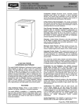
DIRECT-VENT DOWNFLOW
CONDENSING GAS FURNACE
for MANUFACTURED HOUSING
Utilizing the extensive resources available to Bryant, a new
standard of excellence has been achieved with the model
351DAS Downflow Furnace for manufactured (mobile) or
modular homes.
The model 351DAS is a unique downflow condensing furnace with features like no other product in its class. The
351DAS builds on the many Bryant successes in the furnace
industry and establishes a new standard for high-efficiency
gas furnaces.
FEATURES
Factory Configuration—Factory configured for downflow applications in manufactured (mobile) or modular homes.
The model 351DAS is available in 3 heat/airflow combinations.
Sealed Combustion (Direct-Vent) System—Enclosed burner
assembly isolates operating noise without the expense of
sound deadening devices. The sealed combustion (directvent) system brings outdoor air directly into the combustion
chamber, reducing infiltration of cold air into the structure and
reducing heat loss.
3-Pass Primary Heat Exchangers—This design accelerates
heat transfer and extracts heat that conventional heat exchangers waste up the flue. The weld-free primary heat exchangers are made of aluminized steel for corrosion
resistance.
351DAS
Size 080
Series A
Flow-Through Secondary Heat Exchangers—Each cell is laminated with our patented EverlasticTM polypropylene for greater
resistance to corrosion. This breakthrough in heating technology
helps extend the life of the furnace for years of trouble-free performance.
Warranty—Limited 20-year Warranty on the heat exchangers
for the original owner in single family residence. Contact your
dealer for details. Two-year limited parts and labor warranty on
entire unit.
Monoport Inshot Burners—Produce precise air-to-gas mixture
which gives a clean burn. The large monoport on the inshot or
injection-type burners seldom, if ever, needs cleaning.
Control Center—The printed-circuit board and all internal wiring
are factory installed. Convenient terminals permit quick-connection of a thermostat, a humidifier, an air cleaner, and air conditioning control circuits.
As an added feature, the control has a built-in status indicator
and self-test feature. The status indicator flashes to indicate a
problem condition and assists the servicer in diagnosis. The selftest feature allows for a complete check of the major components in only seconds.
Combustion Air and Ventilation—The 351DAS advanced design
allows Schedule 40PVC, PVC-DWV, SDR-21 PVC, SDR-26
PVC (not approved in Canada), ABS-DWV, or ABS-F628
Schedule 40 pipe to bring outdoor air into the furnace for combustion. The extracted heat lowers the temperature of the combustion products to a point (typically below 115°F) that any of the
approved types of pipe can also be used for venting combustion
products outside the structure. The combustion-air and vent
pipes can terminate through a side wall or through the roof when
using 1 of our approved vent termination kits.
Fully-Insulated Casing—Foil-faced insulation in the heat exchanger section cuts heat loss, and insulation in the blower section reduces noise levels. The casing also has the required
openings for left- or right-side connection of gas, electric, drain,
and vent connections.
Certifications—The 351DAS units are A.G.A. and C.G.A. design
certified for use with natural and propane gases, as well as
GAMA efficiency rating certified. The furnace is factory-shipped
for use with natural and propane gases. (All parts necessary to
convert the gas valve for propane gas use are shipped with the
furnace.) Model 351DAS is design certified for installation in
manufactured (mobile) homes.
Quality Registration—The 351DAS is engineered and manufactured under an ISO 9001 registered quality system.
Form No. PDS 351D.80.1
—2—
39 7⁄8"
⁄16"
5⁄8"
13⁄16"
11
26 15⁄16"
28 1⁄2"
26 1⁄4"
22 5⁄16"
19"
OUTLET
2-IN.
COMBUSTIONAIR CONN
DIA
GAS CONN
1⁄2-IN.
7
⁄8-IN. DIA
POWER CONN
1⁄2-IN. DIA
THERMOSTAT ENTRY
2-IN. VENT CONN
22 11⁄16"
INLET
24 3⁄16"
18 1⁄4"
13/16"
A
AIRFLOW
D
OUTLET
INLET
E
13/16"
11/16"
OUTLET FLANGE
AS SHIPPED
(REMOVE IN FIELD)
30 13⁄16"
32 5⁄8"
TYP
33 1⁄4"
TYP
A
17-1/2
17-1/2
21
UNIT SIZE
036080
048080
060080
19-3/8
15-7/8
15-7/8
D
DIMENSIONS (In.)
E
19-1/2
16
16
DIA
POWER CONN
SHIP. WEIGHT (Lb)
197
175
172
7⁄8-IN.
7⁄8-IN. DIA
ACCESSORY
POWER ENTRY
CONDENSATE DRAIN
TRAP LOCATION
24 1⁄2"
27 9⁄16"
TYP
27 5⁄8"
29 11⁄16"
TYP
NOTES: Minimum return-air opening at furnace, based on metal
duct. If flex duct is used, see flex duct manufacturer's
recommendation for equivalent diameters:
1. For 800 CFM 16-in. round or 14- 1/2 X 12-in. rectangle.
2. For 1200 CFM 20-in. round or 14- 1/2 X 19-1/2 in. rectangle.
3. For 1600 CFM 22-in. round or 14- 1/2 X 23-1/4 in. rectangle.
CONDENSATE DRAIN
TRAP LOCATION
OR ALTERNATE
1
⁄2-IN. DIA GAS CONN
30
1⁄2"
11/16"
22 11⁄16"
26 15⁄16"
26 1⁄4"
A98647
24 1⁄2"
2-IN.
COMBUSTION
-AIR CONN
22 5⁄16"
1
⁄2-IN. DIA
GAS CONN
2-IN. VENT CONN
DIA
THERMOSTAT ENTRY
1⁄2-IN.
INSTALLATION
This forced air furnace is equipped for use with natural or propane gas at altitudes 0 - 10,000 ft (0 - 3,050m).
This furnace is for indoor installation in a manufactured (mobile) or modular home.
This furnace may be installed on combustible flooring in alcove or closet at minimum clearance from combustible material.
This appliance requires a special venting system. Refer to the installation instructions for parts list and method of installation. This furnace is for use with schedule-40 PVC,
PVC-DWV, or ABS-DWV pipe, and must not be vented in common with other gas-fired appliances. Construction through which vent/air intake pipes may be installed is
maximum 24 inches (600 mm), minimum 3/4 inches (19 mm) thickness (including roofing materials).
Furnace must be installed level, or pitched forward within 1/2 inch of level for proper drainage. Failure will result
in equipment or property damage.
LEVEL (0")
TO
1/2" MAX
FRONT
DOWNFLOW
This furnace is approved for
DOWNFLOW installation.
1"
TOP/PLENUM
MINIMUM INCHES CLEARANCE TO
COMBUSTIBLE CONSTRUCTION
DOWNFLOW POSITION:
*
†
Mimimum front clearance for service 30 inches (762mm).
0"
For installation on combustible floors only when installed on special base No. KGASB0201ALL,
Coil Assembly, Part No. CD5 or CK5, or Coil Casing, Part No. KCAKC.
BA
C
SI
K
FU
MANUFACTURED MOBILE HOME STANDARDS
This furnace must be installed with a direct vent (combustion air and flue) system, and use a factory
accessory termination kit.
Condensate Trap
on LEFT Side
FR
ON
T
SE
D
SI
E
0"
FR
ON
RV
IC
E
T
0"
*
30
MIN
3"
BOTTOM
This furnace must be installed in accordance with the manufacturer's instructions and Manufactured
Home Construction and Safety Standard, Title 24 CFR, Part 3280 or, when such standard is not
applicable, the ANSI A225.1, Standard for Manufactured Home Installation (Manufactured Home Sites,
Communities and Set-Ups), or the Mobile Homes Standard CAN/CSA-Z240 MH Series-M86.
RN
DE
E
AC
Clearance in inches
0"
†
Condensate Trap
on RIGHT Side
TUBE ROUTING
BURNER ENCLOSURE
PRESSURE
REFERENCE TUBE
ASSEMBLY
CAP / PLUG
CAP / PLUG
LOWER COLLECTOR BOX
PRESSURE TUBE
LOWER COLLECTOR
BOX PRESSURE TUBE
UPPER COLLECTOR
BOX PRESSURE TUBE
UPPER COLLECTOR BOX
PRESSURE TUBE
COLLECTOR BOX
DRAIN TUBE
GAS VALVE
GAS VALVE
COLLECTOR BOX
DRAIN TUBE
CONDENSATE TRAP
COLLECTOR BOX EXTENSION DRAIN
TUBE
DRAIN TUBES ROUTED IN
FRONT OF GAS VALVE
INDUCER HOUSING
DRAIN TUBE
INDUCER HOUSING
DRAIN TUBE
DRAIN TUBE
COUPLING
BURNER ENCLOSURE
PRESSURE REFERENCE
TUBE ASSEMBLY
CONDENSATE TRAP
NOTE: 1. All tubing must be connected securely and routed to avoid kinks and traps.
324997-201 REV. A / LIT
A99001e
CONTROLS—THERMOSTATS AND ZONING
THERMOSTAT—NON-PROGRAMMABLE
THERMOSTAT—PROGRAMMABLE
For Use with 1-Speed Air Conditioner—TSTATBBNAC01-B
For Use with 2-Speed Air Conditioner—TSTATBBN2S01-B
For Use with 2-Speed Heat Pump—TSTATBBN2S01-B
For Use with 1-Speed Air Conditioner—TSTATBBPAC01-B
For Use with 2-Speed Air Conditioner—TSTATBBP2S01-B
For Use with 1-Speed Heat Pump—TSTATBBPDF01-B
For Use with 2-Speed Heat Pump—TSTATBBP2S01-B or TSTATBBPDF01-B
THERMIDISTAT—PROGRAMMABLE THERMOSTAT
—with Humidity Control
TSTATBBPRH01-B
—3—
SPECIFICATIONS
UNIT SIZE
036080
048080
060080
80,000
75,000
80,000
75,000
80,000
75,000
90.0
40—70
0.15
0.50
1190
1245
90.0
30—60
0.15
0.50
1285
1525
90.0
20—50
0.15
0.50
1785
1925
7.6
10.4
14
36
115—60—1
104—127
10.0
13.4
14
28
14.1
18.4
12
31
RATINGS AND PERFORMANCE
Input Btuh*
Output Capacity† ICS
AFUE%†
Nonweatherized ICS
Certified Temperature Rise Range °F
Certified External Static Pressure
Downflow
Downflow
Heating
Cooling
Heating
Cooling
Airflow CFM‡
ELECTRICAL
Unit Volts—Hertz—Phase
Operating Voltage Range Min—Max**
Maximum Unit Amps
Unit Ampacity††
Minimum Wire Size
Maximum Wire Length (Ft)‡‡
Maximum Fuse Size or Ckt Bkr Amps
(Time-Delay Fuse Recommended)
Transformer (24v)
External Control
Power Available
Air Conditioning Blower Relay
15
15
40va
12va
21va
Standard
Heating
Cooling
20
CONTROLS
Limit Control
Heating Blower Control (Off Delay)
Burners (Monoport)
Gas Connection Size
4
SPST
Factory Set at 135 Sec
4
1/2-in. NPT
4
GAS CONTROLS
Gas Valve (Redundant/Gas Convertible)
Manufacturer
White-Rodgers
Min Inlet Pressure (In. wc)
4.5 (Natural Gas) 11.0 (Propane)
Max Inlet Pressure (In. wc)
13.6 (Natural and Propane Gases)
Hot Surface
Ignition Device
BLOWER DATA
Direct-Drive Motor HP (Permanent Split Capacitor)
Motor Full Load Amps
RPM (Nominal)—Speeds
Blower Wheel Diameter x Width (In.)
Filter Size (In.)—Permanent Washable
1/3
5.8
1/2
7.9
1075—4
11 x 8
10 x 7
(1) 16 x 25 x 1
3/4
11.1
11 x 10
(1) 20 x 25 x 1
FACTORY-AUTHORIZED AND LISTED, DEALER-INSTALLED OPTIONS
Downflow Base***
KGASB0201ALL
2-in.—KGAVT0101BRA
3-in.—KGAVT0201BRA
2-in.—KGAVT0501CVT
3-in.—KGAVT0601CVT
Vent Termination Kit (Bracket Only for 2 Pipes)
Concentric Vent Termination Kit (Single Exit)
Condensate Freeze Protection Kit
KGAHT0101CFP
Electronic/Mechanical Air Cleaner
Model AIRA or 902B or MACA
Humidifier
Heat/Energy Recovery Ventilator
Model HUM
Model VA3B, VB5B, VC5B, or VL3A
* Gas input ratings are certified for elevations to 2000 ft. For elevations above 2000 ft, reduce ratings 2% for each 1000 ft above sea level. In Canada, derate
the unit 5% from 2000 to 4500 ft above sea level.
† Capacity and AFUE in accordance with U.S. Government DOE test procedures.
‡ Airflow shown is for top only return-air supply.
** Permissible voltage limits for proper furnace operation.
†† Unit ampacity = 125% of largest component’s full load amps plus 100% of all other potential operating components (EAC, humidifier, etc.).
‡‡ Length shown is measured 1 way along wire path between unit and service panel for maximum 2% voltage drop.
*** Required for installation on combustible floors when no coil box is used, or when any coil box other than a Bryant CD5 or CK5 cased coil is used.
ICS—Isolated Combustion System
—4—
COMBUSTION-AIR AND VENT PIPING
MAXIMUM ALLOWABLE PIPE LENGTH (FT)
ALTITUDE
ABOVE SEA
LEVEL (FT)
0 to 2000
2001 to 3000
3001 to 4000
4001 to 5000†
5001 to 6000†
6001 to 7000†
7001 to 8000†
8001 to 9000†
9001 to
10,000†
UNIT SIZE
TERMINATION TYPE
036080
048080
060080
2 Pipe or 2-In. Concentric
036080
048080
060080
036080
048080
060080
036080
048080
060080
036080
048080
060080
036080
048080
060080
036080
048080
060080
036080
048080
060080
036080
048080
060080
PIPE DIA
(IN.)*
1-1/2
2
2-1/2
2
2 Pipe or 2-In. Concentric
2 Pipe or 2-In. Concentric
2 Pipe or 2-in Concentric
2 Pipe or 2-In. Concentric
2 Pipe or 2-In. Concentric
2 Pipe or 2-In. Concentric
2 Pipe or 2-In. Concentric
2 Pipe or 2-In. Concentric
1
10
55
70
49
2
NA
50
70
44
NUMBER OF 90° ELBOWS
3
4
NA
NA
35
30
70
70
30
25
5
NA
30
70
25
6
NA
20
70
15
2-1/2
70
70
70
70
70
70
2
46
41
28
23
22
13
2-/12
70
70
70
70
70
70
2
44
39
26
21
20
11
70
2-1/2
70
70
70
70
70
2
41
36
23
18
17
8
2-1/2
70
70
70
70
70
70
2
38
33
21
16
15
6
2-1/2
70
70
68
67
66
64
NA
2
36
31
19
14
12
2-1/2
66
65
63
62
60
59
2
33
28
17
12
10
NA
2-1/2
62
60
58
56
55
53
2
30
25
14
9
7
NA
2-1/2
57
55
53
51
49
47
* Disk usage—Unless otherwise specified, use perforated disk assembly (factory-supplied in loose parts bag).
† Vent sizing for Canadian installations over 4500 ft (1370m) above sea level are subject to acceptance by the local authorities having jurisdiction.
NA—Not Allowed; pressure switch will not make.
NOTES:
1. Do not use pipe size greater than those specified in table or incomplete combustion, flame disturbance, or flame sense lockout may occur.
2. Size both the combustion-air and vent pipe independently, then use the larger diameter for both pipes.
3. Assume two 45° elbows equal one 90° elbow. Long radius elbows are desirable and may be required in some cases.
4. Elbows and pipe sections within the furnace casing and at the vent termination should not be included in vent length or elbow count.
5. The minimum pipe length is 5 ft for all applications.
MAXIMUM ALLOWABLE EXPOSED VENT PIPE LENGTH (FT) WITH AND WITHOUT INSULATION
IN WINTER DESIGN TEMPERATURE AMBIENT*
UNIT SIZE
036080
048080
060080
WINTER DESIGN
TEMPERATURE
(°F)
MAX PIPE
DIAMETER
(IN.)
WITHOUT
INSULATION
WITH 3/8-IN. OR
THICKER INSULATION†
20
2-1/2
70
70
0
2-1/2
47
70
–20
2-1/2
28
70
* Pipe length (ft) specified for maximum vent pipe lengths located in unconditioned spaces. Vent pipes located in unconditioned space cannot exceed the
total allowable pipe length as specified in Maximum Allowable Pipe Length table.
† Insulation thickness based on R value of 3.5 per in.
—5—
CONDENSATE TRAP
FURNACE
DOOR
CONDENSATE
TRAP
1⁄4
FURNACE
SIDE
OD
COLLECTOR BOX TO
TRAP RELIEF PORT
11 2
1⁄2
OD
INDUCER HOUSING
DRAIN CONNECTION
34
5⁄8
4 78
OD
COLLECTOR BOX
DRAIN CONNECTION
71 8
SCREW HOLES FOR
DOWNFLOW (OPTIONAL)
13 4
FIELD
DRAIN
CONN
26 1 4
SIDE VIEW
11 2
WIRE TIE
GUIDES
(WHEN USED)
FRONT VIEW
FRONT VIEW
78
21 4
1⁄2-IN.
PVC OR CPVC
SIDE VIEW
(SHOWN ON RIGHT-HAND SIDE. MAY
BE INSTALLED ON LEFT-HAND SIDE.)
A98648
®
ama
CANADIAN GAS ASSOCIATION
MEETS DOE RESIDENTIAL CONSERVATION SERVICES
PROGRAM STANDARDS.
A PP R O VED
R
Before purchasing this appliance, read important
energy cost and efficiency information available
from your retailer.
As an ENERGY STARSM Partner, Bryant Heating & Cooling
Systems has determined that this product meets the
ENERGY STAR guidelines for energy efficiency.
REGISTERED QUALITY SYSTEM
—6—
These products are engineered and manufactured under an
ISO 9001 registered quality system.
ACCESSORIES
CONCENTRIC VENT
B IN. DIA PVC
VENT/EXHAUST
F
E
C IN. DIA
13/16
11/2
D
A
B IN. DIA PVC
INTAKE/COMBUSTION AIR
A97110
DIMENSIONS (In.)
PART NO.
A*
B
C
D†
E
F
KGAVT0501CVT
33-3/8
2
3-1/2
16-5/8
6-1/4
5-3/4
KGAVT0601CVT
38-7/8
3
4-1/2
21-1/8
7-3/8
6-1/2
*Dimension A will change accordingly as dimension D is lengthened or shortened.
†Dimension D may be lengthened to 60 in. maximum. Dimension D may also be shortened by
cutting the pipes provided in the kit to 12 in. minimum.
ACCESSORY DOWNFLOW SUBBASE
LOCATING
TAB
1 1/4″ TYP
PLENUM
OPENING
B
D
1
2
3
A
4
LOCATING
TAB
4
3
2
C
FACTORY-SUPPLIED
FIELD-INSTALLED
INSULATION
1
A88207
A97427
Disassembled
FURNACE
CASING
WIDTH
Assembled
PLENUM OPENING*
FLOOR OPENING
FURNACE IN DOWNFLOW APPLICATION
A
B
C
D
HOLE NO.
FOR WIDTH
ADJUSTMENT
17-1/2
Furnace with or without CD5 or CK5 Coil
Assembly or KCAKC Coil Box
15-1/8
19
16-3/4
20-3/8
3
21
Furnace with or without CD5 or CK5 Coil
Assembly or KCAKC Coil Box
18-5/8
19
20-1/4
20-3/8
2
* The plenum should be constructed 1/4 in. smaller in width and depth than the plenum dimensions shown above.
—7—
AIR DELIVERY—CFM (With Filter)*
EXTERNAL STATIC PRESSURE (In. wc)
RETURN-AIR
SUPPLY
SPEED
0.1
0.2
0.3
0.4
0.5
0.6
0.7
036080
Top
High
Med-High
Med-Low
Low
1535
1395
1200
1040
1470
1350
1175
1020
1405
1300
1125
990
1330
1225
1065
960
1245
1155
1030
910
1160
1080
970
860
1065
985
890
785
935
880
780
680
048080
Top
High
Med-High
Med-Low
Low
1750
1495
1310
1135
1685
1455
1260
1105
1635
1405
1225
1075
1575
1355
1170
1040
1525
1305
1125
995
1445
1250
1095
995
1380
1185
1040
910
1310
1120
980
860
060080
Top
High
Med-High
Med-Low
Low
2200
2100
1815
1560
2175
2025
1760
1555
2085
1945
1720
1515
2025
1865
1670
1460
1925
1785
1620
1435
1820
1700
1550
1390
1735
1620
1480
1340
1635
1540
1405
1270
UNIT SIZE
0.8
* A filter is required for return-air supply.
SERVICE TRAINING
Packaged Service Training programs are an excellent way to increase your
knowledge of the equipment discussed in this manual, including:
• Unit Familiarization
• Maintenance
• Installation Overview
• Operating Sequence
A large selection of product, theory, and skills programs is available, using popular
video-based formats and materials. All include video and/or slides, plus companion
book.
Classroom Service Training plus "hands-on" the products in our labs can mean
increased confidence that really pays dividends in faster troubleshooting, fewer
callbacks. Course descriptions and schedules are in our catalog.
CALL FOR FREE CATALOG 1-800-962-9212
[ ] Packaged Service Training
[ ] Classroom Service Training
A94328
SPECIFICATIONS SUBJECT TO CHANGE WITHOUT NOTICE
UNIT MUST BE INSTALLED IN ACCORDANCE
WITH INSTALLATION INSTRUCTIONS
Cancels: New
© 1999 Bryant Heating & Cooling Systems, 7310 W. Morris St., Indianapolis, IN 46231
—8—
PRINTED IN U.S.A.
Catalog No. 5235-100
1-99