1
Receiver Installation
Transmitter Installation
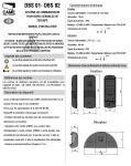
Remove the plastic motor cover, press the aeration grill from the
inside of the cover in order to dislodge it from the place it was
originally mounted, as shown in figure 1.
Open the Receiver board as shown in figure 2
Before proceeding with the installation of the transmitter,
make sure the distance between the two photoelectric cells
are the same as the measurements shown in the following
figures.
30 mm
max
1
150
+/- 30 mm
2
C
NC
24V
0
TS
643#.#
1
2
Use the dip-switches to select which photo diode to use, as
shown in figure 3.
Close the receiver board with the relevant shell and secure with
the screws provided as shown in figure 4.
3
minimum distance between
TX-RX = 30 mm
4
C
NC
24V
0
TS
643#.#
• Secure the base of the transmitter
UNI6954 3.9x32 screws .
1
2
24V
0
TS
C
NC
#.#
1
2
Take the cable already connected to the Receiver and place the
semicircular plate with the Receiver where the aeration grid was
located, hooking it to the automatic system’s case, and then
connect the cable to the terminal board as instructed in column
4. For BZ series automatic systems, cut off the side wings as
shown in figure 5
5
C
NC
24V
0
TS
643#.#
, using the supplied
1
2