1
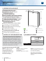
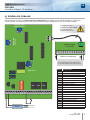
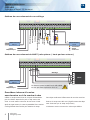
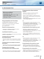
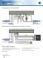
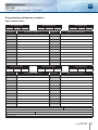
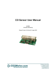
FR
FRANCAIS
EN
ENGLISH
CIP12DR
Interface d’appel 12 boutons
Telephone Entry System - 12 users
Gamme: Contrôle d’Accès Intégré / Range: Integrated Access Control
MANUEL D’INSTALLATION
INSTALLATION MANUAL
Group Products
MANUEL D’INSTALLATION
FR
CIP12DR
Interface d’Appel 12 boutons
1] PRÉSENTATION PRODUIT
Alimentation 18V DC ou 12V AC.
Consommation max 300 mA.
Compatible avec tous les centraux
téléphoniques courants.
12 numéros d’appel de jour.
12 numéros d’appel de nuit.
Occupe seulement 1 ligne interne analogique.
Pour poste directement en fréquences vocales
ou commutable en fréquences vocales.
3 relais 1 NO NF 3A/ 125V AC ou 3A/30V DC.
1 entrée ligne interne analogique.
1 entrée/sortie HP-Micro extérieur (MHPT).
Potentiomètre de volume pour l’écoute.
Programmation de l’interface
par poste téléphonique.
Temps de communication : 45s par défaut.
1 code maître sur 4 termes programmable.
numéros d’appels sur 15 chiffres maximum.
1 bouton poussoir intérieur pour déverrouillage
de la porte (entre B1 et M).
1 contact extérieur Jour/Nuit.
1 relais d’ouverture de porte NO / NF
(commandé par BP intérieur ou téléphonie).
1 relais de déclenchement caméra NO / NF
couplé au temps de conversation.
1 relais NO / NF (commandé par téléphonie).
2] RAPPELS ET RECOMMANDATIONS
Ce produit est livré avec des varistances.
Celles-ci doivent être montées directement sur les
bornes de la gâche (ventouse, moteur,…) commandée par l’équipement. Si l’appareil fonctionne
avec plusieurs gâches, chacune doit être équipée
de varistance. La varistance limite les surtensions
provoquées par le bobinage de la gâche – effet de
self. Dans le cas où la ventouse utilisée est du type
“Shear Lock”, celle-ci doit être alimentée par une
alimentation indépendante du CIP 12DR.
Certification CE
DEEE
Certification R&TTE
IP43
-20°C à +55°C
3] ÉLEMENTS FOURNIS
Varistance
CIP 12DR
2
Au sujet des borniers du CIP 12DR
Relais 1 : Relais d’ouverture
porte. Ce relais peut être
commandé par l’appui sur
le bouton poussoir B1 ou par
la téléphonie (ouverture par
appui sur la touche 1
du combiné de l’appelé).
2
cdvi.com
cdvigroup.com
Relais 2 : Relais commandé
pendant le temps de
conversation.
Peut être couplé à une caméra.
Relais 3 : Commandé par la téléphonie (par appui sur la touche 2
du combiné de l’appelé).
Pour régler l’écoute du haut
parleur, tourner la résistance
ajustable marquée “Ecoute HP
extérieur”.
MANUEL D’INSTALLATION
FR
CIP12DR
Interface d’Appel 12 boutons
4] SCHÉMA DE CÂBLAGE
Raccordement conseillé sur lignes internes analogiques d’un PABX. Le CIP 12DR travaille en fréquences
vocales (DTMF) et comprend une carte principale et un module d’adaptation pour les boutons d’appel.
Réglage usine.
Ne pas toucher.
+
La distance entre
le MHPT et le CIP 12DR
ne doit pas être
supérieure à 10 m.
2
C
+
S
Écoute HP
Extérieur
-
C
S
Module d’appel
12 boutons
1
2
3
4
5
6
7
8
9 10 11 12 C
Bouton 1 à bouton 12
+
Il est recommandé de positionner
le module d’appel près des boutons
-
Relais ligne
Gain micro
12 V L1 L2 1 M+ M- 2
Alimentation
12 V ~
RL1
RL2
RL3
B M B2 B3 R1 C1 T1 R2 C2 T2 R3 C3 T3
230 V
Bornier
Correspondance
12
Alimentation 12V AC ou 18V DC
V
Alimentation 12V AC ou 18V DC
L1
Ligne téléphonique analogique
L2
Ligne téléphonique analogique
1
HP MHPT extérieur
M+
Alimentation MPHT 12V
M-
Alimentation MHPT 0V
2
Micro MHPT extérieur
B1
Bouton poussoir intérieur porte 1
M
Commun boutons poussoirs
B2
Contact Jour/Nuit
B3
Strap de remise à zéro
R1
Contact repos relais 1
C1
Contact commun relais 1
T1
Contact travail relais 1
R2
Contact repos relais 2
C2
Contact commun relais 2
T2
Contact travail relais 2
R3
Contact repos relais 3
C3
Contact commun relais 3
T3
Contact travail relais 3
cdvi.com
cdvigroup.com
3
MANUEL D’INSTALLATION
FR
CIP12DR
Interface d’Appel 12 boutons
Schéma de raccordement du verrouillage
Ligne
téléphonique
Contact
jour/nuit
Commun
Micro extérieur
BP intérieur
Alimentation
12 V ~
Sortie 12 V
230 V
HP extérieur
12 V L1 L2 1 M+ M- 2 B1 M B2 B3 R1 C1 T1 R2 C2 T2 R3 C3 T3
V1
V1
+
-
Alimentation
12 V
230 V
Varistance
Gâche
Ventouse
Schéma de raccordement du MHPT (microphone / haut-parleur externe)
12 V L1 L2 1 M+ M- 2 B1 M B2 B3 R1 C1 T1 R2 C2 T2 R3 C3 T3
Blindage
6
1
2
B
-
230 V Alimentation
12 V ~
Ligne
téléphonique
MPHT
+
La distance entre le MHPT et le CIP 12DR
ne doit pas être supérieure à 10 m.
Procédure interne à la mise
sous tension ou à la remise à zéro
Câblez un strap entre B3 et M. Coupez l’alimentation
puis la rétablir. Attendre 5s puis un bip sonore est
émis. Le code maître usine est de nouveau ***#.
Après le signal sonore, il existe la possibilité d’une remise
à zéro générale des numéros par maintien du strap.
4
cdvi.com
cdvigroup.com
Deux bips confirment l’effacement de tous les numéros.
Enlevez le strap entre B3 et M (régulièrement des bips
sont émis tant que le strap est présent)
L’utilisateur retrouve toutes les valeurs par défaut.
MANUEL D’INSTALLATION
FR
CIP12DR
Interface d’Appel 12 boutons
5] PROGRAMMATION
Valeurs par défaut
-
Temporisation porte : 1s
Temporisation conversation/caméra : 45s
Aucun numéro d’appel
Mode jour/nuit par contact extérieur
Code maître : ***#
Programmation des numéros
de jour
- Appuyez sur *3 suivi du numéro du bouton
qui servira à l’appel (bouton 01 à 12)
- Entrez le numéro d’appel (15 chiffres max) puis
après le dernier chiffre, attendez 3s le bip sonore
de confirmation.
- Si trois bips sont émis, cela signifie que le numéro
entré est déjà programmé.
Programmation de l’interface
OU
La programmation s’effectue par un poste
téléphonique en communication avec l’interface.
Chaque programmation est validée
par un signal sonore.
- Après avoir tapé le numéro du bouton (01 à 12),
il est possible que trois bips soient émis.
Cela signifie que le bouton possède déjà un numéro.
- Effacer le numéro par ** ou recommencer
une programmation par *3 ou autre
Entrée en programmation :
Programmation des numéros de nuit
- Décrochez un combiné et composez le numéro
de la ligne où est raccordé le CIP
- Appuyez sur *4 suivi du numéro du bouton
qui servira à l’appel (bouton 01 à 12)
- Si trois bips sont émis, cela signifie que le numéro
entré est déjà programmé.
puis attendre deux sonneries.
Un bip confirme l’entrée en communication.
Composez le code maître. Deux bips sonores confirme
l’entrée en programmation.
Programmation du temps
de communication
- Appuyez sur *0 suivi de la temporisation souhaitée
(de 001 à 120 sec). Un bip confirme la programmation.
Programmation du temps d’ouverture
de la porte
- Appuyez sur *1 suivi de la temporisation souhaitée
(de 01 à 99s). Un bip confirme la programmation.
- Entrez le numéro d’appel (15 chiffres max) puis
après le dernier chiffre, attendez 3s le bip sonore
de confirmation.
OU
- Après avoir tapé le numéro du bouton (01 à 12),
il est possible que trois bips soient émis.
Cela signifie que le bouton possède déjà un numéro.
- Effacer le numéro par ** ou recommencer
une programmation par *4 ou autre
Programmation du mode Jour/nuit
- Appuyez sur *5 suivi de 0 pour fonctionner
avec le contact extérieur ou 1 pour fonctionner
par téléphone. Un bip confirme la programmation.
Programmation du temps
de commutation du troisième relais
Programmation du code maître
- Appuyez sur *2 suivi de la temporisation souhaitée
(de 01 à 99s). Un bip confirme la programmation.
- Appuyez sur *6 suivi des 4 termes du nouveau code
maître. Un bip confirme la programmation.
Le code maître ne peut pas contenir la touche #.
cdvi.com
cdvigroup.com
5
MANUEL D’INSTALLATION
FR
CIP12DR
Interface d’Appel 12 boutons
Sortie de la programmation :
- Après le bip sonore de confirmation
d’une programmation, un délai sans action de 15s
provoque la sortie de la programmation en émettant
deux bips.
- Il est aussi possible de sortir de programmation
à n’importe quel moment en appuyant
sur la touche # du téléphone.
La communication est automatiquement coupée.
Raccrochez.
En cas d’erreur de manipulation, trois bips sonores
sont émis. Recommencez la manipulation.
Utilisation de l’interface
L’appel se fait par l’intermédiaire d’un des 12 boutons
d’appel.
Sur le poste téléphonique appelé, les actions possibles
sont les suivantes :
• Appuyez sur “0” pour couper
sans commande de relais
• Appuyez sur “1” pour fermer
• Appuyez sur “2” pour fermer
• Appuyez sur “3” pour fermer
et couper la communication
• Appuyez sur “4” pour fermer
et couper la communication
la communication
le relais 1
le relais 3
le relais 1
le relais 3
Ne pas raccrocher le combiné sans avoir appuyé sur
un des chiffres ci-dessus, sous peine d’attendre la fin
du temps de conversation avant tout nouvel appel.
Utilisation du mode jour/nuit
par contact extérieur
- Contact ouvert : appel numéro de jour
- Contact fermé : appel numéro de nuit
Utilisation du mode jour/nuit
par téléphone
(Ne pas oublier de programmer le mode Jour/Nuit
par *5)
- Pour passer du mode jour au mode nuit
et inversement, décrochez un combiné et composez
le numéro de la ligne où est raccordé l’interface.
6
cdvi.com
cdvigroup.com
- Attendre 2 sonneries – un bip est émis
pour confirmer la communication
- Entrez #0 pour passer en mode nuit
- Entrez #1 pour passer en mode jour
Deux bips confirment le changement de mode.
La communication est ensuite coupée.
Trois bips sont émis si le changement de mode est autorisée par le contact extérieur alors que vous tentez
de le modifier par le téléphone. Reprogrammez par *5
Remarque sur le central
téléphonique
Il est conseillé de raccorder le CIP
sur une ligne analogique interne d’un PABX.
Mais, il est cependant possible de travailler
avec une ligne PTT analogique externe.
Si un 0 est programmé comme premier chiffre,
l’interface attend un moment pour permettre
la sélection d’une ligne extérieure avant de composer
les autres chiffres.
Le central téléphonique reste le composant principal
dans cette configuration et détermine dans une large
mesure les possibilités et la convivialité du système.
Il n’y a pas de distinction de tonalité entre un appel
à partir du portier et celui à partir d’une autre ligne
interne, pour le central les deux sont considérés
comme des postes intérieurs équivalents
(à moins que le central n’offre d’autres possibilités
de programmation).
Afin d’éviter lors d’un appel entrant à partir de la ligne
extérieure que l’interface et le portier soient activés,
il y a lieu de programmer le central de manière telle,
que la ligne interne sur laquelle l’interface est connectée ne réagisse pas à l’appel de ligne extérieure.
Si lors d’un appel depuis le portier tous les postes
intérieurs ou plusieurs d’entre eux doivent être interpellés à la fois, le central doit disposer d’une fonction
d’appel général ou d’appel groupé.
Egalement le traitement d’un 2nd appel, lorsqu’un
poste est déjà occupé (indication sonore/visuelle,
mise en attente etc.), est déterminé par le centrale
téléphonique.
MANUEL D’INSTALLATION
FR
CIP12DR
Interface d’Appel 12 boutons
Programmation des numéros d’appels
Tableau d’affectation des numéros d’appel
Temporisation porte 1
Temporisation relais 3
*1
Temporisation conversation
*2
N° du bouton
Numéros d’appel de jour *3
*0
N° du bouton
01
01
02
02
03
03
04
04
05
05
06
06
07
07
08
08
09
09
10
10
11
11
12
12
Temporisation porte 1
Temporisation relais 3
*1
N° du bouton
Numéros d’appel de nuit *4
Temporisation conversation
*2
Numéros d’appel de jour *3
*0
N° du bouton
01
01
02
02
03
03
04
04
05
05
06
06
07
07
08
08
09
09
10
10
11
11
12
12
Programmation effectuée par :
Numéros d’appel de nuit *4
Date :
Immeuble :
N° :
Rue :
Ville :
Autres renseignements :
cdvi.com
cdvigroup.com
7
INSTALLATION MANUAL
EN
CIP12DR
Telephone Entry System - 12 users
1] PRODUCT PRESENTATION
Power supply 18V dc or 12V ac.
Consumption 300mA.
Compatible with most telephone systems.
Up to 12 telephone numbers in day time mode.
Up to 12 telephone numbers
in night time mode.
Requires only one telephone line.
Tone mode operating.
3 relay outputs N/O and N/C 3A/ 125V ac
or 3A/30V dc.
1 analogue telephone line input.
1 input/output external Microphone speaker
(MHPT).
Potentiometer adjustable volume
for the microphone and speaker.
Programming from a telephone handset.
Communication default time: 45 second.
4-digit master code for programming.
15-digit telephone number.
1 Request-to-Exit input (B1 and M).
1 Day/Night contact (open: day, closed: night).
1 door relay N/O and N/C
(activated from push button or telephone).
1 relay output N/O & N/C contact to activate
a camera during conversation.
1 relay output N/O & N/C
(activated from telephone unit).
2] REMINDERS
CE Certification
WEEE
Certification R&TTE
IP43
-20°C to +55°C
3] MOUNTING KIT
AND RECOMMENDATIONS
This device is supplied with varistors.
The varistors must be connected to the strike
terminal (electromagnet…) operated by the device.
If this product works with many strikes, each of
them should have a varistor. The varistor controls
the overload produced by the strike coil – back emf.
If you are using a “Shear Lock” electromagnetic
lock, it is recommended to use a separate power
supply to the one connected to the CIP 12DR.
Varistor
CIP 12DR
2
About the relays of the terminal blocks
Relay 1: Door Relay. The door
relay can be activated from B1
push button or from the telephone
unit (Press 1).
8
cdvi.com
cdvigroup.com
Relay 2: Relay activated during
the conversation time
- can be connected to a camera.
Relay 3: Activated from
the telephone unit (Press 2).
If you experience Feedback, it may
be necessary to adjust the Speaker
and Microphone.
INSTALLATION MANUAL
EN
CIP12DR
Telephone Entry System - 12 users
4] WIRING DIAGRAM
Compatible with analogue telephone lines and PABX. The CIP 12DR works in tone mode (DTMF)
and comprises of the Interface Unit and the Call Button Module, which should be situated in the Door Station.
FACTORY
DO NOT USE!
+
The distance between the
MHPT microphone speaker
and the CIP 12DR should
not exceed 10 m.
+
C
2
S
-
External Panel Volume.
C/W decrease volume.
-
C
S
12-button
calling module
1
2
3
4
5
6
7
8
9 10 11 12 C
Button 1 to button 12
It is recommended to place the
12 button interface module close to
the door station (preferably within).
+
-
Relay Tel.
Internal Volume.
C/W decrease
volume.
12 V L1 L2 1 M+ M- 2
Input voltage
12V ~
RL1
RL2
RL3
B M B2 B3 R1 C1 T1 R2 C2 T2 R3 C3 T3
230 V
Block
Description
12
Input voltage 12V AC or 18V DC
V
Input voltage12V AC or 18V DC
L1
Telephone line analogue
L2
Telephone line analogue
1
MHPT external speaker
M+
MPHT 12V input voltage
M-
MPHT 0V input voltage
2
MHPT external microphone
B1
Push button
M
Common
B2
Day/Night contact
B3
Reset
R1
N/C contact relay 1
C1
Common relay 1
T1
N/O contact relay 1
R2
N/C contact relay 2
C2
Common relay 2
T2
N/O contact relay 2
R3
N/C contact relay 3
C3
Common relay 3
T3
N/O contact relay 3
cdvi.com
cdvigroup.com
9
INSTALLATION MANUAL
EN
CIP12DR
Telephone Entry System - 12 users
Wiring diagram of the locking device
12V out
Contact
Day/Night
Input voltage
12V ~
Microphone
Push button
230V
Common
Speaker
12 V L1 L2 1 M+ M- 2 B1 M B2 B3 R1 C1 T1 R2 C2 T2 R3 C3 T3
V1
V1
+
-
Input voltage
12V
Telephone line
230V
Varistor
Electric strike
Electromagnetic lock
Wiring diagram of the MHPT (external microphone / speaker)
12 V L1 L2 1 M+ M- 2 B1 M B2 B3 R1 C1 T1 R2 C2 T2 R3 C3 T3
Shield
6
1
2
B
-
230V Input voltage
12V ~
Telephone line
MPHT
+
The distance between the MHPT
microphone speaker and the CIP 12DR
should not exceed 10 m.
Factory Reset Procedure
To reset the telephone numbers in the unit,
short terminals B3 & M. Remove the power and then
restore the power again.
Wait 5 seconds.
10
cdvi.com
cdvigroup.com
Two audible beeps confirm that the unit has been
reset to the default values.
Remove the strap between B3 and M.
INSTALLATION MANUAL
EN
CIP12DR
Telephone Entry System - 12 users
5] PROGRAMMING
Release Time for Relay #3
Default Values
-
Door release time: 1 sec
Time conversation/camera: 45 sec
No telephone numbers programmed
Day/Night mode
from interface input contact (automatic)
- master code ***#
Programming
The unit is programmed from a telephone handset.
Dial the extension number or the telephone number
to which the CIP/12DR is connected to.
Each programming change is validated
by an audible beep.
Programming Mode:
- Call the CIP/3DR from a telephone handset.
The unit will answer by emitting an audible beep.
- Enter the master code “***#”,
Two beeps confirm entry in programming mode.
- Press *2 followed by the release time
(from 01 to 99 sec).
A Beep confirms the time for relay #2.
Programming Day time
telephone number
- Press *3 then enter the call button number
(button from 01 to 12)
- If three beeps are emitted the telephone number
is already programmed.
- Enter the telephone number (15-digit maximum)
then after the last digit, wait 3 seconds for the beep
confirmation.
OR
- After entering the call button number (01 to 12),
if three beeps are emitted the telephone number
is already programmed.
- To delete the number press the * twice or press *3
to program another telephone number or enter in
another menu.
Programming Night time
telephone number
- Press *0 followed by the time delay you wish
the unit to disconnect (from 001 to 120 sec).
One audible beep confirms the time set.
- Press *4 then enter the call button number
(button from 01 to 12)
- Enter the telephone number (15-digit maximum)
then after the last digit, wait 3 seconds for the beep
confirmattion.
- If three beeps are emitted the telephone number is
already programmed.
Release Time for Relay #1
OR
- Press *1 followed by the release time
(from 01 to 99 sec).
A Beep confirms the time for relay #1.
- After entering the call button number (01 to 12),
if three beeps are emitted the telephone number
is already programmed.
- To delete the number press the * twice or press *4
to program another telephone number or enter in
another menu.
Communication time
cdvi.com
cdvigroup.com
11
INSTALLATION MANUAL
EN
CIP12DR
Telephone Entry System - 12 users
Programming Day/Night Mode
- Press *5 followed by 0 to activate the mode from
the interface unit contact (automatic switching) or
press 1 to activate the mode from the telephone unit
(manual switching). A beep confirms the new mode.
Exit from programming:
- Once in programming after 15 seconds without any
action, the unit will automatically exit from programming, then two beeps are emitted.
- To exit from programming at any time press the #
from the telephone handset.
The communication will be automatically terminated.
Hang up.
In the case of a programming error, three beeps are
emitted. Restart the programming.
Interface unit
The call is made by pressing one of the call buttons
on the front panel. One beep is emitted to confirm
that the number has been dialed. From the telephone
handset, which receives the call it is possible to:
• Press “0” to end the communication
without activating the relay
• Press “1” to activate relay 1
• Press “2” to activate relay 3
• Press “3” to activate relay 1
and end the communication
• Press “4” to activate relay 3
and end the communication
Activation of the Day/Night mode
from the interface contact (automatic)
- Contact open: Day time mode
- Contact closed: Night time mode
Activation of the Day/Night mode
from the telephone (manual)
- To switch from the day mode to the night mode and
vice versa, dial the number of the interface unit.
- Wait two rings – one beep is emitted to confirm the
communication
- Press #0 to activate the night mode
- Press #1 to activate the day mode
12
cdvi.com
cdvigroup.com
If 0 is programmed as the first digit, the interface
waits a couple of seconds to select an external line
before dialing the other digits.
Remark on the telephone
It is recommended to connect the CIP to an analog
line of the PABX.
Note that the unit can also operate with an external
analog line (standard landline).
If 0 is programmed as the first digit, the interface
waits for a moment to allow the selection of an outside line before dialing the telephone number.
The telephone is the main component in this configuration and determines to a large extent, the potential
and usability of the system.
There is no distinction of tones between receiving a
call from the Entry Audio Panel or internal/external
call. For the PABX both calls are considered equivalent
(unless the PABX offers features that could differentiate between the incoming calls).
In order to avoid an incoming call from the outside
line activating the CIP12DR interface, the PABX must
be programmed to avoid ringing the interface.
If you wish to call from the entry panel all or some telephone extensions then the PABX must programmed
to ring all or some telephone extensions.
The PABX should have a busy line feature that will
indicate that the line is busy (audio / visual feedback).
INSTALLATION MANUAL
EN
CIP12DR
Telephone Entry System - 12 users
Programming telephone numbers
User number table
Door release time 1
*1
Time release relay 3
Conversation time
*2
Button No.
*0
Day time Tel. numbers *3
Button No.
01
01
02
02
03
03
04
04
05
05
06
06
07
07
08
08
09
09
10
10
11
11
12
12
Door release time 1
*1
Button No.
Night time Tel. numbers *4
Time release relay 3
Conversation time
*2
*0
Day time Tel. numbers *3
Button No.
01
01
02
02
03
03
04
04
05
05
06
06
07
07
08
08
09
09
10
10
11
11
12
12
Administrator:
Night time Tel. numbers *4
Date:
Building:
N°:
Street:
City:
Other information:
cdvi.com
cdvigroup.com
13
INSTALLATION MANUAL
CIP12DR
Telephone Entry System - 12 users
NOTES
14
cdvi.com
cdvigroup.com
EN
INSTALLATION MANUAL
EN
CIP12DR
Telephone Entry System - 12 users
cdvi.com
cdvigroup.com
15
Reference : G0301FR0204V02
Extranet : EXE-CDVI_IM CIP12DR CMYK A5 EN-FR 01
CDVI Group
FRANCE (Headquarter/Siège social)
Phone: +33 (0)1 48 91 01 02
Fax: +33 (0)1 48 91 21 21
CDVI
FRANCE + EXPORT
Phone: +33 (0)1 48 91 01 02
Fax: +33 (0)1 48 91 21 21
CDVI
TAIWAN
Phone: +886 (0)42471 2188
Fax: +886 (0)42471 2131
CDVI AMERICAS
[CANADA - USA]
Phone: +1 (450) 682 7945
Fax: +1 (450) 682 9590
CDVI BENELUX
[BELGIUM - NETHERLAND - LUXEMBOURG]
Phone: +32 (0) 56 73 93 00
Fax: +32 (0) 56 73 93 05
Toutes les informations mentionnées à titre indicatif sur le présent document (photos, dessins, caractéristiques
techniques et dimensions) peuvent varier et sont susceptibles de modifications sans notification préalable.
All the information contained within this document (photos, drawing, features, specifications and dimensions)
could be perceptibly different and can be changed without prior notice.
Manufacturing Access Control since 1985
CDVI IBÉRICA
CDVI SWEDEN
[SPAIN - PORTUGAL]
[SWEDEN - DENMARK - NORWAY - FINLAND]
Phone: +34 (0)935 390 966
Fax: +34 (0)935 390 970
Phone: +46 (0)31 760 19 30
Fax: +46 (0)31 748 09 30
CDVI
SUISSE
Phone: +41 (0)21 882 18 41
Fax: +41 (0)21 882 18 42
CDVI
ITALIA
Phone: +39 0331 97 38 08
Fax: +39 0331 97 39 70
CDVI UK
CDVI
CHINA
Phone: +86 (0)10 62414516
Fax: +86 (0)10 62414519
CDVI
MAROC
Phone: +212 (0)5 22 48 09 40
Fax: +212 (0)5 22 48 34 69
DIGIT
FRANCE
Phone: +33 (0)1 41 71 06 85
Fax: +33 (0)1 41 71 06 86
cdvigroup.com
[UNITED KINGDOM - IRELAND]
Phone: +44 (0)1628 531300
Fax: +44 (0)1628 531003