1
CO Sensor User Manual
GR-0001
CM-0205 (USB Devkit)
Manual Version 3.2, Revised 12 August 2015
Summary
This pipeline-type infrared gas detection module uses the principle of infrared absorption (NDIR) to detect the
contents of carbon monoxide in a gas. The module adopts imported high precision infrared detector and
industrial-grade high stability of single chip microcomputer, the product has long life, low cost, high accuracy,
and good long-term stability.
Serial communication baud rate is 9600, the data bits for 8, 1 stop bit, parity checking. Its output interface is:
4 ~ 20 ma output current, 0.4 ~ 2 v, output voltage, RS485 output signal, and TTL level signal.
Application
This sensor can be widely installed for home networks, ventilation systems, industrial controllers, public wall
hangings, pipeline gas detection, environment monitoring etc.
Performance Parameters
1.
2.
3.
4.
5.
6.
7.
8.
9.
10.
11.
12.
13.
14.
15.
16.
17.
18.
19.
20.
21.
22.
23.
Testing environment:atmosphere pressure: 1020 hpa, temperature: 25Ԩ gas flow rate:300ml/min
Detect gas:the content of specific gas in the gas CO
Operation principle:NDIR
Warm-up time:< 2 minutes(20 min the best measurement condition)
Response time:< 5 seconds
T90:15 second (300ml/Min)
Recovery time: 25 seconds
Test flow rate:200--400 mL/Min
Resolution: depends on different test range
Repeatability: ≤ ± 1% FS
Linear error:≤ ± 1% FS
Zero temperature draft: ≤ ± 0.1% FS/Ԩ
Test temperature draft: ≤ ± 0.2% FS/Ԩ
Operating voltage: 12V DC (+/-5 %)
Operating current: max current 50ma, Average current 20 ma
Operating power: < 600 mW
Output signal: 4-20mA current
a. 0.4-2V voltage
b. Modbus RS485 digital
c. Modbus TTL digital
Air intake mouth:M5*3;air outlet mouth:M4*2.5
Operating temperature:-10Ԩ--50Ԩ
Storage temperature:-20Ԩ--60Ԩ
Operating humidity:0%--95%RH (non-condensation)
Operating pressure:1 ± 0.2 个 atmosphere pressure
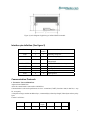
Dimensions:65mm * 35mm * 20mm (L*W*H)
2
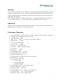
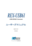
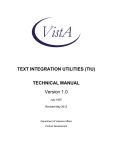
Schematic Diagram
Figure (1) schematic diagram of pipeline type module structure.
Note: the smaller port is the inlet.
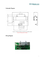
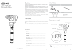
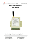
Wiring Diagram
3
Figure (2) wire diagram of pipeline type infrared detection module
Interface pin definition (See figure 2)
Name
VDD
GND
input/outpu
t
I
I
Pin
number
1
3
485 Aor URXD
I/O
5
485 Bor UTXD
VOUT
GND
IOUT
GND
I/O
O
O
O
O
7
6
8
10
12
description
Operating voltage12V
Power and signal ground
485A or module TTL level receiving
end(optional)
485Bor TTL level send end (optional)
Voltage output0.4~2V
Signal ground
Current output 4~20mA
Signal ground
Communication Protocols
1. Format for Universal RS485 bus.
Adpot universal RS485 bus.
All of the control board is connected to a RS485 bus
Communication is universal asynchronous receiver / transmitter (UART), buad rate 9600, 8 data bits, 1 stop
bit, even parity
A complete message contains an address byte, a command byte, a data byte length, N data bytes and two parity
bytes
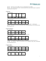
Format is as follows:
start
address
command
4T
1 byte
1 byte
Data
length
1 byte
data
check
over
N bytes
2 byte
4T
4
A. Start/end
Send each message frame need more than 3.5 character time (recommended more than five characters time)
pause interval begins; such as baud rate of 9600, which a character time T 1/9600 * 10 = 1.04ms, therefore
when the system detects that the current byte of the byte interval is greater than about 3.5 T at 3.5ms,
automatically the byte as a message frame's start (proposed sends two messages frame interval above 5ms)
When receiving the first byte (address), each device decodes to determine whether destined for their own.
After the last transmitted character, the same at least more than 3.5 character times (recommend more than five
character times) pause interval to indicate the end of a frame message. A new message can begin after this
pause.
The entire message frame must be continuously sent. If there is more than 3.5 character times pause time before
finish frame two bytes, the receiving device flushes the incomplete message and assumes that the next byte is
the address field of a new message (recommended frames sent between two bytes before the completion of the
message in the same frame two bytes within the interval should be controlled within 1.5 character times).
Likewise, if a new message in front of less than then began receiving device will consider it a continuation of
the previous message in the 3.5 character times. This will result in a communication error, because the value
is definitely wrong when check.
B. Address
Slave address, a byte, range: 1-255 (0xFF). Host will be contacted via the address from the machine into the
address field of the message to the slave strobe. When slave sending response messages, it put his address in
response to the address field in order to let master know which one device to respond. Address 0 is used as a
broadcast address, so that all can be received from the device.
C. Command
That command is function code, a byte, range is 1-255. When the message is sent from the host to the slave,
the function code will let slave to know what specific tasks it need to perform.
For a different command, the slave will make different responses; If done correctly, the nature of the query
command, the machine will return a message with the specified information; the nature of the operating
instruction, the slave will return an empty data (ie, data length byte 0) message to the host to confirm the
success of the operation after the completion of the specified operation, ; If a communication error, the slave
will return an exception response codes, including including abnormal.
Function code specific definition as show in figure 1.
D. Data length
A byte, means the number of bytes of data range of the message frame, if the value is 0 indicates there is no
data
E. Date
Data range including. What you need slave to perform the action or the returned message by the slave adpot.
This information can be a value, the reference address etc. If data range is multi-byte, then the low byte first,
high byte later. For different slave, address and data information are not the same.
5
F Check
Master or slave can use check code to discriminate whether the receiving information is wrong; calibration
method for the 16-bit cyclic redundancy code (CRC16), calibration object includes all bytes of the message
frame (except for the two checksum byte itself).
CRC16 contains two-byte, low byte first, high byte later. CRC16 code calculated by the sending device, placed
in the tail of the sent information. The Equipment to receive information and then recalculate the information
received CRC16 code, comparing the calculated CRC16 code whether matches the received, if they do not
match, then the error.
C language example which calculated by CRC16 code is as following:
//CRC16 code directly calculation method
//*pSendBuf first byte:finger
//nEnd: data check length
unsigned int GetCheck(unsigned char *pSendBuf,unsigned char nEnd)
{
unsigned char i,j;
unsigned int wCrc = (unsigned int)(0xffff);
for(i = 0;i<nEnd;i++)
{
wCrc ^= (unsigned int)(pSendBuf[i]);
for(j = 0;j<8;j++)
{
if(wCrc&0x01)
{
wCrc >>=1;
wCrc ^= 0xA001;
}
else wCrc >>=1;
}
}
return wCrc;
}
6
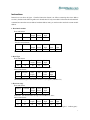
Instructions
Instruction set as shown in figure 1. Detailed instruction format is as follows (assuming these slave address
are 0x01), the data in the following table are in hexadecimal. If only one module on the network and send 0x01
command no return then can use address broadcast address 0x00, you can know how much the current module
address.
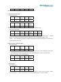
1. Read mode number
Host send format:
Address Command
01
01
Data
length
00
Check
lower
21
Check
high
90
Instruction:The slave which read address is 01
The slave return format:
Address
Command
Data
Data
Data
length
lower
high
01
01
02
71
17
Check
lower
DD
Check
high
A2
Instruction:address is 01 of the slave mode number is 6001(0x1771);
2. Read Type
Host send format:
address Command
01
04
Data
length
00
Check
lower
22
Check
high
C0
Instruction:The measurement type of read address 01 slave;
Slave return format:
Addres Comman
Data
Data
Check
Check
s
d
length
lower
high
01
04
01
16
C0
47
The measurement type of read address 01 slave is (see figure 2, indicates CO)
3. Read test range
Host send format:
Address Command
01
05
Data
length
00
Check
lower
23
Check
high
50
Instruction:the measurement test range of read address 01 slave;
Slave return format:
Addres Comman
Data
Data
Data
Check
Check
s
d
length
lower
high
lower
high
01
05
02
10
27
F5
16
Instruction: (Assume the measurement unit of address 01 slave is 2 as show figure3,indicate ppm),
7
decimal 1,then the test range of address 01 slave is 1000.0ppm(0x2710=10000);
Remarks:This command get data must be combined measurement unit and decimal place two parameter
to get the final test range value;
4. Read unit
Host send format:
Address
Command
01
06
Data
lengt
h
00
Check
lower
Check
high
23
A0
Instruction: the measurement unit of the read address 01 slave;
Slave return format:
address comman
Data
data
Check
Check
d
length
lower
high
01
06
01
02
61
88
Instruction:the measurement unit of address 01 slave is 02 as show figure 3,indicate ppm);
Remarks:This parameter is valid to all concentration value, including test range value, measurement value
and each alarm value;
5. Read decimal place
Host send format:
address Comman
d
01
07
Data
length
00
Check
lower
22
Check
high
30
Instruction: the decimal number of the read address 01 slave data value
Slave return format:
address comman
Data
data
Check
Check
d
length
lower
high
01
07
01
01
70
49
Instruction:the decimal place of address 01 slave is 1, if no decimal place then return value is 0. ;
Remarks:This parameter is valid to all concentration value, including test range value, measurement
value and each alarm value;
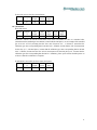
6. Change address
Host send format:
address comman
d
00
10
Data
length
01
data
01
Check
lower
C1
Check
high
B1
Instruction:change all of the slave address on net to 01。
If change successful, (new address is valid), the slave return format:
address Comman
Data
Check
Check
d
length
lower
high
8
01
10
00
2D
C0
Remark: cannot change the new address to broadcast address 00.
7. Read measurement value
Host send format:
Addres comman
Data
s
d
length
01
20
00
Check
lower
39
Check
high
C0
Check
lower
68
Check
high
00
or
address
00
comman
d
20
Data
length
00
Instruction: the concentration measurement value of the read address 01 slave;
The slave return format:
address comman
Data
Data
Data
Check
Check
d
length
lower
high
lower
high
01
20
02
EA
04
FD
63
Instruction: Assure the measurement unit of address 01 slave is 2 ( see figure 3 , means ppm), decimal
place is 1,then the measurement value of the address 01 slave is 125.8ppm(0x04EA=1258);
remark: This command get data must combine measurement unit and decimal place two parameter to
get final measurement value.
8. Restore factory calibration data
Host send format:
address comman Data
d
length
01
31
00
Check
lower
35
Check
high
90
Instruction:restore factory calibration data for address 01 slave, if customer calibrate the zero point
and standard value make wrong, then can use this command to restore factory calibration data.
if change successful, the slave return format:
address Comman
Data
Check
Check
d
length
lower
high
01
31
00
35
90
9. Check ZERO
Host send format:
address comman
d
01
38
Data
length
00
Check
lower
33
Check
high
C0
instruction:correct the current measurement value of read address 01 slave to new zero point(general
use pure nitrogen )
,after correction, please power off first, then power on to observe data .
9
If correction success, the slave return format:
address comman
Data
Check
Check
d
length
lower
high
01
38
00
33
C0
10. Check SPAN
Host send format:
address comman
d
01
39
Data
length
02
Data
lower
64
Data
high
00
Check
lower
9E
Check
high
5C
Instruction: calibrate the current measurement value of the read address 01 slave to a standard value
(determined as the standard gas concentration, related with decimal places). As an example of the standard
gas of 10.01% of CO2 (assuming that the slave unit of measure is%, a decimal, it means that the
calibration gas value corresponding data in decimal 100 = 0X0064; assume that the unit of measurement
for the slave is % , 2 decimal places, it means that the calibration gas value corresponding data in decimal
1001 = 0X03E9; assumes that the slave unit of measurement of% decimal places to 0, it means that the
calibration gas value corresponding data decimal 10 = 0X000A); please power off first and then power on
to observe data after calibration is complete.
If calibration is successful, the slave returns the format:
address comman
Data
Check
Check
d
length
lower
high
01
39
00
32
50
10
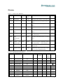
Glossary
Figure 1:function code definition
code
name
Sending
data
Response
data
Function
0x01
0x04
Read model
Read type
0 byte
0 byte
2 byte
1 byte
0x05
Read test range
0 byte
2 byte
0x06
Read unit
0 byte
1 byte
0x07
Read
place
decimal 0 byte
1 byte
Read the model number of selected slave
Read the measurement type of specific Figure 2
slave
Read the measurement range of selected
slave
Read the measurement unit of selected Figure 3
slave
Read the decimal place of the selected
slave
0x10
Chang address
1 byte
0 byte
Modify the communication address of
the selected slave
0x20
Read
measurement
value
0 byte
2 byte
Read the measurement result of selected
slave
0x31
0 byte
0X38
Remove zero 0 byte
adjusted value
Regulate zero
0 byte
0X39
Regulate SPAN
0 byte
remove the specific calibration value of
the selected slave (restore factory set)
regulate the current vale of the selected
slave to zero
calibrate the current value of the selected
slave to given calibration values
2 byte
0 byte
remark
Figure 2:infrared gas type definition
number
01
05
06
07
09
22
23
25
26
27
28
Name
Chemical formula
remarks
Serial
number
Name
Chemic
al
formula
remark
Carbon monoxide
CO
NO2
NO2
NOm
NO
Sulfur dioxide
SO2
ammonia
NH3
Carbon dioxide
CO2
Sulfur hexafuoride
SF6
methane
CH4
hydrocarbon HC(standard gas C3H8)
N2O
N2O
R123a
R123a
11
Figure 3:Unit definition
code
mark
0
PPM
1
PPB
2
PPM
3
‰
4
%
5
%LE
L
6
%VO
L
7
Mg/m3
8
Mg/L
。
。
。
。
。
。
Support
The quickest way to obtain technical support is via email. Please send all support inquires to
[email protected].
Please include a clear, concise definition of the problem and any relevant troubleshooting information or steps
taken so far, so we can duplicate the problem and quickly respond to your inquiry.
Warranty
This sensor comes with a 90 day (warranty period) limited manufacturer’s warranty, starting from the date the
sensor was shipped to the buyer.
During this period of time, CO2Meter.com warrants our products to be free from defects in materials and
workmanship when used for their intended purpose and agrees to fix or replace (at our discretion) any part or
product that fails under normal use. To take advantage of this warranty, the product must be returned to
CO2Meter.com at your expense. If, after examination, we determine the product is defective, we will repair or
replace it at no additional cost to you.
This warranty does not cover any products that have been subjected to misuse, neglect, accident, modifications
or repairs by you or by a third party. No employee or reseller of CO2Meter.com’s products may alter this
warranty verbally or in writing.
Liability
All liabilities under this agreement shall be limited to the actual cost of the product paid to CO2Meter.com. In
no event shall CO2Meter.com be liable for any incidental or consequential damages, lost profits, loss of time,
lost sales or loss or damage to data, injury to person or personal property or any other indirect damages as the
result of use of our products.
Returns
If the product fails under normal use during the warranty period, a RMA (Return Material Authorization)
number must be obtained from CO2Meter.com. After the item is received CO2Meter.com will repair or replace
the item at our discretion.
To obtain a RMA number, call us at or email us at (386) 256-4910 [email protected]. When requesting
a RMA please provide reason for return and original order number.
12
If we determine that the product failed because of improper use (water damage, dropping, tampering, electrical
damage etc.), or if it is beyond the warranty date, we will inform you of the cost to fix or replace the product.
For more information visit our website: www.CO2Meter.com/pages/faq
Contact Us
We are here to help!
For information or technical support, please contact us.
[email protected]
(386) 256-4910 ( Technical Support)
(386) 872-7665 (Sales)
www.co2meter.com
Address:
CO2Meter, Inc.
131 Business Center Drive
Ormond Beach, FL 32174
USA
13