1
10.3
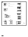
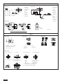
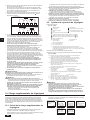
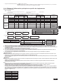
[Fig. 10.3.1]
LOW
A
C
B
G
B
H
C
I
HI
E
D
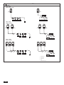
[Fig. 10.3.2]
A: Nitrogen gas
F
J
B: To indoor unit
C: System analyzer
D: Low knob
E: Hi knob
LOW
A
D
E
N
F
B: Low knob
C: Hi knob
D: Valve
O
HI
G: Liquid pipe
E: Liquid pipe
G
C
B
F: Valve
A: System analyzer
N
F: Gas pipe
G: Service port
I
H
H: Gas pipe
H: Three-way joint
I: Outdoor unit
M
K
J: Service port
I: Valve
J: Valve
K: R410A cylinder
J
L: Scale
L
M: Vacuum pump
N: To indoor unit
O: Outdoor unit
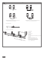
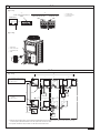
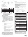
[Fig. 10.3.3]
A
B In case of the R410A cylinder having no syphon pipe.
10.4
[Fig. 10.4.1]
B
[Fig. 10.4.2]
C
A
[Fig. 10.4.3]
B
A
C
E
E
E
D
D
A
B
E
A: Steel wire
B: Piping
D
C: Asphaltic oily mastic or asphalt
D: Heat insulation material A
E: Outer covering B
A: Liquid pipe
B: Gas pipe
C: Electric wire
D: Finishing tape
E: Insulator
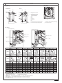
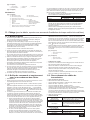
[Fig. 10.4.4]
<A> Inner wall (concealed)
AB
<C> Outer wall (exposed)
<B> Outer wall
D
D
C
<D> Floor (waterproofing)
EB
A B
F
I
<E> Roof pipe shaft
<F> Penetrating portion on fire
limit and boundary wall
I
G
J
D
B
H
F
8
G
B
A: Sleeve
B: Heat insulating material
C: Lagging
D: Caulking material
E: Band
F: Waterproofing layer
G: Sleeve with edge
H: Lagging material
I: Mortar or other incombustible caulking
J: Incombustible heat insulation material
A
1m
1m
A: Syphon pipe