1
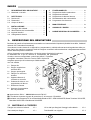
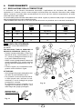
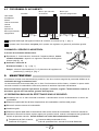
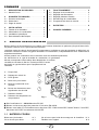
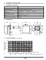
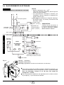
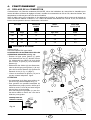
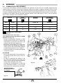
Istruzioni per installazione, uso e manutenzione
Montage und Bedienungsanleitung
Manuel d’entretien
Installation, use and maintenance instructions
I
D
F
GB
Bruciatore di gasolio
Öl-Gebläsebrenner
Brûleur fioul
Light oil burner
Funzionamento monostadio
Einstufiger Betrieb
Fonctionnement à 1 allure
One stage operation
CODICE
CODE
MODELLO - MODELL
MODELE - MODEL
TIPO - TYP
TYPE
3738718
BG4
387 T1
2901862 (13)
Dichiarazione del produttore secondo la normativa 1. BImSchV, 1996
RIELLO S.p.A. dichiara che il seguente prodotto rispetta i valori limite degli NOx imposti dalla
normativa 1. BImSchV, 1996, § 7 (2):
Herstellerbescheinigung gemäß 1. BImSchV, 1996
RIELLO S.p.A. bestätigt, daß folgender Produkt, die von der 1. BImSchV, 1996, § 7 (2)
geforderten NOx - Grenzwerte einhaltet:
Déclaration du producteur selon la directive 1. BImSchV, 1996
RIELLO S.p.A. déclare que le brûleur suivant respect les valeurs limites de NOx imposées par
la directive 1. BImSchV, 1996, § 7 (2):
Producer declaration according to 1. BImSchV, 1996
RIELLO S.p.A. declares, that the following product complies with the NOx limit values indicated
in the 1. BImSchV. 1996 § 7 (2) standard:
Prodotto - Produkt
Produit - Product
Bruciatore di gasolio
Öl-Gebläsebrenner
Brûleur fioul
Light oil burner
Tipo -Typ - Type
Modello - Ausführung
Modèle - Model
392 T1
BG4
RIELLO S.p.A.
1862
INDICE
1.
1.1
DESCRIZIONE DEL BRUCIATORE . . . . . 1
Materiale a corredo . . . . . . . . . . . . . . . . . 1
2.
2.1
2.2
2.3
DATI TECNICI . .
Dati tecnici . . . . .
Dimensioni . . . . .
Campo di lavoro .
3.
3.1
3.2
3.3
3.4
1.
.
.
.
.
.
.
.
.
.
.
.
.
.
.
.
.
.
.
.
.
.
.
.
.
.
.
.
.
.
.
.
.
.
.
.
.
.
.
.
.
.
.
.
.
INSTALLAZIONE . . . . . . . . . . .
Fissaggio alla caldaia. . . . . . . .
Alimentazione del combustibile
Impianti idraulici . . . . . . . . . . . .
Collegamenti elettrici . . . . . . . .
.
.
.
.
.
.
.
.
.
.
.
.
.
.
.
.
.
.
.
.
.
.
.
.
.
.
.
.
.
.
.
.
.
.
.
.
.
.
.
.
.
.
.
.
.
.
.
.
.
.
.
.
.
.
.
.
.
.
.
.
.
.
.
.
.
.
.
.
.
.
.
.
2
2
2
2
3
3
3
4
5
4.
4.1
4.2
4.3
4.4
4.5
FUNZIONAMENTO . . . . . . . . . .
Regolazione della combustione .
Regolazione elettrodi . . . . . . . .
Regolazione rivelatore fiamma .
Riscaldamento del combustibile
Programma di avviamento. . . . .
.
.
.
.
.
.
.
.
.
.
.
.
.
.
.
.
.
.
.
.
.
.
.
.
.
.
.
.
.
.
.
.
.
.
.
.
.
.
.
.
.
.
6
6
7
7
7
8
5.
MANUTENZIONE . . . . . . . . . . . . . . . . . .
8
6.
ANOMALIE / RIMEDI . . . . . . . . . . . . . . .
9
7.
NORME GENERALI DI SICUREZZA . . . 10
DESCRIZIONE DEL BRUCIATORE
Bruciatore di gasolio a funzionamento monostadio con basse emissioni inquinanti (Ossidi d’Azoto NOx, Ossido di
carbonio CO e Idrocarburi incombusti).
Il bruciatore è inoltre dotato di un dispositivo (compensatore), solidale alla serranda di regolazione della portata d’aria, che mantiene costante il livello di ossigeno necessario alla combustione e indipendentemente dal
variare della temperatura ambiente.
Al fine di garantire una combustione col minimo tasso di emissioni inquinanti,
le dimensioni ed il tipo di camera di combustione del generatore
di calore, devono corrispondere a valori ben definiti. È pertanto
consigliato consultare il Servizio Tecnico RIELLO prima di
scegliere questo tipo di bruciatore per l’abbinamento
con una caldaia.
1 – Pompa olio
2 – Gruppo regolazione
serranda aria
3 – Gruppo portaugello
4 – Flangia con schermo
isolante
5 – Apparecchiatura di
comando e controllo
6 – Pulsante di sblocco con
segnalazione di blocco
7 – Rivelatore fiamma
8 – Sensore di temperatura
del compensatore
Fig. 1
S7259
■ Approvazione DIN n° : 5G133 / 98 secondo EN 267.
■ Il bruciatore risponde al grado di protezione IP 40 secondo EN 60529.
■ Bruciatore con marcatura CE in conformità alle Direttive CEE: CEM 89/336/CEE, Bassa Tensione 73/23/CEE,
Macchine 98/37/CEE e Rendimento 92/42/CEE.
1.1 MATERIALE A CORREDO
Flangia con schermo isolante. . . . N° 1
Viti e dadi per flangia di fissaggio alla caldaia. . . .
N° 4
Vite e dadi per flangia . . . . . . . . . N° 1
Tubi flessibili con nipples . . . . . . . . . . . . . . . . . . .
N° 2
1862
1
I
2.
DATI TECNICI
2.1 DATI TECNICI
Portata - Potenza termica
3 ÷ 4,6 kg/h
35,5 ÷ 54,5 kW
Combustibile
Gasolio, viscosità 4 ÷ 6 mm2/s a 20°C
Alimentazione elettrica
Monofase,
Motore
1,8 A assorbiti
Condensatore
6,3 µF
Trasformatore d’accensione
Secondario 8 kV
Pompa
Pressione:
Potenza elettrica assorbita
0,46 kW
–
230 V ± 10%
–
~ 50Hz
2750 g/min
–
–
289 rad/s
16 mA
8 ÷ 15 bar
2.2 DIMENSIONI
230
307
300
189
12
83
170
34
D5485
83
140
11
45°
285
345
ø 97
45°
106
2.3 CAMPO DI LAVORO (secondo EN 267)
Pressione in camera di
combustione – mbar
0,8
0,6
0,4
0,2
0
3
3,5
4
4,5
Portata di gasolio – kg/h
D5386
35
40
45
50
1862
2
I
55
Potenza termica – kW
3.
INSTALLAZIONE
L’INSTALLAZIONE DEL BRUCIATORE DEVE ESSERE EFFETTUATA IN CONFORMITÀ ALLE LEGGI E
NORMATIVE LOCALI.
3.1 FISSAGGIO ALLA CALDAIA
■ Inserire sulla flangia (1) la vite e i due dadi (vedi fig. 3).
■ Allargare, se necessario, i fori dello schermo isolante (5) (vedi fig. 4).
■ Fissare alla portina della caldaia (4) la flangia (1) mediante le viti (2) e (se necessario) i dadi (3) interpo-
nendo lo schermo isolante (5) (vedi fig. 2).
■ Ad installazione avvenuta verificare che il bruciatore sia leggermente inclinato come in fig. 5.
ATTENZIONE
La portina della caldaia deve avere uno spessore
max. di 100 mm. Rivestimento refrattario compreso.
D5012
Fig. 2
Fig. 4
D5025
Fig. 3
S7144
Fig. 5
3.2 ALIMENTAZIONE DEL COMBUSTIBILE
Il bruciatore è predisposto per ricevere i tubi di alimentazione del gasolio da entrambi i lati.
A seconda che l’uscita dei tubi avvenga a destra o a sinistra del bruciatore si dovranno invertire sia la
piastrina di fissaggio (1) che la squadretta di chiusura (2) (vedi fig. 6).
Fig. 6
1
2
2
D5490
1862
3
I
1
3.3 IMPIANTI IDRAULICI
ATTENZIONE
Fig. 8
■ Accertarsi, prima di mettere in funzione il brucia-
tore, che il tubo di ritorno del combustibile non
abbia occlusioni. Una eccessiva contropressione
provocherebbe la rottura dell’organo di tenuta
della pompa.
1
■ La pompa è predisposta per funzionamento bitubo.
D5487
Per il funzionamento monotubo è necessario svitare
il dado di ritorno (2), togliere la vite di by-pass (3) e
quindi riavvitare il dado (2) (vedi fig. 8).
2
3
4
5
6
7
IMPIANTO NON AMMESSO
IN GERMANIA
H
max. 4 m
L metri
H
metri
*
Fig. 7
D5488
øi
8 mm
øi
10 mm
10
20
40
60
20
40
80
100
0,5
1
1,5
2
1
2
3
4
5
6
7
- Aspirazione
- Ritorno
- Vite di by-pass
- Attacco manometro
- Regolatore di pressione
- Attacco vacuometro
- Valvola
INNESCO POMPA
Nell’impianto di fig. 7 è sufficiente allentare l’attacco del
vacuometro (6, fig. 8) ed attendere la fuoriuscita del combustibile.
Negli impianti di fig. 9 e 10 avviare il bruciatore ed attendere l’innesco.
Se avviene il blocco prima dell’arrivo del combustibile, attendere almeno
20 secondi, poi ripetere l’operazione.
H
metri
Non si deve superare la depressione max. di 0,4 bar (30 cm Hg).
Oltre tale valore si ha liberazione di gas dal combustibile. Si raccomanda che le
tubazioni siano a perfetta tenuta.
0
0,5
1
1,5
2
3
3,5
max. 4 m
H
Fig. 9
*
Fig. 10
H
H
*
max. 4 m
H
Negli impianti in depressione si consiglia di far arrivare la tubazione di ritorno alla
stessa altezza della tubazione di aspirazione. In questo caso non è necessaria la
valvola di fondo. Se invece la tubazione di ritorno arriva sopra il livello del combustibile la valvola di fondo è indispensabile. Questa soluzione è meno sicura
della precedente per la possibile mancanza di tenuta della valvola.
L metri
øi
øi
8 mm 10 mm
35
100
30
100
25
100
20
90
15
70
8
30
6
20
D5489
È necessario installare un filtro sulla linea di alimentazione del combustibile.
PER L’ITALIA: Dispositivo automatico di intercettazione secondo circolare Ministero dell’interno n° 73 del 29/7/71.
*H =SOLO
ø i = diametro interno del tubo.
dislivello;
L = max. lunghezza del tubo di aspirazione;
1862
4
I
3.4 COLLEGAMENTI ELETTRICI
NOTE:
– Sezione dei conduttori: min. 1 mm2.
(Salvo diverse indicazioni di norme e leggi locali).
ATTENZIONE
NON SCAMBIARE IL NEUTRO CON LA FASE
230V
~
L
50Hz
– I collegamenti elettrici eseguiti dall’installatore
devono rispettare le norme vigenti nel paese.
N
pag. 4). Collegare il dispositivo automatico di
* (Vedi
intercettazione (230V - 0,5A max.) ai morsetti N - T2
della spina 7 poli.
Interruttore generale
T6A
Contaore
h (230V - 0,1A max.)
Neutro
Termostato
di sicurezza
T
Spina 7 poli
Termostato
di limite
L1
Segnalazione
di blocco a distanza
(230V - 0,5A max.)
T
N T1 T2 S3 B4
Presa 7 poli
1 2 3
Rivelatore fiamma
Nero
Blu
Valvola olio
APPARECCH.
550SMD
Motore
Nero
Bianco
Blu
M
~
Condensatore
1 2 3 4
1 2 3
1 2
Elettrodi
di accensione
M
ESEGUITO IN FABBRICA
COLLAUDO
Verificare l’arresto del bruciatore aprendo i termostati, ed il blocco oscurando il
rivelatore fiamma.
Riscaldatore con termostato
di consenso all’avviamento
D5021
Terra bruciatore
Led verde (Ventilatore)
Led giallo (Riscaldatore)
Led rosso (Segnalazione di blocco per mancato spegnimento)
Fig. 11
■ Per togliere l’apparecchiatura dal bruciatore allentare la vite (A, fig. 11)
dopo aver sconnesso tutti i componenti, la spina a 7 poli ed il filo di
terra. Al rimontaggio, riavvitare la vite (A) con una coppia di
serraggio da 1 ÷ 1,2 Nm.
■ Per bruciatori installati in generatori d’aria calda, togliere dall’appa-
recchiatura il ponte (B, fig. 11).
B
E9070
A
1862
5
I
4.
FUNZIONAMENTO
4.1 REGOLAZIONE DELLA COMBUSTIONE
In conformità con la Direttiva Rendimento 92/42/CEE, l’applicazione del bruciatore alla caldaia, la
regolazione e il collaudo, devono essere eseguiti nell’osservanza del manuale d’istruzione della caldaia
stessa, compreso il controllo della concentrazione di CO e CO2 nei fumi, della loro temperatura e di quella
media dell’acqua della caldaia.
4
A seconda della portata richiesta dalla caldaia vanno definiti: l’ugello, la pressione della pompa e la regolazione
della serranda dell’aria secondo la tabella seguente.
I valori di tabella sono riferiti al 12,5% di CO2, al livello del mare e con pressione zero in camera di combustione.
1
UGELLO
PRESSIONE
POMPA
1
2
PORTATA
BRUCIATORE
REGOLAZIONE
SERRANDA
3
kg/h
± 4%
GPH
Angolo
bar
Tacca
0,85
80°
12
3,0
2,2
1,00
80°
12
3,8
4,2
1,10
80°
14
4,6
6,0
UGELLI DA UTILIZZARE:
Delavan 80° W con filtro DROPSTOP
tipo 60030.
PER MONTARE L’UGELLO ESEGUIRE LE
SEGUENTI OPERAZIONI (Vedi fig. 12):
– Estrarre il gruppo portaugello (1) dopo aver
allentato le viti (2), svitato il dado (3), sfilato i cavetti (4) dall’apparecchiatura, la presa (5) ed il rivelatore fiamma (6).
– Sfilare i cavetti (4) dagli elettrodi, estrarre dal
gruppo portaugello (1) il gruppo supporto
elica (9) dopo aver allentato la vite (3, fig. 14,
pag. 7).
– Avvitare l’ugello (10) correttamente stringendolo come mostrato in figura.
ATTENZIONE
– Al rimontaggio del gruppo portaugello avvitare il dado (3) come mostrato in fig. 13.
– Per garantire una tenuta ermetica dell’elica nella propria sede, verificare che esista almeno 1 mm di molleggio tra gruppo
portaugello e carcassa.
Di conseguenza il perno (copiglia) (11) di
fissaggio dovrà sporgere di almeno 1 mm
dalla flangia del gruppo portaugello.
Fig. 12
SERRARE SENZA
PORTARE A BATTUTA
3
Fig. 13
S7258
D5684
1862
6
I
2
PRESSIONE POMPA
– Viene tarata in fabbrica a 12 bar. Per effettuare le variazioni agire sulla vite (5, fig. 8, pag. 4).
3
REGOLAZIONE SERRANDA (vedi fig. 12, pag. 6).
– Per effettuare la regolazione agire sulla vite (7) dopo aver allentato il dado (8).
– All’arresto del bruciatore la serranda dell’aria si chiude automaticamente, fino ad una depressione max. al
camino di 0,7 mbar.
4.2 REGOLAZIONE ELETTRODI
ATTENZIONE
ATTENZIONE Le misure devono essere rispettate così come la posizione verso
0
6,5 + 0,5 mm l’alto.
Fig. 14
Appoggiare gli isolatori (1) al
disco (2), (vedi fig. 14).
2
Per accedere agli elettrodi eseguire
l’operazione descritta al capitolo
4.1 – alla voce “UGELLI DA UTILIZZARE” (pag. 6).
1
3
8 mm
D5757
4.3 REGOLAZIONE RIVELATORE FIAMMA
(Vedi fig. 15)
Il rivelatore fiamma ha una sensibilità regolabile tramite il potenziometro
(3). Lascia la fabbrica tarato in posizione 4.
Il led (1) indica la sensibilità.
Il led (2) indica il funzionamento.
■ Durante la preventilazione i due leds rimangono spenti.
■ La sensibilità ottimale in funzionamento stabile è indicata da entrambi
i leds accesi.
➤ Se il led (1) è pulsante, girare il potenziometro in senso orario fino a
che questo si accende stabilmente, quindi girare l’indice prima in
senso antiorario finché questo pulsa, poi incrementare la sensibilità
girando il potenziometro in senso orario di 1 o 2 tacche.
➤ Verificare dopo almeno 5 minuti di sosta che la regolazione così
eseguita permetta un corretto programma di avviamento del
bruciatore.
Fig. 15
3
2
S7129
1
4.4 RISCALDAMENTO DEL COMBUSTIBILE
Per garantire l’accensione ed il funzionamento regolari anche alle basse temperature, il bruciatore è dotato
di un riscaldatore del gasolio nella testa di combustione. Il riscaldatore si inserisce alla chiusura dei termostati. Il consenso all’avviamento del bruciatore avviene mediante un termostato posto sul portaugello una
volta raggiunta la temperatura ottimale per l’accensione.
Il riscaldamento rimane inserito durante il funzionamento e si spegne all’arresto del bruciatore.
1862
7
I
4.5 PROGRAMMA DI AVVIAMENTO
Blocco per mancata
accensione
A
Normale
Termostato
Riscaldatore
Motore
Trasf. d’accensione
Valvola
Fiamma
Spia blocco
Blocco per mancato
spegnimento
0 ÷ 150s
0 ÷ 150s
~12s
Blocco per
mancato spegnimento
0 ÷ 150s
~12s
B
20 ÷ 60s
~12s
5s
D5197
A Segnalato dalla spia sull’apparecchiatura di comando e controllo (6, fig. 1, pag. 1).
B In questo caso il bruciatore non parte più in quanto si è registrato un guasto di particolare gravità.
CHIAMARE IL SERVIZIO DI ASSISTENZA
Fig. 16
Il servizio di assistenza abilitato deve:
■ Ripristinare il funzionamento arretrando l’apparecchiatura mante-
nendola alimentata e agendo con opportuno utensile sulla linguetta
di reset (vedi fig. 16).
■ Verificare l’efficienza di:
Rivelatore fiamma (7, fig. 1, pag. 1).
E9071
Pompa: valvola di intercettazione (7) o il pistoncino del regolatore di
pressione (5), vedi fig. 8, pag. 4.
5.
MANUTENZIONE
Il bruciatore richiede una manutenzione periodica, che deve essere eseguita da personale abilitato e in
conformità alle leggi e normative locali.
La manutenzione diventa essenziale per un buon funzionamento del bruciatore, evitando in questo modo
consumi eccessivi di combustibile e riducendo pertanto le emissioni inquinanti nell’ambiente.
Prima di effettuare qualsiasi operazione di pulizia o controllo, togliere l’alimentazione elettrica al
bruciatore agendo sull’interruttore generale dell’impianto.
LE OPERAZIONI BASILARI DA EFFETTUARE SONO LE SEGUENTI:
■ Controllare che non ci siano eventuali occlusioni o ammaccature nei tubi di alimentazione e ritorno del
combustibile.
■ Effettuare la pulizia del filtro di linea di aspirazione del combustibile e del filtro della pompa.
■ Rilevare il corretto consumo di combustibile.
■ Cambiare ugello.
■ Effettuare la pulizia della testa di combustione nella zona di uscita del combustibile, sul disco di turbolenza.
■ Lasciare funzionare il bruciatore a pieno regime per circa dieci minuti, tarando correttamente tutti gli elementi
indicati nel presente manuale. Quindi effettuare un’analisi della combustione verificando:
●
●
Temperatura dei fumi al camino;
Contenuto di CO (ppm);
●
●
Contenuto della percentuale di CO2;
Indice di opacità dei fumi, secondo la scala di Bacharach.
1862
8
I
6.
ANOMALIE / RIMEDI
Si elencano alcune cause e i possibili rimedi a una serie di anomalie che potrebbero verificarsi e portare ad
un mancato o non regolare funzionamento del bruciatore.
Un’anomalia, nel funzionamento nella maggior parte dei casi, porta alla accensione della segnalazione all’interno del pulsante di sblocco dell’apparecchiatura di comando e controllo (pos. 6, fig. 1, pag. 1).
All’accendersi di questo segnale, il bruciatore potrà funzionare nuovamente solo dopo aver premuto a fondo
il pulsante di sblocco; fatto ciò, se avviene un’accensione regolare, si può imputare l’arresto ad una anomalia
transitoria e non pericolosa. Al contrario, se il blocco persiste si dovrà ricercare la causa dell’anomalia e attuare i rimedi illustrati nella tabella seguente.
ANOMALIE
POSSIBILE CAUSA
RIMEDIO
Verificare presenza tensione ai morsetti
L1 – N della spina 7 poli.
Manca l’alimentazione elettrica.
Verificare lo stato dei fusibili.
Verificare che il termostato di sicurezza non
sia in blocco.
Il bruciatore non parte
alla chiusura del termostato di limite.
Il bruciatore
normalmente il
preventilazione
censione e si
dopo circa 5s.
esegue
ciclo di
ed acblocca
Il rivelatore fiamma vede luce estranea
Eliminare la fonte di luce.
Riscaldatore o termostati di consenso
guasti.
Provvedere ad una loro sostituzione.
Le connessioni dell’apparecchiatura elettronica non sono correttamente inserite.
Controllare e connettere a fondo tutte le
prese.
È intervenuto il blocco per mancato
spegnimento (evento B pag. 8).
Chiamare il servizio assistenza.
Il rivelatore fiamma è sporco.
Provvedere a una sua pulizia.
Il rivelatore fiamma è difettoso.
Provvedere a una sua sostituzione.
Controllare la pressione e la portata del
combustibile.
Controllare la portata dell’aria.
La fiamma si stacca o non si forma.
Cambiare ugello.
Verificare la bobina dell’elettrovalvola.
Fiamma gialla.
Avviamento del bruciatore con ritardo di
accensione.
Ugello sporco o deteriorato.
Provvedere a una sua sostituzione.
Difetto di portata d’aria.
Regolare la portata dell’aria.
Pressione della pompa non tarata
correttamente.
Verificare la pressione e la portata del combustibile e regolare secondo quanto indicato
in questo manuale.
Apertura d’aspirazione aria ostruita.
Provvedere a una sua pulizia.
Circuito di evacuazione fumi ostruito.
Provvedere a una sua pulizia.
Gli elettrodi di accensione sono mal
posizionati.
Provvedere a una corretta regolazione
secondo quanto indicato in questo manuale.
Portata dell’aria troppo elevata.
Regolare la portata dell’aria secondo quanto indicato in questo manuale.
Ugello sporco o deteriorato.
Provvedere a una sua sostituzione.
AVVERTENZA
È esclusa qualsiasi responsabilità contrattuale ed extracontrattuale del costruttore per i danni causati a persone, animali e cose
da errori nella installazione e taratura del bruciatore, da un suo uso improprio, erroneo ed irragionevole, da inosservanza del
manuale d’istruzione dato a corredo del bruciatore stesso e dall’intervento di personale non abilitato.
Il personale abilitato è quello avente i requisiti tecnico professionali indicati dalla legge 5 marzo 1990 n° 46.
L’organizzazione commerciale RIELLO dispone di una capillare rete di agenzie e servizi tecnici il cui personale partecipa periodicamente a corsi di istruzione e aggiornamento presso il Centro di Formazione aziendale.
1862
9
I
7. NORME GENERALI DI SICUREZZA
NORME GENERALI DI SICUREZZA PER L’INSTALLAZIONE, L’USO E LA
MANUTENZIONE DEI BRUCIATORI DI COMBUSTIBILI LIQUIDI AD ARIA SOFFIATA
A CUI DEVONO ATTENERSI L’INSTALLATORE, IL CONDUTTORE E L’UTENTE
DELL’IMPIANTO TERMICO
MANUALE D’ISTRUZIONE
•
Il manuale d’istruzione dato a corredo del bruciatore costituisce parte integrante ed essenziale del
prodotto e non va da esso separato.
• Leggere attentamente il manuale in quanto fornisce importanti indicazioni riguardanti l’installazione,
l’uso e la manutenzione del bruciatore.
• Conservare con cura il manuale per ogni ulteriore
consultazione.
IMBALLAGGIO
•
Dopo aver tolto ogni imballaggio assicurarsi
dell’integrità del contenuto. In caso di dubbio non
utilizzare il bruciatore e rivolgersi al fornitore.
• Gli elementi dell’imballaggio (gabbia di legno o
scatola di cartone, chiodi, graffe, sacchetti di plastica ecc.) non devono essere abbandonati in quanto
potenziali fonti di pericolo ed inquinamento, ma
vanno raccolti e depositati in luogo predisposto allo
scopo.
LOCALE BRUCIATORE
•
Il bruciatore deve essere installato in locale adatto con aperture minime di ventilazione secondo
quanto prescritto dalle norme vigenti e comunque
sufficienti ad ottenere una perfetta combustione.
• Non ostruire le aperture di aerazione del locale,
le griglie di aspirazione del ventilatore o eventuali
canalizzazioni dell’aria per evitare due pericoli:
– la stagnazione nel locale caldaia di eventuali miscele tossiche e/o esplosive.
– la combustione in difetto d’aria; pericolosa, tossica, antieconomica ed inquinante.
• Il bruciatore deve essere protetto da pioggia, neve, gelo.
• Il locale dove si trova il bruciatore deve essere
pulito e privo di sostanze solide volatili che, richiamate dal ventilatore, possano ostruire i condotti interni del bruciatore o la testa di combustione.
COMBUSTIBILI
• Il bruciatore deve essere alimentato dal tipo di
combustibile per il quale è predisposto indicato nella targhetta dell’apparecchio e nel manuale d’ istruzione.
• Le caratteristiche di alimentazione del combustibile nonché la pressione di polverizzazione devono
essere secondo quanto descritto nel manuale.
• L’impianto di alimentazione del combustibile al
bruciatore deve essere dimensionato per la portata
massima del bruciatore e deve essere dotato di tutti
i dispositivi di sicurezza e controllo prescritti dalle
norme vigenti.
• Prima di immettere il combustibile nella conduttura che alimenta il bruciatore, effettuare un’accurata
pulizia del condotto ed installare un idoneo filtro per
evitare che eventuali residui possano compromettere il buon funzionamento del bruciatore.
• Controllare, altresì, la perfetta tenuta interna ed
esterna della conduttura.
• Le cisterne di contenimento dei combustibili liquidi devono essere opportunamente protette in modo
che impurità o acqua non possano entrarvi.
Durante l’estate conservare la cisterna piena di
combustibile per evitare la condensazione dell’umidità.
• Attuare una accurata pulizia della cisterna prima
di immettervi il combustibile.
• Cisterna e conduttura che alimenta il bruciatore
devono essere protette dal gelo.
• La cisterna deve essere costruita ed ubicata nel
rispetto delle norme vigenti.
ALIMENTAZIONE ELETTRICA
• Verificare che l’alimentazione elettrica del bruciatore corrisponda a quella riportata nella targhetta
del bruciatore e nel manuale.
• La sicurezza elettrica dell’apparecchio è raggiunta soltanto quando lo stesso è correttamente colle-
gato ad un efficace impianto di messa a terra,
eseguito come previsto dalle norme vigenti. È necessario verificare questo fondamentale requisito di
sicurezza. In caso di dubbio, far effettuare da personale abilitato un accurato controllo dell’impianto
elettrico.
• L’impianto elettrico deve essere adeguato alla potenza massima assorbita dall’apparecchio, indicata
in targa e nel manuale, accertando in particolare
che la sezione dei cavi sia idonea alla potenza assorbita dall’apparecchio.
• Per l’alimentazione generale dell’apparecchio
dalla rete elettrica:
– non usare adattatori, prese multiple, prolunghe;
– prevedere un interruttore onnipolare come previsto dalle normative di sicurezza vigenti.
• In caso di guasto al cavo di alimentazione dell’apparecchio, la sua sostituzione va fatta solo da persona abilitata.
• Non toccare l’apparecchio con parti del corpo bagnate o umide e/o a piedi nudi.
• Non tirare i cavi elettrici.
BRUCIATORE
•
Il bruciatore deve essere destinato solo all’uso
per il quale é stato espressamente previsto.
Ogni altro uso é da considerarsi improprio e quindi
pericoloso. In particolare:
– può essere applicato a caldaie ad acqua, a vapore, ad olio diatermico, e su altre utenze espressamente previste dal costruttore;
– il tipo e la pressione del combustibile, la tensione
e frequenza della corrente elettrica di alimentazione, le portate minime e massime alle quali il
bruciatore é regolato, la pressurizzazione della
camera di combustione, le dimensioni della camera di combustione, la temperatura ambiente,
devono essere entro i valori indicati nel manuale
d’istruzione.
• Se il bruciatore viene completato con optionals,
kits o accessori si dovranno utilizzare solo prodotti
originali.
• Non é consentito modificare l’apparecchio per alterarne le prestazioni o le destinazioni.
• Non é permesso aprire o manomettere i suoi
componenti ad esclusione delle sole parti previste
nella manutenzione.
• Sono sostituibili esclusivamente le parti previste
dal costruttore.
• Non toccare parti calde del bruciatore. Queste,
normalmente situate in vicinanza della fiamma e
dell’eventuale sistema di preriscaldamento del
combustibile, diventano calde durante il funzionamento e possono rimanere tali anche dopo un arresto prolungato del bruciatore.
• Allorché si decida di non utilizzare l’apparecchio
per un certo periodo, é opportuno spegnere l’interruttore elettrico di alimentazione di tutti i componenti dell’impianto che utilizzano energia elettrica e
chiudere la valvola manuale sul condotto di adduzione del combustibile al bruciatore. Se, invece, si
decide di non utilizzare più l’apparecchio si dovrà
far effettuare da personale abilitato le seguenti operazioni:
– disinserire l’alimentazione elettrica staccando il
cavo di alimentazione dall’interruttore generale;
– chiudere la valvola manuale sul condotto di adduzione del combustibile al bruciatore asportando il volantino di comando dalla propria sede.
te all’interno della camera di combustione del generatore stesso. Quindi:
– Tarare la portata di combustibile secondo la potenza richiesta dal generatore di calore ed entro i
limiti di portata del bruciatore fissati nel manuale.
– Regolare la portata d’aria comburente per ottenere un rendimento di combustione almeno pari
al minimo imposto dalle norme vigenti.
– Eseguire il controllo della combustione per evitare la formazione di incombusti nocivi od inquinanti oltre limiti consentiti dalle norme vigenti.
– Verificare la funzionalità dei dispositivi di regolazione e sicurezza.
– Verificare la corretta funzionalità del condotto di
evacuazione dei prodotti della combustione.
– Controllare al termine delle regolazioni che tutti i
sistemi di bloccaggio meccanico dei dispositivi di
regolazione siano ben serrati.
GUASTO AL BRUCIATORE
•
In caso di ripetuti arresti di blocco del bruciatore
non insistere oltre 2-3 sblocchi manuali, ma rivolgersi a personale abilitato.
• In caso di guasto e/o di cattivo funzionamento del
bruciatore, astenersi da qualsiasi tentativo di riparazione, togliere tensione e rivolgersi a personale
abilitato. L’eventuale riparazione dei prodotti dovrà
essere effettuata solamente da un centro della rete
di assistenza tecnica del costruttore utilizzando
esclusivamente ricambi originali.
Il mancato rispetto di quanto sopra può compromettere la sicurezza dell’apparecchio.
NORME VIGENTI
NORMA UNI-CTI 7824
“Bruciatori monoblocco di combustibili liquidi a
polverizzazione - caratteristiche e metodi di prova”
NORMA UNI-CIG 6579
“Classificazione e requisiti dei combustibili liquidi
per usi tecnici industriali e civili”
NORMA UNI-CTI 8364
“Impianti di riscaldamento - controllo e manutenzione”
NORMA UNI-CTI 9317
“Impianti di riscaldamento - conduzione e controllo”
D.P.R. 27 APRILE 1955 n° 547
“Norme per la prevenzione degli infortuni sul
lavoro”
LEGGE 13 LUGLIO 1966 n° 615
“Provvedimenti contro l’inquinamento atmosferico”
D.P.R. 22 DICEMBRE 1970 n° 1391
“Regolamento di esecuzione della legge 13 luglio
1966 n° 615”
LEGGE 30 APRILE 1976 n° 373
“Norme per il contenimento del consumo energetico per usi tecnici negli edifici”
D.P.R. 28 GIUGNO 1977 n° 1052
“Regolamento di esecuzione alla legge 30 aprile
1976 n° 373”
LEGGE 29 MAGGIO 1982 n° 308
“Norme sul contenimento dei consumi energetici,
lo sviluppo delle fonti rinnovabili di energia e
l’esercizio di centrali elettriche alimentate con
combustibili diversi dagli idrocarburi”
LEGGE 5 MARZO 1990 n° 46
“Norme per la sicurezza degli impianti”
INSTALLAZIONE E TARATURA BRUCIATORE
D.M. 26 GENNAIO 1981
“Valori di riferimento del rendimento di combustione degli impianti di riscaldamento”
• L’installazione e la taratura del bruciatore devono
essere eseguite da personale abilitato, secondo il
manuale fornito con il bruciatore ed in conformità
alle norme e disposizioni di legge vigenti.
• Il bruciatore va fissato saldamente al generatore
di calore in modo che la fiamma si generi solamen-
MINISTERO DELL’INTERNO - CIRCOLARE
29/7/71 n° 73
“Impianti termici ad olio combustibile o a gasolio,
istruzioni per l’applicazione delle norme contro
l’inquinamento atmosferico; disposizioni ai fini della prevenzione incendi.
1862
10
I
INDEX
1.
BESCHREIBUNG DES BRENNERS . . . . 1
1.1
Mitgeliefertes Zubehör . . . . . . . . . . . . . . . 1
2.
TECHNISCHE MERKMALE . . . . . . . . . . . 2
2.1
Technische Daten. . . . . . . . . . . . . . . . . . . 2
2.2
Abmessungen . . . . . . . . . . . . . . . . . . . . . 2
2.3
4.
4.1
4.2
4.3
4.4
4.5
BETRIEB . . . . . . . . . . . . . . . . . . .
Einstellung der Brennerleistung. . .
Elektrodeneinstellung . . . . . . . . . .
Einstellung des Flammendetektors
Vorwärmung des Heizöl-EL . . . . . .
Betriebsablauf . . . . . . . . . . . . . . . .
.
.
.
.
.
.
6
6
7
7
7
8
Betriebsbereich . . . . . . . . . . . . . . . . . . . . 2
5.
WARTUNG . . . . . . . . . . . . . . . . . . . . . . .
8
3.
INSTALLATION . . . . . . . . . . . . . . . . . . . . 3
6.
STÖRUNGEN / ABHILFE . . . . . . . . . . . .
9
3.1
3.2
3.3
3.4
Brennermontage . . . . . . . . . . . . .
Brennstoffversorgung . . . . . . . . . .
Ölversorgungsanlage . . . . . . . . . .
Elektrisches Verdrahtungsschema
1.
.
.
.
.
.
.
.
.
.
.
.
.
.
.
.
.
.
.
.
.
.
.
.
.
.
.
.
.
.
.
.
.
.
.
.
.
.
.
.
.
.
.
.
.
.
.
.
.
3
3
4
5
BESCHREIBUNG DES BRENNERS
Einstufiger Ölbrenner mit niedrigem Schadstoffausstoß (Stickoxyde NOx, Kohlenmonoxyd CO und unverbrannte Kohlenwasserstoffe CmHn).
Der Brenner ist ausgerüstet mit einer thermischen Luftregulierung, die mit der Lufteinstellklappe auf die
Regulierung des Luftdurchsatzes einwirkt. Diese thermische Luftregulierung ermöglicht einen konstant hohen
CO2-Wert in Abhängigkeit der Verbrennungsluft- Temperatur.
Um bestmögliche Verbrennungs-Ergebnisse sowie niedrige Emissionswerte zu erzielen,
muß die Brennkammer-Geometrie des Heizkessels für den Brenner geeignet sein.
Deshalb ist es notwendig, vor Einsatz des Brenners Informationen bei
RIELLO einzuholen, um ein einwandfreies Funktionieren
des Brenners zu gewährleisten.
1 – Ölpumpe
2 – Luftklappenregulierung
3 – Düsenstock
4 – Kesselflansch mit
Isolierdichtung
5 – Steuergerät
6 – Entstörtaste mit Störanzeige
7 – Flammendetektor
8 – Temperatur-Fühler der
thermischen Luftregulierung
Abb. 1
S7259
■ DIN-Registrier Nr. : 5G133 / 98 nach EN 267.
■ Der Brenner entspricht der Schutzart IP 40 gemäß EN 60529.
■ Brenner mit CE-Kennzeichnung gemäß der EWG-Richtlinien: EMV 89/336/EWG, Niederspannungsrichtlinie
73/23/EWG, Maschinenrichtlinie 98/37/EWG und Wirkungsgradrichtlinie 92/42/EWG.
1.1 MITGELIEFERTES ZUBEHÖR
Kesselflansch mit Isolierdichtung . . 1 St.
Schraube und Muttern für Brenner-Flansch . . . . . 1 St.
Ölschläuche mit Anschlußnippel . . 2 St.
Schrauben und Muttern für Kesselflansch . . . . . . 4 St.
1862
1
D
2.
TECHNISCHE MERKMALE
2.1 TECHNISCHE DATEN
Durchsatz
3 ÷ 4,6 kg/h
Feuerungswärmeleistung
35,5 ÷ 54,5 kW
Brennstoff
Heizöl-EL, Viskosität 4 ÷ 6 mm2/s bei 20°C
Stromversorgung
Einphasig,
Motor
Stromaufnahme 1,8 A
Kondensator
6,3 µF
Zündtransformator
Sekundärspannung 8 kV
Pumpe
Druck: 8 ÷ 15 bar
Leistungsaufnahme
0,46
230 V ± 10%
–
~ 50Hz
2750 U/min
–
–
289 rad/s
16 mA
2.2 ABMESSUNGEN
230
307
300
189
83
170
34
D5485
83
140
11
12
45°
285
345
ø 97
45°
106
2.3 BETRIEBSBEREICH (nach EN 267)
Druck im Feuerraum
mbar
0,8
0,6
0,4
0,2
0
3
3,5
4
4,5
Heizöldurchsatz – kg/h
D5386
35
40
45
50
1862
2
D
55
Brennerleistung – kW
3.
INSTALLATION
DIE INSTALLATION DES BRENNERS MUSS IN ÜBEREINSTIMMUNG MIT DEN ÖRTLICHEN GESETZEN
UND VORSCHRIFTEN AUSGEFÜHRT WERDEN.
3.1 BRENNERMONTAGE
■ Die Schraube und die beiden Muttern am Flansch (1) montieren (siehe Abb. 3).
■ Falls erforderlich, die Bohrungen der Isolierdichtung (5) erweitern (siehe Abb. 4).
■ Mit den Schrauben (2) und (falls erforderlich) den Muttern (3) den Flansch (1) an der Kesseltür (4) mit
Isolierdichtung (5) montieren (siehe Abb. 2).
■ Nach Abschluß der Montagearbeiten überprüfen, ob der Brenner leicht geneigt ist, wie in Abb. 5.
WICHTIGER HINWEIS
Die Kesseltür darf mit Isolierung
höchstens 100 mm dick sein.
D5012
Abb. 2
Abb. 4
D5025
Abb. 3
S7144
Abb. 5
3.2 BRENNSTOFFVERSORGUNG
Die Ölschläuche werden mit den Winkelanschlüssen an der Ölpumpe montiert, wobei die Ölschläuche nach
links oder nach rechts aus dem Brenner herausgeführt werden können.
Es muß jeweils die Halteschelle (1) bzw. der Verschlußwinkel (2) gewechselt werden (siehe Abb. 6).
Abb. 6
1
2
2
D5490
1862
3
D
1
3.3 ÖLVERSORGUNGSANLAGE
WICHTIGER HINWEIS:
■ Es muß sichergestellt werden, daß die Ölrücklauf-Leitung ohne Verengung und Verstopfung frei in den
Tank zurückgeführt wird. Durch Druckerhöhung von
mehr als 0,5 bar im Rücklauf wird die Ölpumpe
undicht.
Abb. 8
1
■ Die Pumpe ist werksseitig für den Zweirohr-Betrieb
eingerichtet. Wird ein Pumpen-Einrohrbetrieb für
notwendig erachtet, so ist die Rücklauf-Schlauchleitungsmutter (2) zu lösen und die By-Pass Schraube
(3) zu entfernen. Danach ist die Rücklauf-Schlauchleitungsmutter wieder anzuschließen (siehe Abb. 8).
D5487
2
3
4
IN DEUTSCHLAND NICHT
ZULÄSSIGE ANLAGE
1
2
3
4
5
6
7
H
max. 4 m
L Meter
H
Meter
*
Abb. 7
D5488
øi
8 mm
øi
10 mm
10
20
40
60
20
40
80
100
0,5
1
1,5
2
5
6
7
– Saugleitung
– Rücklaufleitung
– By-pass schraube
– Manometeranschluß
– Druckregler
– Vakuummeteranschluß
– Ölmagnetventil
AUFFÜLLEN DER PUMPE MIT HEIZÖL:
L Meter
H
Meter
0
0,5
1
1,5
2
3
3,5
max. 4 m
H
Abb. 9
*
øi
8 mm
øi
10 mm
35
30
25
20
15
8
6
100
100
100
90
70
30
20
Abb. 10
H
H
*
max. 4 m
H
Bei der in Abb. 7 dargestellten Anlage ist es ausreichend, wenn man den
Vakuummeteranschluß (6, Abb. 8) lockert und das Austreten des Brennstoffes
abwartet.
Bei den in Abb. 9 und in Abb. 10 dargestellten Anlagen den Brenner starten und
das Auffüllen abwarten. Sollte vor Eintritt des Brennstoffes eine Störabschaltung
erfolgen, mindestens 20 Sekunden warten und danach den Vorgang wiederholen.
Der max. Unterdruck in der Saugleitung von 0,4 bar (30 cm Hg) darf nicht unterschritten werden. Unter diesem Wert bilden sich im Brennstoff Gase. Sich
unbedingt vergewissern, daß die Leitungen absolut dicht sind.
Bei den Anlagen nach Abb. 10, empfehlen wir, die Ölrücklauf-Leitung in gleicher
Höhe wie die Saugleitung im Tank enden zu lassen. Es kann auf ein Fußventil in
der Saugleitung verzichtet werden. Endet die Rücklauf-Leitung über dem
Ölniveau wird auf der Saugseite zwingend ein Fußventil benötigt, wobei dieses
dann bei Verschmutzung Probleme verursachen kann.
D5489
In der Brennstoff–Ansaugleitung muß ein Filter eingebaut werden.
NUR FÜR ITALIEN: automatische Absperrung gemäß Rundschreiben des Innenministeriums Nr. 73 vom 29.7.71.
H = Höhenunterschied;
L = max. Länge der Saugleitung;
ø i = Innendurchmesser der Leitung.
*
1862
4
D
3.4 ELEKTRISCHES VERDRAHTUNGSSCHEMA
WICHTIGER HINWEIS
NULLEITER NICHT MIT DER PHASE VERWECHSELN
230V
~
L
50Hz
ANMERKUNGEN:
– Leiterdurchmesser: min. 1 mm2.
(Außer im Falle anderslautender Angaben
durch Normen und örtliche Gesetze).
– Die vom Installateur ausgeführten elektrischen
Verbindungen müssen den Lokalen Bestimmungen entsprechen.
N
Seite 4). Die automatische Absperrung
* (Siehe
(230V - 0,5 A max.) an den N – T2 Klemmen
Hauptschalter
des 7– poliges Steckers anschliessen.
T6A
Betriebsstundenzähler
h (230V - 0,1A max.)
Nulleiter
Sicherheitstemperaturbegrenzer
T
7–poliger Stecker
Begrenzungsthermostat
L1
StörabschaltungFernmeldung
(230V - 0,5A max.)
T
N T1 T2 S3 B4
1 2 3
Flammendetektor
Schwarz
Blau
Ölventil
1 2
Zündelektroden
STEUERGERÄT
Schwarz
Weiß
Blau
Motor
M
~
Kondensator
1 2 3 4
M
550SMD
1 2 3
WERKSSEITIGE EINSTELLUNG
7–polige Steckdose
PRÜFUNG
Die Regelabschaltung des
Brenners kann man überprüfen, indem man die
Thermostate öffnet. Die
Störabschaltung kann man
überprüfen, indem man
den Flammendetektor verdunkelt.
Vorwärmer mit
Startfreigabethermostat
D5021
Brenner-Erdung
grüne LED (Gebläse)
gelbe LED (Ölvorwärmer)
rote LED (Störabschaltung wegen Nicht-Abschaltens)
Abb. 11
■ Um das Steuergerät vom Brenner abnehmen zu können, müssen die
Steckverbindungen zu allen Komponenten, der 7– polige Stecker
sowie das Erdungskabel und dann die Schraube (A, Abb. 11) gelöst
werden.
Um das Steuergerät wieder einzubauen, die Schraube (A) mit
einem Anziehmoment von 1 ÷ 1,2 Nm wieder anschrauben.
■ Für den Einsatz an Warmlufterzeugern (WLE) muß am Steuergerät
B
E9070
der Brückenstecker (B, Abb. 11) entfernt werden.
A
1862
5
D
4.
BETRIEB
4.1 EINSTELLUNG DER BRENNERLEISTUNG
In Konformität mit der Wirkungsgradrichtlinie 92/42/EWG müssen die Anbringung des Brenners am Heizkessel,
die Einstellung und die Inbetriebnahme unter Beachtung der Betriebsanleitung der Heizkessels ausgeführt
werden, einschließlich Kontrolle der Konzentration von CO und CO2 in den Abgasen, ihrer Temperatur und der
mittlenen Kesseltemperatur.
Entsprechend der gewünschten Kesselleistung werden Düse, Pumpendruck und Luftklappeneinstellung
gemäß folgender Tabelle bestimmt: Die in der Tabelle aufgeführten Werte gelten bei 12,5% CO2 auf Meereshöhe und bei Null-Druck im Feuerraum.
DÜSE
PUMPENDRUCK
1
2
BRENNERDURCHSATZ
LUFTKLAPPEN
EINSTELLUNG
3
GPH
Winkel
bar
kg/h ± 4%
Raste
0,85
80°
12
3,0
2,2
1,00
80°
12
3,8
4,2
1,10
80°
14
4,6
6,0
1
DÜSEN ZU VERWENDEN:
Delavan 80° W
mit Filter DROPSTOP Typ 60030.
ZUR MONTAGE DER DÜSE WIE FOLGT
VORGEHEN (siehe Abb. 12):
– Den Düsenstock (1) herausnehmen, nachdem vorher die Schrauben (2) gelockert, die
Mutter (3) gelöst, die Zündkabel (4) vom
Steuergerät, die Steckdose (5) und den
Flammendetektor (6) abgenommen wurden.
– Die Zündkabel (4) von den Elektroden abnehmen, den Stauscheibenhalter (9) vom
Düsenstock (1) herausnehmen, nachdem
die Schraube (3, Abb. 14, Seite 7) gelokkert wurde.
– Die Düse (10) richtig anschrauben, wie in
Abbildung abgebildet.
ACHTUNG
– Bei der Wiedermontage des Düsenstockes die
Mutter (3) anschrauben wie in Abb. 13
dargestellt.
– Um eine hermetische Dichtheit der Stauscheibe in ihrem Sitz zu gewahrleisten, überprüfen dass mindestens 1 mm Federung
zwischen Düsenstock und Gehäuse existiert.
Demzufolge muss der Sperrbolzen (Splint)
(11) mindestens 1 mm von der Flansch des
Düsenstockes vorstrecken.
ANZIEHEN, OHNE
BIS ZUM ANSCHLAG
AUSZUFAHREN
Abb. 12
3
S7258
Abb. 13
D5684
1862
6
D
2
PUMPENDRUCK
– Wird werksseitig auf 12 bar eingestellt. Veränderungen werden mit Hilfe der Schraube (5, Abb. 8, S. 4)
vorgenommen.
3
LUFTKLAPPENEINSTELLUNG (siehe Abb. 12, S. 6)
– Die Einstellung erfolgt mit Hilfe der Schraube (7), nachdem man vorher die Mutter (8) gelockert hat .
– Bei Brennerstillstand schließt die Luftklappe automatisch, bis zu einem max. Unterdruck im Schornstein
von 0,7 mbar.
4.2 ELEKTRODENEINSTELLUNG
WICHTIGER HINWEIS
Abb. 14
WICHTIGER HINWEIS
Die Abstände und die
Stellung
nach oben müssen
0
eingehalten werden.
6,5 + 0,5 mm
Die Isolatoren der Zündelektroden (1) an der Scheibe (2) bis
zum Anschlag bringen.
(Siehe Abb. 14).
2
Um Zugang zu den Elektroden zu
erhalten, die im Kapitel 4.1 unter
dem Stichpunkt “DÜSEN ZU
VERWENDEN ” (S. 6) beschriebene Anleitung befolgen.
1
3
8 mm
D5757
4.3 EINSTELLUNG DES FLAMMENDETEKTORS
(Siehe Abb. 15)
Die Empfindlichkeit des Flammendetektors kann mit dem Potentiometer
(3) reguliert werden. Werksseitig ist er auf Stellung 4 eingestellt.
Die LED-Anzeige (1) zeigt die optimale Empfindlichkeit.
Die LED-Anzeige (2) zeigt den Betrieb.
■ Während der Vorbelüftung leuchtet keine LED-Anzeige.
■ Die optimale Empfindlichkeit wird durch Aufleuchten beider LEDAnzeigen signalisiert.
➤ Wenn die LED-Anzeige (1) flackert, das Potentiometer im Uhrzeigersinn
drehen, bis sie ständig aufleuchtet, dann den Zeiger gegen den Uhrzeigersinn drehen, bis die LED flackert.
Danach die Empfindlichkeit durch Verstellen des Potentiometers um
eine oder zwei Kerben im Uhrzeigersinn erhöhen.
➤ Nach mindestens 5 Minuten Stillstand prüfen, ob die so ausgeführte Einstellung ein korrektes Anfahren des Brenners erlaubt.
Abb. 15
3
2
S7129
1
4.4 VORWÄRMUNG DES HEIZÖL–EL
Um auch bei niedrigen Heizöl–Temperaturen eine ordnungsgemäße Zündung zu ermöglichen, ist der Brenner mit einer Ölvorwärmung ausgestattet.
Ein Thermostat in der Ölvorwärmung gibt den Brenner erst bei einer Heizöltemperatur von 70°C frei und
ein zusätzlich eingebauter PTC–Widerstand sorgt für eine gleichbleibende Öltemperatur.
Die Vorwärmung bleibt während des Betriebs eingeschaltet und schaltet sich bei Brennerstillstand aus.
1862
7
D
4.5 BETRIEBSABLAUF
Störabschaltung wegen
Nichtzündung
A
Normal
Thermostat
Vorwärmer
Motor
Zündtransformator
Ventil
Flamme
Störlampe
Störabschaltung
wegen nicht erfolgter
Zündung
0 ÷ 150s
~12s
0 ÷ 150s
Störabschaltung
wegen Nichtabschaltens
0 ÷ 150s
~12s
~12s
B
20 ÷ 60s
5s
D5197
A Wird durch die Kontrollampe am Steuer- und Überwachungsgerät signalisiert (6, Abb. 1, S. 1).
B In diesem Fall fährt der Brenner nicht wieder an, da eine besonders schwerwiegende Störung vorliegt.
DEN KUNDENDIENST RUFEN
Abb. 16
Der autorisierte Kundendienst muß:
■ zum Entriegeln das Steuergerät abnehmen, wobei alle Kabel
angeschlossen bleiben und Spannung anliegen muß, und mit
einem geeigneten Werkzeug die Entriegelungstaste (RESET, s. Abb. 16)
drücken.
■ folgende Bauteile auf korrekten Betrieb überprüfen:
E9071
Flammendetektor (7, Abb. 1, S. 1).
Pumpe: Ölmagnetventil (7) oder Kolben des Druckreglers (5), siehe
Abb. 8, S. 4.
5.
WARTUNG
Der Brenner muß in regelmäßigen Zeitabständen und in Übereinstimmung mit den örtlichen Gesetzen und
Vorschriften vom Kundendienst gewartet werden.
Die Wartung ist für den umweltfreundlichen Betrieb des Brenners unbedingt notwendig. Es wird dadurch
sichergestellt, daß bestmögliche Energie-Verbrauchswerte erreicht werden, was mit einer Schadstoff-Reduzierung gleichzusetzten ist. Vor jeder Wartungsarbeit den Brenner stromlos schalten.
WICHTIGSTE WARTUNGSARBEITEN:
■ Überprüfen, ob die Ölversorgungsleitung und die Rücklaufleitung weder verstopft noch geknickt sind.
■ Filter in der Versorgungsleitung und an der Pumpe reinigen.
■ Korrekten Brennstoffverbrauch überprüfen.
■ Öldüse austauschen.
■ Brennkopf und Stauscheibe reinigen.
■ Brenner ca. 10 Minuten auf voller Leistung laufen lassen, alle in diesem Handbuch aufgeführten Elemente
korrekt einstellen. Danach Abgasanalyse erstellen:
●
Abgastemperatur;
●
CO2- Gehalt (%);
●
CO-Gehalt (ppm);
1862
8
D
●
Rußtest.
6.
STÖRUNGEN / ABHILFE
Nachfolgend finden Sie einige denkbare Ursachen und Abhilfemöglichkeiten für Störungen, die den Betrieb
des Brenners beeinflussen oder einen nicht ordnungsgemäßen Betrieb des Brenners verursachen könnten.
In den meisten Fällen führt eine Störung zum Aufleuchten der Kontrolleuchte in der Entstörtaste des
Steuergeräts (Pos. 6, Abb. 1, S. 1). Beim Aufleuchten dieses Signals kann der Brenner erst nach Drücken der
Entstörtaste wieder in Betrieb gesetzt werden. Wenn anschließend eine normale Zündung erfolgt, so war die
Störabschaltung auf eine vorübergehende, ungefährliche Störung zurückzuführen.
Wenn hingegen die Störabschaltung weiterhin fortbesteht, so sind die Ursachen der Störung und die entsprechenden Abhilfemaßnahmen folgender Tabelle zu entnehmen:
MÖGLICHE URSACHE
STÖRUNGEN
Spannung zwischen den Klemmen L1 - N
des 7- poligen Steckers prüfen.
Sicherungen überprüfen.
Überprüfen, ob der Sicherheitstemperaturbegrenzer von Hand entriegelt werden
muss.
Keine Stromzufuhr.
Der Brenner fährt bei
der Auslösung des Begrenzungsthermostates nicht an.
Der Flammendetektor meldet
Fremdlicht.
Vorwärmung oder
Freigabethermostate defekt.
Die Verbindungen des Steuergerätes
sind nicht richtig eingesteckt.
Es ist eine Störabschaltung wegen
fehlender Abschaltung erfolgt.
(Ereignis B, S. 8).
Der Flammendetektor ist verschmutzt.
den Der Flammendetektor ist defekt.
Der Brenner führt
Vorbelüftungs-und
Zündzyklus regulär aus;
nach ungefähr 5 Sekun- Die Flamme reißt ab oder bildetsich
den erfolgt eine Störab- nicht.
schaltung.
Gelbe Flamme.
ABHILFE
Lichtquelle beseitigen.
Austauschen.
Sämtliche Steckverbindungen überprüfen und bis zum Anschlag einstecken.
Kundendienst rufen.
Reinigen.
Austauschen.
Brennstoffdruck und- Durchsatz
überprüfen.
Luftdurchsatz überprüfen.
Düse wechseln.
Magnetventilspule überprüfen.
Verschmutzte oder defekte Düse.
Austauschen.
Luftdurchsatz fehlerhaft.
Luftdurchsatz nachregulieren.
Pumpendruck nicht korrekt eingestellt.
Brennstoffdruck und -Durchsatz überprüfen und gemäß den Angaben dieser Anleitung einstellen.
Luftzufuhröffnung verschmutzt.
Reinigen.
Kessel verschmutzt.
Reinigen.
Zündelektroden nicht in richtiger
Position.
Gemäß den Angaben dieser Anleitung
korrekt einstellen.
Gemäß den Angaben dieser Anleitung
den Luftdurchsatz korrekt einstellen.
Austauschen.
Anfahren des Brenners
mit verspäteter Zündung. Zu hoher Luftdurchsatz.
Verschmutzte oder defekte Düse.
WICHTIGER HINWEIS:
Jegliche vertragliche und außervertragliche Haftung des Herstellers für Schäden an Personen, Tieren und
Sachen, die durch Fehler bei der Installation und Einstellung des Brenners, durch unsachgemäßen, falschen und unvernünftigen Gebrauch desselben, durch Nichtbeachtung der mitgelieferten Bedienungsanleitung und durch das Eingreifen von unbefugtem Personal verursacht werden, ist ausgeschlossen.
1862
9
D
SOMMAIRE
1.
1.1
DESCRIPTION DU BRULEUR. . . . . . . . . 1
Matériel fourni . . . . . . . . . . . . . . . . . . . . . 1
2.
2.1
2.2
2.3
DONNEES TECHNIQUES
Données techniques . . . .
Dimensions . . . . . . . . . . .
Plage de travail . . . . . . . .
.
.
.
.
.
.
.
.
.
.
.
.
.
.
.
.
.
.
.
.
.
.
.
.
.
.
.
.
.
.
.
.
.
.
.
.
.
.
.
.
.
.
.
.
2
2
2
2
3.
3.1
3.2
3.3
3.4
INSTALLATION . . . . . . . . . .
Fixation à la chaudière . . . . .
Alimentation du combustible.
Installation hydraulique . . . .
Raccordements électriques .
.
.
.
.
.
.
.
.
.
.
.
.
.
.
.
.
.
.
.
.
.
.
.
.
.
.
.
.
.
.
.
.
.
.
.
.
.
.
.
.
.
.
.
.
.
.
.
.
.
.
3
3
3
4
5
1.
.
.
.
.
4.
4.1
4.2
4.3
4.4
4.5
FONCTIONNEMENT. . . . . . . . .
Réglage de la combustion . . . . .
Réglage des électrodes. . . . . . .
Réglage détecteur flamme . . . .
Réchauffage du combustible . . .
Programme de mise en marche.
.
.
.
.
.
.
.
.
.
.
.
.
.
.
.
.
.
.
.
.
.
.
.
.
.
.
.
.
.
.
.
.
.
.
.
.
.
.
.
.
.
.
6
6
7
7
7
8
5.
ENTRETIEN . . . . . . . . . . . . . . . . . . . . . .
8
6.
PANNES / REMEDES . . . . . . . . . . . . . . .
9
DESCRIPTION DU BRULEUR
Brûleur de fioul à fonctionnement à une allure avec basses émissions de polluants (Oxyde d’Azote NOx,
Oxyde de Carbone CO et Hydrocarbures imbrûlés).
Le brûleur est de plus donné d’un dispositif (compensateur), solidaire au volet de régulation du débit d’air, qui
maintiens constant le niveau d’oxygène nécessaire à la combustion, indépendamment de la variation de la
température ambiante.
Afin de garantir une combustion avec le minimum taux des émissions polluantes,
les dimensions et le type de chambre de combustion du générateur
doivent correspondre à des valeurs bien déterminées. Il est donc
conseillé de consulter le Service Technique RIELLO avant
de choisir ce type de brûleur pour l’équipement d’une
chaudière.
1 – Pompe fioul
2 – Réglage du volet d’air
3 – Porte gicleur
4 – Bride avec joint isolant
5 – Boîte de commande et de
contrôle
6 – Bouton de réarmement avec
signalisation de sécurité
7 – Détecteur flamme
8 – Détecteur de température du
compensateur
Fig. 1
S7259
■ DIN Certification N°: 5G133 / 98 selon EN 267.
■ Brûleur conforme au degré de protection IP 40 selon EN 60529.
■ Brûleur avec label CE conformément aux directives CEE: EMC 89/336/CEE, Basse Tension 73/23/CEE,
Machines 98/37/CEE et rendement 92/42/CEE.
1.1 MATERIEL FOURNI
Bride avec joint isolant . . . . . . . . . N° 1
Vis et écrous pour bride de montage sur la chaudière . N° 4
Vis et écrous pour bride . . . . . . . . N° 1
Flexibles avec nipples . . . . . . . . . . . . . . . . . . . . . . . . . N° 2
1862
1
F
2.
DONNEES TECHNIQUES
2.1 DONNEES TECHNIQUES
Débit - Puissance thermique
3 ÷ 4,6 kg/h
35,5 ÷ 54,5 kW
Combustible
Fioul domestique, viscosité 4 ÷ 6 mm2/s à 20°C
Alimentation électrique
Monophasée,
Moteur
1,8 A absorbés
Condensateur
6,3 µF
Transformateur d’allumage
Secondaire 8 kV
Pompe
Pression:
Puissance électrique absorbée
0,46 kW
–
230 V ± 10%
–
~ 50Hz
2750 t / min
–
–
289 rad/s
16 mA
8 ÷ 15 bar
2.2 DIMENSIONS
230
307
300
189
83
170
34
D5485
83
140
11
12
45°
285
345
ø 97
45°
106
Pression dans la chambre de
combustion – mbar
2.3 PLAGE DE TRAVAIL (selon EN 267)
0,8
0,6
0,4
0,2
0
3
3,5
4
4,5
Débit fioul – kg/h
D5386
35
40
45
50
1862
2
F
55
Puissance thermique – kW
3.
INSTALLATION
LE BRÛLEUR DOIT ÊTRE INSTALLÉ CONFORMÉMENT AUX LOIS ET AUX RÉGLEMENTATIONS
LOCALES.
3.1 FIXATION A LA CHAUDIERE
■ Insérer sur la bride (1) la vis et deux écrous, (voir fig. 3).
■ Elargir, si nécessaire, les trous dans le joint isolant (5), (voir fig. 4).
■ Fixer sur la plaque de la chaudière (4) la bride (1) par l’intermédiaire des vis (2) et (si nécessaire) des
écrous (3) en interposant le joint isolant (5), (voir fig. 2).
■ Lorsque le montage est terminé, vérifier que le brûleur soit légèrement incliné comme en figure 5.
IMPORTANT
La plaque de la chaudière doit avoir une épaisseur
maximum de 100 mm. Habillage refractaire compris.
D5012
Fig. 2
Fig. 4
D5025
Fig. 3
S7144
Fig. 5
3.2 ALIMENTATION DU COMBUSTIBLE
Le brûleur est prééquipé pour recevoir les tubes d’alimentation du fioul des deux cotés.
Selon que la sortie des flexibles est à droite ou à gauche, il peut y avoir lieu de changer l’emplacement de
la plaque de fixation (1) avec celle d’obturation (2), (voir fig. 6).
Fig. 6
1
2
2
D5490
1862
3
F
1
3.3 INSTALLATION HYDRAULIQUE
IMPORTANT:
Fig. 8
■ Avant de mettre en fonction le brûleur il faut s’assu-
rer que le tube de retour du combustible ne soit pas
obstrué. Une contre-pression excessive provoquerait
la rupture de l’organe d’étanchéité de la pompe.
1
■ La pompe est prévue pour un fonctionnement en
bitube. Pour le fonctionnement en mono-tube, il faut
dévisser l’écrou de retour (2), enlever la vis de bypass (3) et ensuite revisser l’écrou (2), (voir fig. 8).
D5487
INSTALLATION EN MONO-TUBE PAR GRAVITE
(NON AUTORISEE EN ALLEMAGNE)
2
L mètres
H
mètres
H
max. 4 m
Fig. 7
3
*
D5488
0,5
1
1,5
2
øi
8 mm
øi
10 mm
10
20
40
60
20
40
80
100
4
1
2
3
4
5
6
7
-
5
6
7
Aspiration
Retour
Vis de by-pass
Raccord manomètre
Régulateur de pression
Raccord vacuomètre
Vanne
AMORÇAGE DE LA POMPE:
H
mètres
0
0,5
1
1,5
2
3
3,5
max. 4 m
H
Fig. 9
*
L mètres
øi
øi
8 mm 10 mm
100
35
100
30
25
100
90
20
70
15
30
8
6
20
Fig. 10
H
H
*
max. 4 m
H
Dans l’installation en fig. 7, il faut desserrer
le raccord du vacuomètre (6, fig. 8) jusqu’à la sortie du combustible.
Dans les installations en fig. 9 et 10, mettre en marche le brûleur et
attendre l’amorçage.
Si la mise en sécurité se produit avant l’arrivée du combustible, attendre au
moins 20 secondes, puis recommencer cette opération.
Il ne faut pas dépasser la dépression max. de 0,4 bar (30 cm Hg).
Au-dessus de cette valeur, il y a dégazage du combustible.
Les tuyauteries doivent être parfaitement étanches.
Dans les installations par dépression la tuyauterie de retour doit arriver à la
même hauteur que celle d’aspiration. Dans ce cas il n’y a pas besoin de clapet
de pied. Dans le cas contraire, le clapet de pied est indispensable.
Cette deuxième solution est moins sûre que la précédente en raison du manque
d’étanchéité éventuel de ce clapet.
D5489
Il est nécessaire d’installer un filtre sur la ligne d’alimentation du combustible.
POUR L’ITALIE: Dispositif automatique d’arrêt selon circulaire du Ministère de l’intérieur n° 73 du 29/7/71.
*H SEULEMENT
= différence de niveau; L = longueur maximum du tube d’aspiration; ø i = diamètre interne du tube.
1862
4
F
3.4 RACCORDEMENTS ELECTRIQUES
NOTES:
– Section conducteurs: min. 1 mm2.
(Sauf des indications différentes prévues par les
normes et les lois locales).
– Les branchements électriques exécutés par
l’installateur doivent respecter le règlement en
vigueur dans le Pays.
ATTENTION
NE PAS INVERSER LE NEUTRE AVEC LA PHASE
230V
~
L
50Hz
N
page 4). Brancher le dispositif automati* (Voir
que d’arrêt (230V - 0,5A max.) au bornier N - T2
Interrupteur général
de la fiche 7 pôles.
T6A
Compteur horaire
h (230V - 0,1A max.)
Neutre
Thermostat
de sécurité
T
Fiche 7 pôles
Thermostat de
limite
L1
Signalisation de
sécurité à distance
(230V - 0,5A max.)
T
VERIFICATION:
Vérifier l’arrêt du brûleur à
l’ouverture des thermostats et
la mise en sécurité en occultant le détecteur flamme.
N T1 T2 S3 B4
Prise 7 pôles
1 2 3
Détecteur flamme
Vanne fioul
1 2
REALISE EN USINE
Electrodes
d’allumages
Noir
Bleu
BOITE
Moteur
1 2 3
Noir
Blanc
Bleu
M
~
Condensateur
1 2 3 4
550SMD
M
DE CONTROLE
Dispositif de préchauffage avec
thermostat pour mise en marche
D5021
Terre brûleur
Led vert (Ventilateur)
Led jaune (Réchauffeur)
Led rouge (Signalisation de mise en sécurité due à non extinction)
Fig. 11
■ Pour enlever la boîte de contrôle du brûleur, dévisser la vis (A, fig. 11)
après avoir débranché tous les composants, la fiche 7 pôles et le fil de
terre. Au remontage, revisser la vis (A) avec une couple de
serrage de 1 ÷ 1,2 Nm.
■ Pour des brûleurs installés sur des générateurs à air chaud, enlever
B
le pont (B, fig. 11) de la boîte de contrôle.
E9070
A
1862
5
F
4.
FONCTIONNEMENT
4.1 REGLAGE DE LA COMBUSTION
Conformément à la Directive rendement 92/42/CEE, suivre les indications du manuel de la chaudière pour
monter le brûleur, effectuer le réglage et l’essai, contrôler la concentration de CO et CO2, dans les fumées, leur
température et celle moyenne de l’eau de la chaudière.
Selon le débit voulu par la chaudière, il faut déterminer le gicleur, la pression de la pompe et le réglage du
volet d’air selon le tableau ci-dessous. Les valeurs du tableau sont basées sur4CO2 de 12,5 %, au niveau de
la mer et avec pression zéro en chambre de combustion.
1
GICLEUR
PRESSION
POMPE
1
2
DEBIT
BRULEUR
REGLAGE
VOLET D’AIR
3
kg/h
± 4%
GPH
Angle
bar
0,85
80°
12
3,0
2,2
1,00
80°
12
3,8
4,2
1,10
80°
14
4,6
6,0
Index
GICLEURS A UTILISER:
Delavan 80° W
avec filtre DROPSTOP type 60030.
POUR MONTER LE GICLEUR EXECUTER LES
OPERATIONS SUIVANTES (voir fig. 12) :
– Enlever la ligne porte gicleur (1) après
avoir desserré les vis (2), dévissé l’écrou
(3), débranché les câbles (4) de la boîte
de contrôle, la prise (5) et le détecteur
flamme (6).
– Débrancher les câbles (4) des électrodes,
enlever de la ligne porte-gicleur (1) le support de l’accroche-flamme (9) après avoir
desserré la vis (3, fig. 14, page 7).
– Visser correctement le gicleur (10) en le
serrant comme indiqué en figure.
ATTENTION
– Au remontage de la ligne porte gicleur visser l’écrou (3) comme indiqué en fig. 13.
– Pour garantir une parfaite étanchéité du
disque dans sa propre portée, vérifier qu’il
existe au moins 1 mm de jeu entre la ligne
porte gicleur et la carcasse.
Pour conséquent la goupille (11) de fixation devra saillir au moins de 1 mm de la
bride du porte gicleur.
Fig. 12
SERRER, MAIS PAS
JUSQU’A LA BUTEE
3
Fig. 13
S7258
D5684
1862
6
F
2
PRESSION POMPE
– Elle est réglée à 12 bar en usine. Pour modifier ce réglage, jouer sur la vis (5, fig. 8, page 4).
3
REGLAGE DU VOLET D’AIR (voir fig. 12, page 6)
– Pour effectuer le réglage, desserrer l’écrou (8) et jouer sur la vis (7).
– A l’arrêt du brûleur, le volet d’air se ferme automatiquement, jusqu’à une dépression max. de 0,7 mbar
dans la cheminée.
4.2 REGLAGE DES ELECTRODES
ATTENTION
Mettre en contact les isolateurs (1) avec le disque (2),
(voir fig. 14).
ATTENTION
Fig. 14
0
6,5 + 0,5 mm
Ces distances doivent être respectées ainsi que la position
vers le haut.
2
Pour accéder aux électrodes, exécuter l’opération décrite au chapitre 4.1 – alinéa “GICLEURS A
UTILISER” (page 6).
1
3
8 mm
D5757
4.3 REGLAGE DETECTEUR FLAMME
(Voir fig. 15)
Le potentiomètre (3) permet de régler la sensibilité du détecteur de
flamme. Il est réglé sur la position 4 en usine.
Le led (1) indique la sensibilité.
Le led (2) indique le fonctionnement.
■ Les deux leds sont éteints pendant la préventilation.
■ Les deux leds allumés indiquent une sensibilité optimale et un
fonctionnement stable.
➤ Si le led (1) clignote, tourner le potentiomètre dans le sens des
aiguilles d’une montre jusqu’à ce qu’il reste allumé de façon stable.
Tourner ensuite le repère, d’abord dans le sens contraire aux aiguilles
d’une montre jusqu’à ce qu’il clignote, puis augmenter la sensibilité en
tournant le potentiomètre dans le sens des aiguilles d’une montre de 1
ou 2 encoches.
➤ Après au moins 5 minutes d’arrêt, contrôler si ce réglage
permet un programme de démarrage correct du brûleur.
Fig. 15
3
2
S7129
1
4.4 RECHAUFFAGE DU COMBUSTIBLE
Pour garantir l’allumage et le fonctionnement réguliers, même aux basses températures, le brûleur est
équipé d’un réchauffeur de fioul dans la tête de combustion. Le réchauffeur se branche à la fermeture des
thermostats.
Le démarrage du brûleur est conditionné par un thermostat placé sur la ligne porte gicleur. Celui-ci autorise
le démarrage quand la température optimale d’allumage est atteinte.
Le préchauffage reste en marche pendant le fonctionnement et s’arrête avec l’arrêt du brûleur.
1862
7
F
4.5 PROGRAMME DE MISE EN MARCHE
Mise en sécurité due
à non allumage A
Normal
Thermostat
Réchauffeur
Moteur
Transf. d’allumage
Vanne
Flamme
Mise en sécurité
Mise en sécurité
par non extionction
0 ÷ 150s
~12s
0 ÷ 150s
Mise en sécurité due
à non extinction
0 ÷ 150s
~12s
~12s
B
20 ÷ 60s
5s
D5197
A
Signalée par le LED sur la boîte de commande et de contrôle (6, fig. 1, page 1).
B
Dans ce cas le brûleur ne démarre plus car la panne est due à une détérioration.
CONTACTER LE SERVICE TECHNIQUE
Fig. 16
Le service d’assistance technique doit:
■ Rétablir le fonctionnement en retirant la boîte de contrôle, mais en la
laissant alimentée électriquement et en agissant avec du matériel
opportun sur la languette de réarmement (voir fig. 16).
■ Vérifier l’efficacité de:
Détecteur flamme (7, fig. 1, page 1).
E9071
Pompe: vanne d’arrêt (7) ou le piston du régulateur de pression (5),
voir fig. 8, page 4.
5.
ENTRETIEN
Le brûleur a besoin d’un entretien périodique qui doit être exécuté par du personnel spécialisé, conformément
aux lois et aux réglementations locales.
L’entretien est indispensable pour un bon fonctionnement du brûleur, cela évite également les consommations de combustible excessives et donc les émissions d’agents polluants.
Avant chaque opération de nettoyage ou de contrôle, couper l’alimentation électrique en agissant sur
l’interrupteur général.
LES OPERATIONS ESSENTIELLES A EFFECTUER SONT:
■ Contrôler qu’il n’y a pas d’obturation ou d’altération des tuyauteries d’alimentation et de retour du com-
bustible.
■ Effectuer le nettoyage du filtre de la ligne d’aspiration du combustible et le filtre de la pompe.
■ Vérifier si la consommation est correcte.
■ Changer le gicleur.
■ Nettoyer la tête de combustion (la ligne porte gicleur et le disque de turbulence).
■ Laisser fonctionner le brûleur à plein régime pendant 10 minutes environ en contrôlant tous les paramètres
indiqués dans ce manuel. Après, effectuer une analyse de la combustion en vérifiant:
●
●
● Le pourcentage de CO2;
Température des fumées de la cheminée;
L’indice d’opacité des fumées selon l’échelle de Bacharach.
1862
8
F
●
Contenu de CO (ppm);
6.
PANNES / REMEDES
La liste ci-dessous donne un certain nombre de causes d’anomalies et leurs remèdes. Problèmes qui se
traduisent par un fonctionnement anormal du brûleur.
Un défaut, dans la grande majorité des cas, se traduit par l'allumage du signal sur le bouton de réarmement manuel de la boîte de commande et de contrôle (6, fig. 1, page 1).
Quand celui-ci est allumé, une remise en marche est possible après avoir appuyé sur ce bouton; ceci fait,
si l'allumage est normal, l'arrêt intempestif du brûleur peut être attribué à un problème occasionnel et, de
toutes façon sans danger.
Dans le cas contraire, si la mise en sécurité persiste, il y a lieu de se référer au tableau suivant.
PANNE
CAUSE POSSIBLE
REMEDE
Vérifier la tension au bornier L1 - N de
la fiche à 7 pôles.
Absence d’alimentation électrique.
Vérifier les fusibles.
Vérifier que le thermostat de sécurité ne soit
pas intervenu.
Le brûleur ne démarre
pas à la fermeture du
thermostat de limite.
Le brûler exécute normalement les cycles
de préventilation et
d’allumage et se met
en sécurité après 5s
(env.).
Le détecteur flamme est éclairée par
une source lumineuse externe
Supprimer cette source lumineuse.
Réchauffeur ou son thermostat hors
d’usage.
Procéder à leur changement.
Les branchements de la boîte de
contrôle ne sont pas corrects.
Contrôler et vérifier tous les contacts.
La mise en sécurité est intervenue
suite à un non arrêt du brûleur
(cas B, page 8).
Contacter l’installateur.
Le détecteur flamme est sale.
La nettoyer.
Le détecteur flamme est
détériorée.
La remplacer.
Contrôler la pression et le débit du
combustible.
Contrôler le débit d’air.
Décrochage de flamme.
Changer le gicleur.
Vérifier la bobine de l’électrovanne.
Flamme jaune.
Mise en marche du
brûleur avec retard
d’allumage.
Gicleur sale ou détérioré.
Gicleur à changer.
Défaut d’air (débit insuffisant).
Régler le débit d’air.
Pression de la pompe non réglée
correctement.
Vérifier la pression et le débit du combustible
et régler comme indiqué dans ce manual.
Arrivée d’air bouchée.
Nettoyage et débouchage de celle-ci.
Circuit des fumées bouché.
Nettoyage et débouchage de celle-ci.
Electrodes d’allumages mal réglées.
Les régler comme indiqué dans ce
manuel.
Débit d’air trop fort.
Les régler comme indiqué dans ce
manuel.
Gicleur sale ou détérioré.
Gicleur à changer.
AVERTISSEMENT
La responsabilité du constructeur est dégagée en cas d’utilisation non conforme, de mauvais réglage, et de
non respect des instructions comprises dans ce manuel.
1862
9
F
INDEX
1.
1.1
BURNER DESCRIPTION . . . . . . . . . . . . . 1
Burner equipment. . . . . . . . . . . . . . . . . . . 1
2.
2.1
2.2
2.3
TECHNICAL DATA
Technical data . . . .
Overall dimensions.
Firing rate . . . . . . .
3.
3.1
3.2
3.3
3.4
1.
INSTALLATION . .
Boiler fixing . . . . .
Fuel supply . . . . .
Hydraulic systems
Electrical wiring . .
.
.
.
.
.
.
.
.
.
.
.
.
.
.
.
.
.
.
.
.
.
.
.
.
.
.
.
.
.
.
.
.
.
.
.
.
.
.
.
.
.
.
.
.
.
.
.
.
.
.
.
.
.
.
.
.
.
.
.
.
.
.
.
.
.
.
.
.
.
.
.
.
.
.
.
.
.
.
.
.
.
.
.
.
.
.
.
.
.
.
.
.
.
.
.
.
.
.
.
.
.
.
.
.
.
.
.
.
.
.
.
.
.
.
.
.
.
.
.
.
.
.
.
.
.
.
.
.
.
.
.
.
.
.
.
.
.
.
.
.
.
.
.
.
.
.
.
.
.
.
.
.
.
.
.
.
.
.
2
2
2
2
3
3
3
4
5
4.
4.1
4.2
4.3
4.4
4.5
WORKING . . . . . . . . . . . .
Combustion adjustment. . .
Electrodes adjustment. . . .
Flame detector adjustment
Fuel heating . . . . . . . . . . .
Burner start-up cycle . . . . .
.
.
.
.
.
.
.
.
.
.
.
.
.
.
.
.
.
.
.
.
.
.
.
.
.
.
.
.
.
.
.
.
.
.
.
.
.
.
.
.
.
.
.
.
.
.
.
.
.
.
.
.
.
.
.
.
.
.
.
.
.
.
.
.
.
.
6
6
7
7
7
8
5.
MAINTENANCE . . . . . . . . . . . . . . . . . . .
8
6.
FAULTS / SOLUTIONS. . . . . . . . . . . . . .
9
BURNER DESCRIPTION
One stage light oil burner with low pollutant emissions (Nitric Oxide NOx, Carbon monoxide CO and unburnt
Hydrocarbons).
The burner has a device (compensator) which is integral with the air damper that sets the air output.
This device keeps the oxigen level as necessary for the combustion despite any changing of the room
temperature.
The dimension of the boiler’s combustion chamber must respond to specific
values, in order to guarantee a combustion with the lowest polluting
emissions rate.
The RIELLO Technical Service Personnel will be glad to give
you all the imformation for a correct matching of this
burner to the boiler.
1 – Oil pump
2 – Air damper adjustment
assembly
3 – Nozzle holder assembly
4 – Flange with insulating gasket
5 – Control-box
6 – Reset button with lock-out lamp
7 – Flame detector
8 – Temperature probe of the
compensator
Fig. 1
S7259
■ DIN Certification No. : 5G133 / 98 as EN 267.
■ The burner meets protection level of IP 40, EN 60529.
■ Burner with CE marking in conformity with EEC directives: EMC 89/336/EEC, Low Voltage 73/23/EEC,
Machines 98/37/EEC and Efficiency 92/42/EEC.
1.1 BURNER EQUIPMENT
Flange with insulating gasket . . . .No. 1
Screw and nuts for flange to be fixed to boiler . . . No. 4
Screw and nuts for flange . . . . . .No. 1
Flexible oil pipes with nipples . . . . . . . . . . . . . . . . No. 2
1862
1
GB
2.
TECHNICAL DATA
2.1 TECHNICAL DATA
Output - Thermal power
3 – 4.6 kg/h
–
35.5 – 54.5 kW
Fuel
Light oil, viscosity 4 – 6 mm2/s at 20 °C
Electrical supply
Single phase,
Motor
Run current
Capacitor
6.3 µF
Ignition transformer
Secondary 8 kV
Pump
Pressure 8 – 15 bar
Absorbed electrical power
0.46 kW
230 V ± 10%
1.8 A
–
–
~ 50Hz
2750 rpm
–
289 rad/s
16 mA
2.2 OVERALL DIMENSIONS
230
307
300
189
83
170
34
D5485
83
140
11
12
45°
285
345
ø 97
45°
106
2.3 FIRING RATE, (as EN 267)
Pressure in combustion
chamber – mbar
0.8
0.6
0.4
0.2
0
3
3.5
4
4.5
Light oil output – kg/h
D5386
35
40
45
50
1862
2
GB
55
Thermal power – kW
3.
INSTALLATION
THE BURNER MUST BE INSTALLED IN CONFORMITY WITH LEGISLATION AND LOCAL STANDARDS.
3.1 BOILER FIXING
■ Put on the flange (1) the screw and two nuts (see fig. 3).
■ Widen, if necessary, the insulating gasket holes (5) (see fig. 4).
■ Fix the flange (1) to the boiler door (4) using screws (2) and (if necessary) the nuts (3) interposing the
insulating gasket (5) (see fig. 2).
■ After installation ensure that burner is lightly inclined as in fig. 5.
IMPORTANT
Boiler door must have a max. thickness of 100 mm,
refractory linig included.
D5012
Fig. 2
Fig. 4
D5025
Fig. 3
S7144
Fig. 5
3.2 FUEL SUPPLY
The burner is designed to allow entry of the oil supply pipes on either side.
Depending on the oil supply pipes position (to the right or to the left hand side of the burner) the fixing plate
(1) and closing plate (2) should be reversed (see fig. 6).
Fig. 6
1
2
2
D5490
1862
3
GB
1
3.3 HYDRAULIC SYSTEMS
WARNING
Fig. 8
■ Before starting the burner make sure that the return
pipe-line is not clogged. An excessive back pressure would cause the damage of the pump seal.
1
■ The pump is designed to allow working with two
pipes. In order to obtain one pipe working it is necessary to unscrew the return nut (2), remove the
by-pass screw (3) and then screw again the nut (2).
(See fig. 8).
D5487
2
3
4
L meters
H
max. 4 m
SYSTEM NOT PERMITTED
IN GERMANY
H
meters
*
Fig. 7
D5488
I. D.
8 mm
I. D.
10 mm
10
20
40
60
20
40
80
100
0,5
1
1,5
2
5
1
2
3
4
5
6
7
6
7
- Suction line
- Return line
- By-pass screw
- Gauge connection
- Pressure adjuster
- Suction gauge connection
- Valve
PRIMING PUMP:
On the system in fig. 7 it is sufficient to loosen the suction gauge connection (6, fig. 8) and wait until oil flows out.
On the systems in fig. 9 and 10 start the burner and wait for the priming.
Should lock-out occur prior to the arrival of the fuel, await at least 20 seconds
before repeating the operation.
H
meters
The pump suction should not exceed a maximum of 0.4 bar (30 cm Hg).
Beyond this limit gas is released from the oil. Oil pipes must be completely tight.
0
0.5
1
1.5
2
3
3.5
max. 4 m
H
Fig. 9
*
Fig. 10
H
H
*
max. 4 m
H
In the vacuum systems the return line should terminate within the oil tank at the
same level as the suction line. In this case a non-return valve is not required.
Should however the return line arrive over the fuel level, a non return valve is required.
This solution however is less safe than previous one, due to the possibility of
leakage of the valve.
L meters
I. D.
I. D.
8 mm 10 mm
35
100
30
100
25
100
20
90
15
70
8
30
6
20
D5489
It is necessary to install a filter on the fuel supply line.
ONLY FOR ITALY: Automatic shut-off device as per Ministry of Internal Affairs’ regulation no. 73 dated 7/29/71.
*
H = difference of level;
L = max. length of the suction line;
1862
4
GB
I. D. = internal diameter.
3.4 ELECTRICAL WIRING
WARNING
DO NOT EXCHANGE NEUTRAL WITH PHASE
230V
~
L
50Hz
N
NOTES:
– Wires of min. 1 mm2 section. (Unless requested otherwise by local standards and legislation).
– The electrical wiring carried out by the installer must
be in compliance with the rules in force in the Country.
page 4). Connect the automatic shut-off de* (See
vice (230V - 0.5 A max.) to the clamps N - T2 of the
7 pin plug.
Main switch
T6A
Hour counter
h (230V - 0.1A max.)
T
7 pin plug
Limit thermostat
Neutral
Safety
thermostat
L1
Remote lock-out signal
(230V - 0.5A max.)
T
N T1 T2 S3 B4
7 pole socket
1 2 3
Flame detector
Oil valve
1 2
Ignition
electrodes
Black
Blue
CONTROL BOX
Motor
Black
White
Blue
M
~
Capacitor
1 2 3 4
M
550SMD
1 2 3
CARRIED-OUT IN THE FACTORY
TESTING:
Check the shut-down of the
burner by opening the thermostats and the lock-out by
darkening the flame detector.
Heater with start
thermostat
D5521
Burner-earth
Green led (Fan)
Yellow led (Heater)
Red led
(Lock-out signalling due to failure to shut-down)
Fig. 11
■ To remove the control-box from the burner, loosen screw (A, fig. 11)
after removing all components, the 7 pin plug and earth wire.
During the re-assembly of the control box, retighten the screw
(A) with a torque wrench setting of 1 – 1.2 Nm.
■ For burners installed on air generators, remove the bridge (B, fig. 11)
from the control box.
B
E9070
A
1862
5
GB
4.
WORKING
4.1 COMBUSTION ADJUSTMENT
In conformity with Efficiency Directive 92/42/EEC the application of the burner on the boiler, adjustment and
testing must be carried out observing the instruction manual of the boiler, including verification of the CO and
CO2 concentration in the flue gases, their temperatures and the average temperature of the water in the boiler.
To suit the required appliance output, choose the proper nozzle and adjust the pump4pressure, the air damper opening in accordance with the following schedule.Values in the table refer to 12.5 % CO2 at sea level
and to “zero” pressure in the combustion chamber.
NOZZLE
PUMP
PRESSURE
1
2
BURNER
OUTPUT
AIR DAMPER
ADJUSTMENT
3
GPH
Angle
bar
kg/h ± 4%
Set-point
0.85
80°
12
3.0
2.2
1.00
80°
12
3.8
4.2
1.10
80°
14
4.6
6.0
1
NOZZLES TO BE USED:
Delavan 80° W
with filter DROPSTOP type 60030.
TO FIT NOZZLE CARRY OUT THE FOLLOWING
ACTIONS (see fig. 12):
– Remove nozzle-holder assembly (1) after
loosing screws (2) and nut (3), remove the
small cables (4) from the control box, the
socket (5) and the flame detector (6).
– Withdraw the small cables (4) from the electrodes, remove the diffuser disc-holder assembly (9) from the nozzle-holder assembly
(1) after loosing screw (3, fig. 14, page 7).
– Screw the nozzle (10) correctly and tighten
it as shown in figure.
ATTENTION
– During the reassembly of the nozzle-holder assembly screw the nut (3) as shown in
the fig. 13.
– In order to guarantee the sealing of the
fan in its seat, make sure that there is at
least 1 mm of spring tension between
nozzle-holder assembly and casing.
Therefore the fixing split pin (11) will have
to be extended at least of 1 mm beyond
the flange of the nozzle-holder assembly.
Fig. 12
TIGHTEN WITHOUT
MOVING BACKWARDS
TO THE END
3
Fig. 13
S7258
D5684
1862
6
GB
2
PUMP PRESSURE
– 12 bar: the pump leaves the factory set at this value.
To change it act on pump pressure adjust screw (5, fig. 8, page 4).
3
AIR DAMPER ADJUSTMENT (see fig. 12, page 6)
– To vary the setting adjust the screw (7) after loosing the nut (8).
– When burner shuts down the air damper automatically close still a max. chimney depressure of 0.7 mbar.
4.2 ELECTRODES ADJUSTMENT
ATTENTION
Fig. 14
ATTENTION
Lean insulators (1) to disc (2),
(see fig. 14).
0
Measures must be respected and
also the upwards position.
6.5 + 0.5 mm
2
To have access to the electrodes
carry out operation as described in
chapter 4.1 (page 6) “NOZZLES
TO BE USED”.
1
3
8 mm
D5757
4.3 FLAME DETECTOR ADJUSTMENT
(See fig. 15)
The sensitivity of the flame detector can be adjusted with a potentiometer
(3). It is factory-set t in position 4.
Led (1) indicates the sensitivity.
Led (2) indicates the operation.
Fig. 15
■ During pre-ventilation both leds are switched off.
■ Optimal sensitivity during stable operation is shown when both leds
are switched on.
➤ If led (1) pulsates, turn the potentiometer until it switches on in a
steady manner. Then, first turn the pointer counterclockwise until
the led pulsates.
Next, increase the sensitivity by turning the pointer clockwise one
or two notches.
➤ Wait at least 5 minutes, then make sure that the adjustment
done as above allows a correct starting program of the burner.
S7131
4.4 FUEL HEATING
In order to assure regular ignition and working also at low temperature the burner has an oil pre-heater
fitted in combustion head. The pre-heater starts when thermostats close.
When the required temperature for ignition is reached the thermostat fitted on the nozzle holder starts the
burner. The pre-heater remains energised during working and cuts out when burner shuts-down.
1862
7
GB
4.5 BURNER START-UP CYCLE
Lock-out due to
failure to light
Normal
Thermostat
Heating
Motor
Ignition transformer
Valve
Flame
Lock-out lamp
Lock-out due to
failure to shut-down
0 – 150s
~12s
0 – 150s
Lock-out due to
failure to shut-down
A
~12s
0 – 150s
~12s
B
20 – 60s
5s
A
Lock out is indicated by a lamp on the control box (6, fig. 1, page 1).
B
In this case the burner will not reset because there is a serious fault.
D5197
CALL THE SERVICE AGENT
Fig. 16
The authorized service agent must:
■ Restore the working by moving backward the control box, keeping
it supplied and acting on the reset tongue (see fig. 16).
■ Check the efficiency of:
Flame detector (7, fig. 1, page 1).
Pump: interception valve (7), or pressure adjuster piston (5), see
fig. 8, page 4.
5.
E9071
MAINTENANCE
The burner requires periodic maintenance carried out by a qualified and authorised technician in conformity
with legislation and local standards.
Maintenance is essential for the reliability of the burner, avoiding the excessive consumption of fuel and
consequent pollution.
Before carrying out any cleaning or control always first switch off the electrical supply to the
burner acting on the main switch of the system.
THE BASIC CHECKS ARE:
■ Check that there are not obstructions or dents in the supply or return oil pipes.
■ Clean the filter in the oil suction line and in the pump.
■ Check for correct fuel consumption.
■ Replace the nozzle.
■ Clean the combustion head in the fuel exit area, on the turbolating disc.
■ Leave the burner working without interruptions for 10 min. and set rightly all the components stated in
this manual. Then carry out a combustion check verifying:
●
●
● Content of CO2 ( % );
● Content of CO (ppm);
Smoke temperature at the chimney;
Smoke value according to opacity smokes index according to Bacharach scale.
1862
8
GB
6.
FAULTS / SOLUTIONS
Here below you can find some causes and the possible solutions for problems that could cause a failure to
start or a bad working of the burner.
A fault usually makes the lock-out lamp light which is situated inside the reset button of the control box
(6, fig. 1, page 1).
When lock out lamp lights the burner will attempt to light only after pushing the reset button. After this if the
burner functions correctly, the lock-out can be attributed to a temporary fault.
If however the lock out continues the cause must be determined and the solution found.
FAULTS
POSSIBLE CAUSES
SOLUTION
Check presence of voltage in the
L1 - N clamps of the 7 pin plug.
Lack of electrical supply.
Check the conditions of the fuses.
Check that safety thermostat is not
lock out.
The burner doesn’t
start when the limit
thermostat closes.
Burner runs normally in the prepurge
and ignition cycle
and locks out after 5
seconds ca.
The flame detector sees strange light.
Eliminate the light.
Heating and start thermostats are
faulty.
Replace them.
The connections in the control box
are wrongly inserted.
Check and connect completely all the
plugs.
Lock-out because of a failure to turn
off (event B page 8).
Call technical assistance.
The flame detector is dirty.
Clear it.
The flame detector is defective
Change it.
Check pressure and output of the fuel.
Check air output.
Flame moves away or fails.
Change nozzle.
Check the coil of solenoid valve.
Yellow flame.
Burner starts with an
ignition delay.
Nozzle dirty or worn.
Replace it.
Defect in the air output.
Adjust the air output.
Pump pressure is not correctly set.
Verify the pressure and the output of
the fuel and adjust them according to
the instructions of this manual.
Air suction inlet is clogged.
Clear it.
Obstruction in the exhaust circuit.
Clear it.
The ignition electrodes are wrongly
positioned.
Adjust them according to the
instructions of this manual.
Air output is too high.
Set the air output according to the
instructions of this manual.
Nozzle dirty or worn.
Replace it.
WARNING:
The manufacturer cannot accept responsibility for any damage to persons, animals or property due to error
in installation or in the burner adjustment, or due to improper or unreasonable use or non observance of the
technical instruction enclosed with the burner, or due to the intervention of unqualified personnel.
1862
9
GB