1
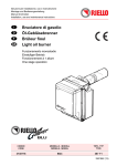
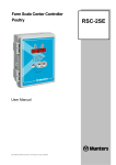
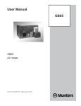
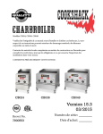
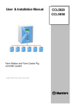
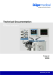
Evaporative
Humidifier/Cooler
FA6 for AHU’s
Technical manual
HC/MMA/TGB-1711-06/10 pdf
SOS ReklamStudio
FA6
Disclaimer
Munters reserves the right to make alterations to specifications, quantities, dimensions etc. for production or other reasons,
subsequent to publication.
The information contained herein has been prepared by qualified experts within Munters.
While we believe the information is accurate and complete, we make no warranty or representation for any particular purposes.
The information is offered in good faith and with the understanding that any use of the units or accessories in breach of the
directions and warnings in this document is at the sole discretion and risk of the user.
This manual has been prepared in English as original language.
© Munters Europe AB 2010
Contents
FA6 Evaporative humidifier/Cooler Introduction
Introduction
Technology basics
Standard sizes
Simple to install
Technical specification
Design and operation
Circulating-water models
Bleed-off flow
Control system
On/off control
Step control
Face and by-pass control
Dew-point control
Options
BMS integration and improved hygiene
4
4
5
5
5
6
7
7
8
9
10
10
11
11
12
FA6 Clean Concept
FA6 Dosing System
FA6 UV sterlilization system
FA6cs Conductivity System
Dimensioning
12
How to select your FA6
Size selection program
Dimensioning example
Charts for Humidifier sizing
Dimensions, weight and pump sizes
Water quality / data
Table and example
Water from other sources
Total water consumption for direct-supply-water model – table
Pressure requirements at water supply connection point without CC unit
Water consumption
13–14
15
16
16
16
16
17
18
Direct water model
Circulating water model
Bleed-off factor
Example
Water quality
18
Water from other sources
General water hardness conversion table
Ordering key
19
Design standards, approvals and certifications
19
3
FA6 Evaporative humidifier/cooler
A
A = Warm and Dry air
B = Cold and Humid air
B
Circulating-water system
Introduction
The Munters evaporative FA6 humidifier/cooler has been specially designed for integration into air-handling units within
both residential and industrial buildings. The design is compact and sizes conform to all typical air handling units (AHU).
The standard product line encompasses a wide range of sizes,
options, for multistage control integrated droplet separator and
three nominal humidity efficiencies of 65%, 85%, 95%.
There are also two different models for either direct water or
circulating water. The airflow range is between 0.5 and 34 m3/s.
The external dimensions of the smallest humidifier are
0.6 x 0.6 m; the largest 3x3 m. The recommended air velocity
through the media is up to 3.5 m/s without the droplet separator (DropSTOP), and up to 4.5 m/s with Dropstop™.
4
Air-flow range, 0.5–34 m3/s
Nominal humidification efficiency: 65%, 85% and 95%
Humidifier cassettes of non combustible GLASdek®
Designed with circulation or direct water systems
With or without droplet separator, DropSTOP™
Adapted for dew-point, stepped, face and by-pass control,
or On-Off control
• Complete emptying of bottom tray
• Simple maintenance
• Comprehensive accessories available.
•
•
•
•
•
•
Technology basics
The heart of FA6 is a cassette made from inorganic non combustible evaporative media – GLASdek®. Water is supplied to
the top of the GLASdek evaporative media via a distribution
header. The water flows down the corrugated surface of the
media. As the warm and dry air passes through the media it
evaporates a proportion of the water and thus produces cold,
humidified air. The rest of the water assists in washing the media, and is drained back to the tray. The energy that is needed
for the evaporation is taken from the air itself. The air that
leaves the humidifier is therefore humidified and cooled simultaneously without any external energy supply for the evaporation. This is in essence the adiabatic cooling process. It is very
efficient and the consumption of energy is very low. It also allows the use of water straight from the tap with no need for
water treatment (i.e. demineralisation plants). Minerals and
pollutants stay behind in the GLASdek evaporative media to
be washed away with the discharge water keeping the total humidification process pure.
The principle of evaporative humidifictaion and cooling
(the adiabatic cooling process).
Standard sizes
Wide range of sizes
FA6 comes in a wide range of standard sizes that conform to
all typical air handling unit dimensions. The individual units
cover air volumes from 0.5-34 m3/s.
For very large air volumes a combination of units is selected
in order to achieve the desired size. Non-standard sizes are
available upon request. Selecting the optimal size is easy with
the FA6 Dimensioning Program or your Munters contact person can help you.
Simple to install
The FA6 is easy to install and easy to configure into both existing and new HVAC systems. For installation you need to have
access to electricity (400V/50 Hz) and (230V/50 Hz) as standard for pump and solenoid valves. Pump for (230V/50 Hz) or
(120V/60 Hz) and solenoid valves for (24V AC) are available
as option.
Water supply (1-10 bar) and drainage (Ø 50 mm/2”). Connect to existing BMS/control system or Munters can supply a
new control system for the control of humidifier/cooler.
Due to its high performance and compact design it is the ideal
replacement for older, less efficient humidifiers/coolers.
B, height [cm]
A, width
[cm]
60
90
120
60
0.9
1.6
2.4
90
1.2
2.3
3.4
120
1.7
150
180
210
240
270
300
Air volume [m3/s at 4.5 m/s]
3.2
4.7
150
3.9
5.8
7.6
9.5
11.3
13.2
180
4.8
7.1
9.3
11.6
13.8
16.0
210
8.1
10.7
13.3
15.9
18.5
240
9.4
12.4
15.4
18.4
21.4
24.4
270
10.5
13.8
17.2
20.5
23.9
27.2
300
11.8
15.5
19.3
23.0
26.7
30.5
34.2
Customized sizes on request are available contact your Munters contact person.
5
Technical specifications
Connection points and access space requirements for service
1.
2.
3.
4.
5.
Electrical data – circulation pump
Sound attenuation*
Pump size
(ref. p. 9)
8 KTF16
9 KTF51
10 KTF81
11 KTF82
Voltage
V ±10%
3-phase
∆230/Y400
3-phase
∆230/Y400
3-phase
∆230/Y400
3-phase
∆230/Y400
Frequency
Hz
Power
W
Rated
current A
50
49
0.26/0.15
50
75
0.38/0.22
50
140
0.71/0.41
50–60
220
0.95/0.55
Supply air
Humidified air
Electrical connection point for pump
Cold-water connection female threaded coupling, 1/2” 18 mm
Discharge pipe with a rubber socket for piping with dimension d=50 mm / 2”.
6. Access for inspection and servicing
Integral attenuation, dB
Octave band Hz
63
125
250
FA6-65
3
2
2
500 1,000 2,000 4,000 8,000
2
4
5
8
10
FA6-85
3
2
2
3
5
6
12
15
FA6-95
3
2
3
3
5
7
13
16
*) Sound level for FA6 unit is not above 70 dB.
Maximum continuous operating temperature
Electrical – solenoid valve for step control
Air
Water
Frequency Hz
Power
W
GLASdek
200 °C
40 °C
Mesh reinforced plastic hose
50 °C
50 °C
1-phase 230 V(AC)
50–60
43/24
PVC pipes
50 °C
50 °C
24 V(AC)
50–60
15
Circulation pump ON
40 °C
80 °C
Circulation pump OFF
75 °C
80 °C
Voltage
V ±10%
Drain capacity
Bottom valve only
30 l/min
Overflow protection only
30 l/min
Bottom valve + overflow protection
60 l/min
Stated drain capacity is valid when using 50mm drain pipes.
6
IP classes
Pump
54
Solenoid valve
65
Drain valve
54
Design and operation
Two different types of systems are available Circulating water or Direct water.
Circulating water FA6 units
A circulating water system is recommended to most applications/sizes to ensure low water consumption and low life cycle
cost.
Direct water FA6 units
Direct water systems are commonly used when the water quality is too poor for circulating systems or when the humidifiers’
annual operation time is short. Direct water system are not
available in all sizes, see chart on page 17.
Circulating-water models
The tray is filled with cold water from the mains and the
water level is maintained by the level switch and solenoid valve.
When there is a demand for humidification, the pump starts
and delivers water to the water distribution assembly where it
is supplied to the water distribution header. Each water distribution header assembly supplies sufficient water to the humidifier cassette. The water then flows down through the corrugated surface of the humidifier cassette. Some of the water is
absorbed by the GLASdek® media and the rest runs down
into the bottom tray. As the supply air passes through the media, a proportion of the water absorbed by the media evaporates on contact with the air to produce humidified air.
Direct-water-supply models
The direct-water model does not have a water pump, therefore
it is essential that the mains cold-water supply connected to
the unit has adequate pressure and flow rate for the humidifier
being installed. Mains cold water is supplied to the unit and is
fed to the water distribution header via a constant flow valve.
The constant flow valve ensures that the correct flow rate is
supplied to the water distribution header of each cassette.
The water flows downward through the corrugated surface of
the humidifier cassette. Some of the water is absorbed by the
GLASdek media and the rest runs down into the bottom
tray. As the supply air passes through the humidifier, a proportion of the water absorbed by the media evaporates on contact
with the air to produce humidified air. The water that reaches
the bottom tray is discharged directly to the wastewater system
through the discharge pipe.
7
Design and operation
Circulating
Direct
2
2
2
1
1
3
7
3
1
5
3
3
9
10
8
4
13
D
2
11
5
C
C
4
6
5
8
12
7
6
D
Function diagram
C Mains Cold-Water
D Discharge Water
1 Humidifier Cassette
2 Water-Distribution Header
Assembly
3 Water-Distribution Hose
4 Level switch
5 Water inlet solenoid valve
6 Reservoir Drain Valve
7 Bleed-off Drain
8 Water-Distribution
Assembly
9 Bleed-off Control Valve
10 Pump
11 Discharge Pipe
12 Overflow Outlet
13 Pressure reduction
Bleed-off flow
Regular cold water from city mains contains a certain amount
of minerals and salts, the concentration of which varies from
place to place. During evaporation, pure water is released to
the air. The minerals and salts remain in the water and are returned to the water reservoir. The concentration in the reservoir water therefore becomes higher than the supply water. If
the mineral concentration (especially calcium) becomes too
high, scale deposits may form on the surface of the media until
they finally clog the humidifier. To combat the problem, a pro-
8
C Mains Cold-Water
D Discharge Water
1 Humidifier Cassette
2 Water-Distribution Header
Assembly
3 Water-Distribution Hose
4 Mains Water Connection
5 Constant Flow Valve
6 Water Distribution
Assembly
7 Discharge Pipe
8 Overflow Outlet
portion of the reservoir water must be drained and replaced
with fresh water. The water that is drained off through the
bleed-off valve via the bleed-off hose to the discharge pipe is
called the bleed-off flow. The bleed-off flow rate is regulated
using the bleed-off valve, so that the mineral concentration is
kept at an acceptable level. Before the humidifier can be started
up, the bleed-off flow rate must be calculated and set in accordance with the instructions on page 18 and in page 13 in FA6
installation/service manual.
Control systems
There are four different Control systems available to control
the humidity.
The FA6 can be easily controlled to address even the most
demanding conditions.
The choice of control method depends mainly on the application and the desired accuracy of the system.
On-Off control system accuracy typical 5-10% relative
humidity RH.
Stage Control controlling the individual cassettes, accuracy
typical 3-5% RH.
Face and By pass the infinitely variable for very exact accuracy 1-2% RH.
Dew point Control measures the absolute humidity of the air
from the humidifier and controls the pre-heater and re-heater
to achieve the set value accuracy 1-2% RH.
GX
On-Off (1-stage)
Stage Control (2-5 stages)
Face and By pass*)
Dew point Control*)
On-off control
Operation
The humidity sensor, GRh, measures the relative humidity in
the room (or exhaust duct) and switches all the cassettes either
on or off, to achieve a humidity level within the set lower and
upper limit values.
The temperature sensor, GT, measures the temperature
downstream of the supply-air fan and controls the preheater, to
achieve the set value.
When humidity is required, the humidifier pump starts and
all the cassettes are supplied with water. The RH level in the
room rises relatively quickly to the set upper limit, since all the
cassettes are in operation. The pump then stops and all the cassettes are taken out of operation. The RH level in the room
then falls, reaching after some time the lower set value. The
pump will then start again, stopping when the upper limit value has been reached.
The operating conditions of the system for varying ambient
air humidity can be found in the ps chart.
Control properties
An on-off control system provides an RH level in the room
during the day that varies between the set maximum and minimum values independent of the humidity of the ambient air.
The system starts and stops several times a day regardless of the
actual humidity of the ambient air. The result in practice is a
control accuracy of ±5-10 percentage points RH.
Operating time
Since the humidifier is greatly over-engineered for
most of the year, the start and stop frequency will be high.
The tighter the set tolerances (start and stop difference), the
higher the start and stop frequency. In times of highly humid
ambient air, the on interval for the humidifier is shorter than
the off interval. When the humidity of ambient air is low,
these conditions are reversed.
GT
GRh
9
Step control
Operation
The humidity sensor, GRh, measures the relative humidity in
the room (or exhaust duct) and opens the necessary solenoid
valves, to achieve a humidity level within the set lower and upper limit values. The temperature sensor, GT (a mean-value
type), measures the temperature downstream of the supply-airfan and controls the preheater, to maintain the set value.
When humidity is required, the humidifier pump starts and
the cassettes without solenoid valves are supplied with water.
The dimensions of these cassettes are chosen so that the RH
level in the room rises to just under the upper set limit value.
If the humidity of the ambient air drops, the RH level in
the room falls. The relative-humidity sensor, GRh, opens the
first solenoid valve when the level has reached the lower limit
value. The size of the cassette for this solenoid has been chosen
so that the RH level now rises again to just under the upper set
limit value.
This sequence is repeated until all the
solenoid valves are open. The operating
conditions of the system for varying ambient air humidity can be found in the ps
chart.
Control properties
A system using step control provides RH level in the room
during the day that varies between the set maximum and minimum values depending on the actual humidity of the ambient
air. Four steps normally provide a control accuracy of ±3-5
percentage points RH. The tighter the tolerances for set maximum and minimum values, the more steps are required.
Operating time
A defined step relates to a certain humidity interval of the ambient air. During the spring, therefore, only one cassette is in
operation. During the winter, four cassettes are in operation.
Please see the diagram. This method of operation will minimize starts and stops. And this will increase the service life of
the cassettes. Furthermore, the operating time for the cassettes
is on average only half of what it is for the cassettes in a dewpoint system.
GT
GRh
Face and by-pass control
Operation
The humidity sensor, GRh, measures the relative humidity in
the room (or exhaust duct) and opens the necessary number of
solenoid valves as well as the face damper, or gradually closes
the by-pass damper, to maintain the set value.
The temperature sensor, GT (a mean-value type), measures
the temperature downstream of the supply-air fan and controls
the preheater, to maintain the set value.
When humidity is required, the humidifier pump starts,
supplying the cassette situated downstream of the face damper.
When the face damper is fully open and there is a continued
demand for humidification, one of the solenoid valves is
opened and the face and by-pass dampers return to their original positions. Should additional humidity continue to be
required, the face damper gradually opens and the by-pass
damper closes to a corresponding degree. When the face
damper has opened completely, the next solenoid opens and
the face and by-pass dampers again return to their original
positions.
This sequence is repeated until all the
solenoid valves have opened. The operating
conditions of the system for varying ambient air humidity can be found in the ps
chart.
10
Control properties
A Face and by-pass system provides an almost constant RH
level in the room during the day regardless of the actual humidity of the ambient air. The result in practice is a control
accuracy of ±1–2 percentage points RH.
Note however that it is not possible to achieve the set
humidity for the room, without pre-cooling, for conditions
whereby the ambient air has a higher wet-bulb temperature
than the room’s wetbulb temperature.
Operating time
This method of operation will minimize starts and stops and
increase the service life of the cassettes. Furthermore, the operating time for the cassettes is on average only half of what it is
for the cassettes in a dew-point system.
The system is highly cost effective compared with dewpoint regulation, since there is no after-heater nor shunt unit.
GT
GRh
Dew point control
Note however that it is not possible to achieve the set humidity
for the room, without pre-cooling, for conditions when the
ambient air is above an imaginary line between the room dew
point and the condition before the humidifier at design ambient air humidity.
Operation
The dew-point sensor GX, measures the absolute humidity of
the air from the humidifier and controls the pre-heater to
achieve the set value.
The temperature sensor, GT, measures the temperature of
the supply air downstream of the inlet fan and controls the
post heater to achieve the set value.
When humidity is required, the humidifier pump starts,
and water is supplied to all the cassettes.
The operating characteristics of the system for varying ambient air humidity can be found in the ps.
chart below.
Operating time
Operation of the unit utilizes all of the humidifier cassettes as
soon as a need for humidity exists.
GX
Control properties
A dew-point system provides an almost
constant Rh level in the room during the
day regardless of the actual humidity of the
ambient air.
The result in practice is a control accuracy
of ±1–2 percentage points RH.
GT
Note A constant interval heat load is assumed for a constant
room temperature. If this is not the case, a room-temperature
sensor should be added.
Options
The customer-order models and accessories below have been
described only briefly.
Please contact your local Munters office for additional information.
Height
The FA6 is available in special heights in case it is necessary to
utilize the maximum height of the air-conditioning unit.
High temperature
Direct water models can be adapted for high temperature
applications (100 °C). Normally used in recirculation paintbooths where high temperatures occur during the drying cycle.
Special cassette sets
Each standard size FA6 has a specific number of 300 mm or
600 mm wide cassettes. For applications requiring close control, two 300 mm cassettes may be used to replace a single 600
mm cassette. Additional solenoid valve must then be installed
for each cassette.
Pump motor and special electrical data
The standard pump has a motor designed for 3-phase,
400V/50 Hz operation or 3-phase 230V/50 Hz. Motors for
3-phase operation using other voltages and/or frequencies are
available, as are motors for 1-phase, 230V/50 Hz and
120/V60 Hz operation.
Constant-flow valves
Specially designed constant-flow valves for systems using direct-water are available. If a humidifier is to be used for indi-
rect evaporative cooling utilizing direct water, the constantflow valves can be designed for half the nominal flow.
Droplet separators
Used to eliminate the risk of carry-over due to high air velocities or turbulent airflow. They are very easy to install and do
not change the FA6 humidifier’s space requirement. Droplet
separators are recommended for all installations with a face velocity over 3.5 m/s.
Total Emptying of water distribution according to
VDI 6022 German requirements.
Direct water units can be ordered with a special designed distribution pipe. The distribution pipe is equipped with motorized drain valve for automatic drainage.
For total emptying of distribution pipes after shutdown.
External pump station
For extra high service availability Munters can supply an external pump station.
Contact your Munters Contact person for details
Control system for step control
Control system for max 6 steps can be supplied.
Number of steps depending on Humidifier size.
Control system for face and Bypass
Control system for max 6 steps and two outputs for damper
actuator can be supplied.
Number of steps depending on Humidifier size.
11
BMS integration and improved hygiene
In most cases water treatments are not necessary, but in cases
with poor water quality, it can be necessary to add a water
treatment.
FA6cc, Clean Concept
A bolt on enhancement for the FA6 humidifier that enables
circulating water models to operate at optimum hygiene levels.
The system incorporates a control panel with BMS connections, electronic level control and automatic drainage of the
reservoir. The system has options for boicide dosing and conductivity controlled bleed-off. FA6cc is designed to exceed current legislation in relation to the control of bacteria in water
systems in many countries – e.g. ACOP L8 in the U.K For
more information, please refer to the FA6cc technical manual.
FA6 Dosing system
The FA6ds, Dosing System is further enhancement of the
FA6cc that enables time controlled, and/or externally controlled, dosing of biocides into the humidifier tray. The system
is supplied with all the necessary parts required for connecting
to the FA6 Evaporative Humidifier/Cooler, excluding the biocide with container.
FA6 UV sterilization system
A recirculating water UV sterilization system kills harmful
bacteria and viruses in water using UV light.
FA6cs, Conductivity System
Enables conductivity controlled bleed-off. The system reduces
water consumption and is especially effective with stage-controlled humidifier/coolers.
Dimensioning
How to select your FA6?
Selection of the right FA6 unit is easy with the advanced FA6
Dimensioning Program.
The program is based on weather data collected over many
years for almost all locations globally. All you need to know are
the following parameters:
• Air volume
• Duct dimensions or the cross-section of the AHU
• Design conditions (location)
• Required control accuracy
• Type of application (Humidification/Cooling)
• Required air conditions
12
FA6 Dimensioning program
A Windows based program is available to help quickly select
the right-sized FA6. The program provides correct humidity
data and other relevant information required for the installation in question. The program can serve as a valuable supplement to this catalogue. Please contact your nearest sales office
for additional information.
Selection of humidifier size
Calculating humidified air
properties: Example
Humidifier airflow range 0.5-4 m3/s
Humidification efficiency η=82%.
Supply air (winter) : t0=-5 °C and x0= 2.0 g/kg.
η, %
100
FA6-95
90
FA6-85
80
t0
t1
t2
°C
x0
x1
x2
g/kg
70
The outside supply air is pre-heated to:
t1=35 °C and x1 = 2.0 g/kg, giving a wet-bulb temperature
of tw=14.6 °C, and a saturated air content of xw=10.4 g/kg
(see psychrometric chart below).
The condition of the humidified air downstream of the
humidifier can be calculated as:
x2 = x1+η/100x (xw-x1) = 2.0+82/100x (10.4-2.0) = 8.9 g/kg
t2 = t1+η/100x (tw-t1) = 35+82/100x (14.6-35) = 18.3 °C
FA6-65
50
20
60
70
30
0
-12
180
80
90
40
0
-12
150
140
100
50
160
180 200
120
60
95%
140
85%
70
25
65%
150-090
0 0
-09 0-12
180 12
q, m3/s
0
0
-12
-15
210
150
120
100
50%
50
80
19
40%
15
40
70
70%
30
4
60
50
30
60%
∆p Pa
40
25
100%
90%
20
80%
60
18
090-120
17
120-090
16
20
3
15
30%
14
2.5
13
12
060-120/
090-090
15
11
10
20
%
9
2
xw
x2
10
8
7
120-060
6
5
060-090
5
10
0
1.5
%
-5
090-060
-1
0
-1
5
4
3
- 10
2
x 0,x 1
1
0
-20
-15
-10
-5
t0
0
5
10
15
20
tw t2
25
30
35
40
t1
1
0.9
060-060
0.8
ok
Definition of humidification efficiency, η %
η=(x2-x1)/(xw-x1)¥100
0.7
0.6
0.5
2.0
2.5
3.0
3.5
4.0
v, m/s
4.5
Example The diagram shows if the selected humidifier is the
FA6-85-090-120 equipped with a droplet separator:
Airflow, q = 2.8 m3/s. Air velocity, v=3.6 m/s. Pressure drop
humidifier, Δp85% = 92 Pa. Pressure drop droplet separator,
Δp = 22 Pa. Humidification efficiency, η=82%
13
Charts for selection of Humidifier sizes
Humidifier airflow range 4-10 m/s
Humidifier airflow range 10-30 m/s
100
h, %
η, %
100
FA6-95
90
FA6-85
80
70
60
60
FA6-65
50
25
30
70
40
15
80
50
20
100
60
70
30
120
80
90
40
140
100
50
160
180 200
120
60
95%
140
85%
70
40
30
15
65%
50
60
40
70
50
20
80
100
60
70
120
80
90
40
30
25
140
100
50
30
160
180 200
120
60
140
95%
85%
70
65%
9
30
027
0
30
030
0
150-180/
240-120
180-150
q, m3/s
24
0-1
50
30
0-1
18 20
0
15 -180
0-2
10
21
027 150
0-1
20
-15
0
21
150-18
0-2 0
40
70
18
0-2
10
/2
30
0-1
0-2
80
10
/21
0-2
40
30
24
24
2 02 7 40
0-2
10
60
20
30
∆p Pa
50
27
0-1
80
18
0-2
4
0
24
0-1 /210
-21
80
/30
0
0-1
50
40
∆p Pa
FA6-65
50
20
q, m3/s
FA6-85
FA6-85
80
70
10
FA6-95
90
270-270
300-240
25
240-270
270-240
210-120
300-210
8
150-150
240-240
270-210
180-120
20
7
300-180
240-210/
210-240
270-180
180-240/
210-210
6
150-120
240-180/
300-150
15
180-210/
270-150
210-180
150-240
5
180-090
240-150
120-120
300-120
180-180
150-210
10
4
2.0
2.5
3.0
3.5
4.0
v, m/s
4.5
Droplet separator recommended for air velocities above 3.5 m/s.
14
2.0
2.5
3.0
3.5
4.0
v, m/s
4.5
Dimensions, weights and pump sizes
Dimensions
mm
A
B
060-060
060-090
060-120
600
600
900
1200
090-060
090-090
090-120
900
600
900
1200
120-060
120-090
120-120
1200
600
900
1200
Size
150-090
150-120
150-150
150-180
150-210
150-240
180-090
180-120
180-150
180-180
180-210
180-240
210-120
210-150
210-180
210-210
210-240
240-120
240-150
240-180
240-210
240-240
240-270
270-120
270-150
270-180
270-210
270-240
270-270
300-120
300-150
300-180
300-210
300-240
300-270
300-300
1500
1800
2100
2400
2700
3000
900
1200
1500
1800
2100
2400
Qty
cassettes
Width Width
300mm 600mm
1
1
900
1200
1500
1800
2100
2400
1200
1500
1800
2100
2400
1
1200
1500
1800
2100
2400
2700
3000
Dry
Wet
Dry
FA6-95
C=730 mm, D=300 mm
Pump size
Weight
kg
Wet
Dry
8
8
8
44
49
52
23
26
28
8
8
8
50
57
64
26
30
33
8
8
9
58
70
80
28
33
38
1
8
8
8
60
66
73
29
32
35
8
8
8
69
78
91
33
38
43
8
8
9
84
100
116
39
46
53
2
8
8
8
76
84
92
35
39
42
8
8
8
88
100
115
41
46
52
9
9
9
106
129
148
48
56
64
8
8
8
8
8
8
103
113
123
134
141
150
48
51
55
60
64
68
8
8
9
9
9
9
124
142
159
178
197
212
56
62
71
79
88
95
9
9
9
9
9
10
159
184
208
237
262
286
67
79
90
102
113
123
8
8
8
8
8
8
118
134
146
158
165
177
50
59
64
70
74
79
8
8
9
9
9
9
142
169
187
210
233
250
61
74
82
92
102
109
9
9
9
10
10
10
185
218
247
281
309
338
76
91
104
118
130
142
8
8
8
8
8
156
169
184
193
206
68
74
81
85
91
9
9
9
9
9
197
219
245
271
292
86
96
108
118
128
10
10
10
10
11
254
288
328
362
395
107
121
138
153
167
8
8
8
8
8
9
175
191
206
216
232
247
75
82
89
94
101
107
9
9
9
9
9
9
221
246
276
306
329
359
95
106
119
131
141
153
10
10
11
11
11
11
286
325
370
407
446
483
118
134
153
169
185
195
8
8
8
8
9
9
197
241
232
244
261
277
84
91
100
106
113
120
9
9
9
9
10
10
250
278
310
345
372
405
107
119
134
148
160
174
10
10
11
11
11
11
323
366
417
461
503
554
133
152
173
192
210
231
8
8
8
8
9
9
9
216
235
254
267
286
305
336
91
99
108
114
122
130
141
9
9
10
10
10
10
10
274
304
341
380
408
445
462
116
129
145
161
173
188
222
11
11
11
11
11
11
11
355
403
459
505
554
610
638
145
164
186
207
227
250
309
2
3
4
1
Wet
FA6-85
C=630 mm, D=200 mm
Pump size
Weight
kg
1
3
1200
1500
1800
2100
2400
2700
1200
1500
1800
2100
2400
2700
FA6-65
C=630 mm, D=100 mm
Pump size
Weight
kg
4
5
Humidifier with height over 210 cm are delivered disassembled.
Upon request other sizes can be delivered disassembled.
15
Water Quality /Data
Following page is based on FA6 with Clean concept control
Total hardness as mg/l Ca 2+
Total alkalinity as mg/l HCO310
20
30
40
50
60
70
80
90
100
125
150
175
200
250
300
350
400
450
500
10
6.0
6.0
6.0
6.0
6.0
6.0
6.0
6.0
6.0
6.0
6.0
6.0
6.0
6.0
6.0
6.0
6.0
6.0
6.0
6.0
20
6.0
6.0
6.0
6.0
6.0
6.0
6.0
6.0
6.0
6.0
6.0
6.0
6.0
6.0
6.0
6.0
5.9
5.7
5.4
5.2
30
6.0
6.0
6.0
6.0
6.0
6.0
6.0
6.0
6.0
6.0
6.0
6.0
5.9
5.6
5.2
4.8
4.6
4.3
4.1
4.0
40
6.0
6.0
6.0
6.0
6.0
6.0
6.0
6.0
6.0
6.0
5.6
5.2
4.9
4.7
4.3
4.0
3.8
3.6
3.4
3.3
50
6.0
6.0
6.0
6.0
6.0
6.0
6.0
5.7
5.5
5.2
4.8
4.5
4.2
4.0
3.7
3.5
3.3
3.1
3.0
2.8
60
6.0
6.0
6.0
6.0
6.0
5.6
5.3
5.1
4.8
4.6
4.3
4.0
3.8
3.6
3.3
3.1
2.9
2.7
2.6
2.5
70
6.0
6.0
6.0
5.9
5.5
5.1
4.8
4.6
4.4
4.2
3.9
3.6
3.4
3.2
3.0
2.8
2.6
2.5
2.4
2.3
Cycles <2: Conductivity controlled
bleed-off not recommended
80
6.0
6.0
6.0
5.4
5.0
4.7
4.4
4.2
4.0
3.8
3.5
3.3
3.1
3.0
2.7
2.5
2.4
2.3
2.2
2.1
90
6.0
6.0
5.6
5.0
4.6
4.3
4.1
3.9
3.7
3.6
3.3
3.0
2.9
2.7
2.5
2.3
2.2
2.1
2.0
1.9
Total hardness (calcium hardness)
°dH × 7.2 ⇒ mg/l Ca2+
°f × 4.0 ⇒ mg/l Ca2+
°clark × 5.7 ⇒ mg/l Ca2+
ppm CaCO3 × 0.25 ⇒ mg/l Ca2+
Total alkalinity (carbonate hardness, bicarbonate)
°dH
ppm CaCO3
ppm NaOH
125
6.0
5.3
4.5
4.1
3.7
3.5
3.3
3.1
3.0
2.9
2.6
2.5
2.3
2.2
2.0
1.9
1.8
1.7
1.6
1.6
150
6.0
4.7
4.0
3.6
3.3
3.1
2.9
2.8
2.6
2.5
2.3
2.2
2.1
2.0
1.8
1.7
1.6
1.5
1.4
1.4
175
5.5
4.2
3.6
3.3
3.0
2.8
2.6
2.5
2.4
2.3
2.1
2.0
1.9
1.8
1.6
1.5
1.4
1.4
1.3
1.2
200
5.0
3.9
3.3
3.0
2.7
2.6
2.4
2.3
2.2
2.1
1.9
1.8
1.7
1.6
1.5
1.4
1.3
1.2
1.2
1.1
250
4.4
3.3
2.9
2.6
2.4
2.2
2.1
2.0
1.9
1.8
1.7
1.6
1.5
1.4
1.3
1.2
1.1
1.1
1.0
1.0
Cycles <1.5: Direct water recommended
The table shows the maximum recommended cycles of concentration for different water qualities. Cycles of concentration =
mineral concentration in humidifier water/mineral concentration in supply water. The cycle value is used to calculate the
bleed off. If the cycle rate is 2 or lower, it is recommended that a
direct water system be used instead of circulating water, or the
supply water should be treated to improve the water quality. The
conversion table below can be used to convert local measuring
units to fit the table.
°dH
°f
°clark
ppm CaCO3
100
6.0
6.0
5.2
4.7
4.3
4.0
3.8
3.6
3.5
3.3
3.0
2.8
2.7
2.6
2.3
2.2
2.1
2.0
1.9
1.8
°dH × 21.8 ⇒ mg/l HCO3–
ppm CaCO3 × 1.2 ⇒ mg/l HCO3–
ppm NaOH × 1.5 ⇒ mg/l HCO3–
Total hardness
Total alkalinity
300
3.9
3.0
2.5
2.3
2.1
2.0
1.8
1.8
1.7
1.6
1.5
1.4
1.3
1.2
1.1
1.1
1.0
1.0
0.9
0.9
350
3.5
2.7
2.3
2.1
1.9
1.8
1.7
1.6
1.5
1.5
1.3
1.2
1.2
1.1
1.0
1.0
0.9
0.9
0.8
0.8
400
3.2
2.5
2.1
1.9
1.7
1.6
1.5
1.5
1.4
1.3
1.2
1.1
1.1
1.0
0.9
0.9
0.8
0.8
0.8
0.7
450
3.0
2.3
1.9
1.7
1.6
1.5
1.4
1.3
1.3
1.2
1.1
1.1
1.0
0.9
0.9
0.8
0.8
0.7
0.7
0.7
500
2.8
2.1
1.8
1.6
1.5
1.4
1.3
1.3
1.2
1.2
1.1
1.0
0.9
0.9
0.8
0.8
0.7
0.7
0.7
0.6
Cycles <1: Non-usable water
80 mg/l Ca2+
100 mg/l HCO3–
• Cycles of concentration from table:
C = 3.6
• Calculate the average evaporation:
E = q × 60 × 1.2 × (x2-x1) / 1,000 = 2.8 × 60 × 1.2 × (9-2) /
1,000 = 1.41 l/min
• Calculate the bleed-off:
B= E / (C-1) = 1.41 / (3.6-1) = 0.54 l/min
• The total water consumption can be calculated:
T = E + B = 1.41 + 0.54 = 1.95 l/min
Water from other sources
If the supply water is not classified as drinking water from the
mains the following additional concentration limits are recommended.
Chlorides (mg/l Cl–)
Sulphates ( mg/l SO42–)
Bacteria rate (CFU/ml, KBE/ml)
Cl– × C < 200 mg/l
SO42– × C < 300 mg/l
CFU/ml × C < 1000
General
Concentration
Conductivity
mg/l = g/m3 = ppm
1mS/m = 10 μS/cm = 10 μMHO
The total water consumption (T) is the sum of the evaporated
water quantity (E) and the bleed-off quantity (B). When estimating the evaporated water quantity, use the average running
conditions for the installation.
Example
Airflow
Average moisture content of supply air
Average moisture content of humidified air
16
q = 2.8 m3/s
x1 = 2.0 g/kg
x2 = 9.0 g/kg
Multiply the concentration by the cycle ratio (C) and compare
to the recommended limit. If the value is over the limit, reduce
the cycle rate.
When using softened water, the total hardness can’t be used
for dimensioning the bleed-off. Instead use a conductivity limit
of 1,000 μS/cm to calculate the cycle ratio. Supply conductivity
× C <1,000 μS/cm.
In poor water quality areas, a blend of treated water and raw
water can be used to lower the mineral content. The water
should be blended so that the conductivity >100 μS/cm. If the
blended water is too clean it may leech the minerals out of the
GLASdek®‚ cassettes and thereby seriously damage them.
Total water consumption (T) for direct-supply-water
model
Models
060-060
060-090
060-120
090-060
090-090
090-120
120-060
120-090
120-120
150-090
150-120
150-150
150-180
150-210
150-240
180-090
180-120
180-150
180-180
180-210
180-240
210-120
210-150
210-180
210-210
210-240
240-120
240-150
240-180
240-210
240-240
240-270
270-120
270-150
270-180
270-210
270-240
270-270
300-120
300-150
300-180
300-210
300-240
300-270
300-300
FA6-65
T
l/min
1.8
1.8
1.8
2.8
2.8
2.8
3.5
3.5
3.5
4.5
4.5
4.5
6.3
8.0
8.0
6.3
6.3
6.3
8.0
8.0
10.0
6.3
6.3
8.0
10.0
12.0
8.0
8.0
10.0
12.0
12.0
15.0
10.0
10.0
10.0
12.0
15.0
15.0
10.0
10.0
12.0
15.0
18.0
18.0
FA6-85
T
l/min
3.5
3.5
3.5
6.3
6.3
6.3
8.0
8.0
8.0
10.0
10.0
10.0
10.0
12.0
15.0
12.0
12.0
12.0
12.0
15.0
15.0
15.0
15.0
15.0
15.0
18.0
15.0
15.0
15.0
18.0
FA6-95
T
l/min
3.5
3.5
3.5
6.3
6.3
6.3
8.0
8.0
8.0
10.0
10.0
10.0
12.0
15.0
18.0
12.0
12.0
12.0
15.0
18.0
18.0
18.0
18.0
18.0
18.0
18.0
18.0
18.0
18.0
Pressure requirements at water supply connection
point
Pressure requirements
Required min. pressure at
connection point
Circulating
water
500 kPa*
(5.0 bar)
Direct
water
150 kPa
(1.5 bar)
Permitted max. pressure at
connection point
1,000 kPa
(10.0 bar)
1,000 kPa
(10.0 bar)
Circulating water model
The total water consumption is the sum of evaporated water
and the bleed-off. The bleed-off is a constant discharge flow
that is necessary to maintain the mineral concentration in the
tray at such a level that the service life of the humidifier cassettes may be optimised. The recommended amount of bleedoff depends on the quality of the supply water. If the water
quality is not known a water analysis may be carried out, but it
is often simpler to ask the local water company for analysis
data. Based on tests performed and operating evaluations of
various systems, Munters has established the following recommendations see page 18.
15.0
15.0
18.0
15.0
15.0
Special design with increased draining capacity is required.
17
Water consumption
Direct water
The total water consumption is a sum of the total number of
running hours.The table in page 17 specifies the maximum water
consumption (l/min) when water supply is on.
Circulating water model
The total water consumption is the sum of the evaporated water
(E) and the bleed-off amount (B). The bleed-off is the constant
discharge flow that is necessary to maintain the mineral
concentration in the circulating water at such a level that the
service life of the FA6 humidification cooling pad is optimised.
Bleed-off factor
The bleed-off factor (B) is obtained from the quality diagram
below if the water quality is known. A water analysis may be
carried out, but it is often simpler to ask the local water company for analysis data.
If the bleed-off factor is above 2, it is recommended that a
25
250
Example
Airflow
Average moisture content of supply air
Average moisture content of humidified air
Total hardness
Total alkalinity
• Bleed-off factor from table: fB = 0.3
• Calculate the average evaporation:
E = q × 60 × 1.2 × (x2-x1) / 1,000 = 2.8 × 60 × 1.2 × (9-2) /
1,000 = 1.41 l/min
• Calculate the bleed-off: B = fB x E = 0.3 x 1.41 = 0.42 l/min
• The total water consumption can be calculated:
T = E + B = 1.41 + 0.42 = 1.83 l/min
CaCO3 mg/l
2,500
25,000
HCO3- mg/l
10
100
1,000
10
,00
0
Ca2+ mg/l
1.0
q = 2.8 m3/s
x1 = 2.0 g/kg
x2 = 9.0 g/kg
100 mg/l Ca2+
100 mg/l HCO3–
10,000
1,0
00
2.5
direct water system is used instead of circulating water, or the
water supply should be treated to improve the water quality.
fB
0.5
0.1
fa
ct
or
10
w
at
er
10
1.0
(n Dire
ot c
ci t-w
rc a
ul te
at r
in
g)
1.0
0.2
5
2
1.0 .0
CO2-3 mg/l
No
nus
ab
le
10
0
100
0.1
0.01
6
7
8
Quality diagram for water.
9
pH
Water quality
Water from other sources
If the supply water is not classified as drinking water from the
mains the following additional concentration limits are
recommended.
Chlorides (mg/l Cl–)
Sulphates (mg/l SO42–)
Cl– × C < 200 mg/l
SO42– × C < 300 mg/l
Bacteria rate (CFU/ml, KBE/ml)
CFU/ml × C < 1000
Multiply the concentration by the cycle ratio (C) and compare to
the recommended limit. If the value is over the limit, reduce the
cycle rate.
When using softened water, the total hardness can’t be used for
dimensioning the bleed-off. Instead use a conductivity limit of
1000 µS/cm to calculate the cycle ratio. Supply conductivity × C
<1000 µS/cm.
18
General water hardness conversion table CaCO3
Hardness [dH]
CaCO3 [mg/l]
Very soft
0–2
0–36
Soft
2–5
36–90
Normal
5–10
90–179
Hard
10–21
179–376
>21
>376
Water condition
Very hard
In poor water quality areas, a blend of treated water and raw
water can be used to lower the mineral content. The water should
be blended so that the conductivity >100 µS/cm. If the blended
water is too clean it may leech the minerals out of the GLASdek®‚
cassettes and thereby seriously damage them.
Ordering key
FA6-EE-WWW-HHH-XX-X-X
Code for humidification efficiency
65 = 65%
85 = 85%
95 = 95%
Code for width, cm
See page 20
Code for height, cm
See page 20
Code for water system
C = Circulating water
D = Direct water
CS = Face and bypass
1-5= no. of steps 1)
Code for droplet separator
0 = Without
1 = With
Code for service and pipe-connection side
L = Left
R = Right
Comments
Humidifiers with height over 210 cm are delivered disassembled.
Upon request other size can be delivered disassembled.
The standard delivery does not include, water filter or water trap
these parts can be ordered as accessories.
1)
When the number of steps = 1, no solenoid valve is included
for step control.
In the case of more steps than one, the number of solenoid
valves depends on the number of cassettes in the humidifier. Your
contact person at Munters will be able to furnish you with full
details.
Left
Right
Service and pipe connection side
e.g., FA6-85-120-090-C1- 0-L
Design standards, approvals and certifications
FA6 humidifier/Cooler is manufactured in accordance with the
following Harmonized European standards and technical
specifications.
• EN 60204-1 edition 3 Safety of machinery, electrical
equipment of machines.
• EN 61000-6-3 edition 1 Electromagnetic compability EMC
Emissions standard for Residential, commercial and lightindustrial environments.
• EN 61000-6-3/A11 Electromagnetic compability EMC
Emissions standard for Residential, commercial and lightindustrial environments.
• EN 61000-6-1 Electromagnetic compability EMC Emissions
standard for Residential, commercial and light-industrial
environments.
It agrees, with the limitations that have been stipulated for
machines, with the most important health and safety requirements
of Machinery Directive 2006/42/EG and furthermore
2004/108/EC with guideline for Electromagnetic compability.
Humidifier cassette
The glass-fiber material GLASdek® used for the humidifier
cassette has been fire tested and classified as non-combustible
material according to the test standard ISO 1182. The glass-fiber
material GLASdek® used for the droplet separator cassette has
been fire tested and classified as nonflammable material class 1,
according to BS 476: part 7, M1 according to the French CSTB,
and class T1 according to JISA 1322, Japan. This corresponds to
NordTestFire 004, class 1, and the German DIN 4102, part 1, class
B1 in accordance with Svensk Standard (Swedish Standard)
SS28418.
Selection of materials
The major standard components of the Munters FA6 humidifier and their materials of construction are listed below.
• The frame, cassette profiles, pump bracket, pump filter,
water distribution headers and bottom trough are manufactured from stainless steel, EN 1.4301.
• The humidifier cassettes and droplet separator are of
nonflammable glass-fiber, GLASdek®.
• The water-distribution has PVC tubing.
• The water-distribution hoses are of mesh-reinforced soft
plastic with PVC couplings.
• The circulation pump impeller and pump housing are of
plastic (PPS).
• The constant flow valve is of brass.
• Discharge pipe is of polyethylene tubing.
19
Australia Munters Pty Limited, Phone +61 2 6025 6422, Brazil Munters Brasil Industria e Comercio Ltda, Phone +55 41 3317 5050, Canada Munters Incorporated, Phone +1 905 858 5894,
China Munters Air Treatment Equipment (Beijing) Co. Ltd., Phone +86 10 80 481 121, Denmark Munters Turbovent, Phone +45 9862 3311, Finland Munters Oy, Phone +358 9 83 86 030,
France Munters France S.A., Phone +33 1 34 11 57 50, Germany Munters Euroform GmbH, Phone +49 241 89 00 0, India Munters India, Phone +91 20 3052 2520, Indonesia Munters, Phone +62 818 739 235,
Italy Munters Italy S.p.A., Chiusavecchia Phone +39 0183-52 11, Munters Italy S.p.A., Mondovì Phone +39 0174 560 600, Japan Munters K.K., Phone +81 3 5970 0021,
Kingdom of Saudi Arabia and Middle East Hawa Munters, Phone +966 1 241 8808, Korea Munters Korea Co. Ltd., Phone +82 2 761 8701, Mexico Munters Mexico, Phone +52 818 262 54 00,
Russia Munters Europe AB, Phone +7 812 448 5740, Singapore Munters Pte Ltd., Phone +65 744 6828, South Africa and Sub-Sahara Countries Munters (Pty) Ltd., Phone +27 11 997 2000,
Spain Munters Spain S.A., Phone +34 91 640 09 02, Sweden Munters Europe AB, Phone +46 8 626 63 00, Thailand Munters Co. Ltd., Phone +66 2 645 2708 12, Turkey Munters Form Endüstri Sistemleri A.Ş,
Phone +90 322 231 13 38, United Kingdom Munters Ltd., Phone +44 845 644 3980, USA Munters Corporation Fort Myers Phone +1 239 936 1555, Munters Corporation Mason Phone +1 888 335 0100,
Vietnam Munters Vietnam, Phone +84 8 825 6838, Export & Other countries Munters Europe AB, Phone +46 8 626 63 00.
© Munters AB, 2010
GLASdek® and FA6TM are trademarks of Munters.
Munters Europe AB, HumiCool Division, Isafjordsgatan 1, P.O. Box 1150, SE-164 26 Kista, Sweden. Phone +46 8 626 63 00, Fax +46 8 754 56 66.
www.munters.com