1
3.
INSTALLATION
THE BURNER MUST BE INSTALLED IN CONFORMITY WITH LEGISLATION AND LOCAL STANDARDS.
3.1 BOILER FIXING
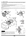
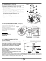
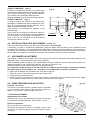
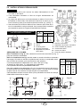
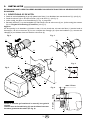
➤ Insert the recirculating pipe (6) in the flange seat (1) and lock with the screw (7), (see fig. 2).
➤ Put on the flange (1) the screw (9) and two nuts (10), (see fig. 3).
➤ Widen, if necessary, the insulating gasket holes (5, fig. 4).
➤ Fix the flange (1) to the boiler door (4) using screws (2) and (if necessary) the nuts (3) interposing the
insulating gasket (5), (see fig. 5).
Warning:
If the hole in the boiler door (4) is less than 110 mm, before fixing the flange (1) to the boiler, unscrew the
three screws (8) and remove the recirculating pipe (6). Open the boiler door (4), fit the recirculating pipe (6)
and fix it with the three screws (8).
Fig. 2
Fig. 3
9
7
6
10
E9060
8
1
1
E9059
3
5
Fig. 4
Fig. 5
2
5
D5012
4
1
max. 110 mm
2
E9061
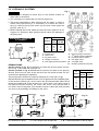
WARNING
Verify that the installed burner is lightly leaned towards
the button.
In order to allow this operation, the insulating gasket
(5) must be installed with the higher thickness faced
down (see fig. 6).
2900
3
GB
ø as
EN226
Fig. 6
5
D1959