1
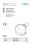
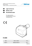
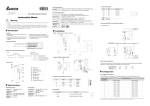
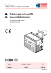
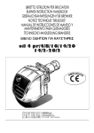
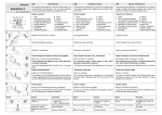
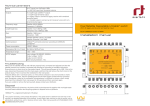
Installation, use and maintenance instructions
Manuel d’entretien
Installatie-, gebruiks- en onderhoudsvoorschriften
GB
F
NL
Oil burners
Brûleurs fioul
Stookoliebranders
One stage operation
Fonctionnement à 1 allure
Eentrapsbranders
CODE
MODEL - MODELE
TYPE
8099000
SIME MACK 3
514 T1R
8099010
SIME MACK 4
515 T3R
8099030
SIME MACK 5
515 T5R
2902683 (0)
4
INDEX
1.
BURNER DESCRIPTION . . . . . . . . . . . . . 1
4.
WORKING . . . . . . . . . . . . . . . . . . . . . . .
6
1.1
Burner equipment . . . . . . . . . . . . . . . . . . 1
4.1
Combustion adjustment. . . . . . . . . . . . . .
6
4.2
Nozzles recommended . . . . . . . . . . . . . .
6
2.
TECHNICAL DATA . . . . . . . . . . . . . . . . . 2
4.3
Electrodes setting . . . . . . . . . . . . . . . . . .
7
2.1
Technical data . . . . . . . . . . . . . . . . . . . . . 2
4.4
Air damper adjustment . . . . . . . . . . . . . .
7
2.2
Working fields . . . . . . . . . . . . . . . . . . . . . 2
4.5
Pump pressure . . . . . . . . . . . . . . . . . . . .
7
2.3
Overall dimensions . . . . . . . . . . . . . . . . . 3
4.6
Fuel heating . . . . . . . . . . . . . . . . . . . . . .
7
4.7
Burner start-up cycle. . . . . . . . . . . . . . . .
8
5.
MAINTENANCE . . . . . . . . . . . . . . . . . . .
8
6.
FAULTS / SOLUTIONS . . . . . . . . . . . . . .
9
3.
INSTALLATION . . . . . . . . . . . . . . . . . . . . 3
3.1
Boiler fixing . . . . . . . . . . . . . . . . . . . . . . . 3
3.2
Hydraulic systems . . . . . . . . . . . . . . . . . . 4
3.3
Electrical wiring . . . . . . . . . . . . . . . . . . . . 5
1. BURNER DESCRIPTION
One stage light oil burner.
■
■
The burner meets protection level of IP 40, EN 60529.
Burner with CE marking in conformity with EEC directives: EMC 89/336/EEC, Low Voltage 73/23/EEC,
Machines 98/37/EEC and Efficiency 92/42/EEC.
Fig. 1
3
2
4
7
5
6
5
1
D6272
1 – Oil pump
5 – Screws fixing air-damper
2 – Control-box
6 – Flange with insulating gasket
3 – Reset button with lock-out lamp
7 – Grommet
4 – Hydraulic jack with air-damper
1.1 BURNER EQUIPMENT
Flange with insulating gasket . . . .No. 1
Screws and nuts for flange to be fixed to boiler . . No. 4
Screw and nuts for flange . . . . . .No. 1
Flexible oil pipes with nipples . . . . . . . . . . . . . . . . No. 2
Grommet . . . . . . . . . . . . . . . . . . .No. 1
7 pin plug . . . . . . . . . . . . . . . . . . . . . . . . . . . . . . . No. 1
2683
1
GB
2. TECHNICAL DATA
2.1 TECHNICAL DATA
Model
MACK 3
MACK 4
MACK 5
Output
kg/h
1.4 – 2.2
2.0 – 3.2
2.8 – 3.9
Thermal power
kW
16.6 – 26
23.8 – 37.9
33.3 – 46.2
(Hi = 11.86 kWh/kg)
Light oil, max. viscosity at 20°C: 6 mm2/s
Fuel
Electrical supply
Single phase,
Motor
Run current 0.7 A
~ 50Hz
–
230 V ± 10%
2850 rpm
–
298 rad/s
4 µF
Capacitor
Ignition transformer
Secondary 8 kV
Pump
–
16 mA
Pressure: 7 – 15 bar
Absorbed electrical power
0.165 kW
0.185 kW
2.2 WORKING FIELDS (as EN 267)
Pressure in the combustion
chamber – mbar
0.8
0.6
0.4
MACK 3
0.2
0
1.2
1.4
1.6
1.8
2
2.2
2.4 Light oil output – kg/h
D6282
16
18
20
22
24
26
Thermal power – kW
28
Pressure in the combustion
chamber – mbar
1.2
1.0
0.8
0.6
0.4
MACK 4
MACK 5
0.2
0
2
2.2
2.4
2.6
2.8
31
33
3
3.2
3.4
3.6
3.8
4 Light oil output – kg/h
D6283
23
25
27
29
35
37
39
2683
2
GB
41
43
45
47
Thermal power – kW
2.3 OVERALL DIMENSIONS
Flange
Burner
180
A
=
C
45°
72
F
B
72
11
45 °
øE
91
D
=
130
D6262
G
150
D5908
A
B
C
D
øE
F
G
MACK 3
268
229
208
86
89
170
10
MACK 4 - MACK 5
285
249
230
86
89
186
16
Model
3. INSTALLATION
3.1 BOILER FIXING
➤ Put on the flange (1) the screw and two nuts, (see fig. 2).
➤ Widen, if necessary, the insulating gasket holes (5).
➤ Fix the flange (1) to the boiler door (4) using screws (2) and (if necessary) the nuts (3) interposing the
insulating gasket (5), (see fig. 3).
4
5
Fig. 2
3
Fig. 3
2
E9131
1
1
2
E9132
2683
3
GB
3.2 HYDRAULIC SYSTEMS
The burner is designed to allow entry of the flexible oil-lines on either side of the burner.
WARNING:
Fig. 4
7
■ It is necessary to install a filter on the fuel supply line.
The standard filter code 6276200 and that one with recirculation
code 6276201 are available on request.
6
■ The pump is designed to allow working with two pipes.
5
In order to obtain one pipe working it is necessary to unscrew the
return plug (2), remove the by-pass screw (3) and then screw
again the plug (2), (see fig. 4).
■ Before starting the burner make sure that the return pipe-line is
not clogged. An excessive back pressure would cause the
damage of the pump seal.
L meters
H
meters
I. D.
8 mm
I. D.
10 mm
10
20
40
60
20
40
80
100
0.5
1
1.5
2
H
max. 4 m
SYSTEM NOT
PERMITTED
IN GERMANY
Fig. 5
D6284
4
3
8
1
2
3
4
5
6
7
8
Suction line
Return line
By-pass screw
Gauge connection
Pressure adjuster
Suction gauge connection
Oil valve
Auxiliary pressure test point
H
meters
0
0.5
1
1.5
2
3
3.5
max. 4 m
H
max. 4 m
-
Fig. 6
L meters
I. D.
I. D.
8 mm 10 mm
100
100
100
90
70
30
20
35
30
25
20
15
8
6
Fig. 7
H
H
2
D5912
PRIMING PUMP:
On the system in fig. 5 it is sufficient to loosen the suction gauge
connection (6, fig. 4) and wait until oil flows out.
On the systems in fig. 6 and 7 start the burner and wait for the priming.
Should lock-out occur prior to the arrival of the fuel, await at least 20 seconds
before repeating the operation.
The pump suction should not exceed a maximum of 0.4 bar (30 cm Hg).
Beyond this limit gas is released from the oil. Oil pipes must be completely tight.
In the vacuum systems (fig. 7) the return line should terminate within the oil tank
at the same level as the suction line. In this case a non-return valve is not required. Should however the return line arrive over the fuel level, a non-return
valve is required.
This solution however is less safe than previous one, due to the possibility of
leakage of the valve.
H
1
D6285
H = difference of level;
L = max. length of the suction line;
2683
4
GB
I. D. = internal diameter of the oil pipes.
3.3 ELECTRICAL WIRING
NOTES:
– Wires of 1 mm2 section.
– The electrical wiring carried out by the installer
must be in compliance with the rules in force in the
Country.
WARNING
DO NOT EXCHANGE NEUTRAL WITH PHASE
~ 50Hz
230V
PE
N
L
TESTING
Check the shut-down of the
burner by opening the thermostats.
Main switch
T6A
Hour counter
(230V - 0.1A max.)
Regulating
thermostat
Limit thermostat
with manual
resetting
Remote lock-out lamp
(230V - 0.5A max.)
CONTROL BOX
To remove the control-box
from the burner, loosen screw
(A, fig. 8) and pull to the arrow
direction, after removing all
components, the 7 pin plug
and earth wire.
Fig. 8
7 pin plug
Start thermostat
Heater
555SE
CONTROL BOX
CARRIED-OUT IN THE FACTORY
7 pole socket
Black
White
Motor
Capacitor
Blue
E9040
Oil valve
A
Burner-earth
Ignition
electrodes
Fig. 9
Photoresistance
D1847
ACCESS TO THE PHOTORESISTANCE
(See fig. 9)
Ignition
trasformer
The photoresistance is fitted directly into the control-box (underneath the ignition-transformer) on a
plug-in support.
E9102
Photoresistance
2683
5
GB
4. WORKING
4.1 COMBUSTION ADJUSTMENT
In conformity with Efficiency Directive 92/42/EEC the application of the burner on the boiler, adjustment and testing must be carried out observing the instruction manual of the boiler, including verification of the CO and CO2
concentration in the flue gases, their temperatures and the average temperature of the water in the boiler.
To suit the required appliance output, fit the proper nozzle, then adjust the pump pressure and the air damper opening in accordance with the following table.
■ ADJUSTMENTS CARRIED OUT IN FACTORY FOR SIME BOILERS
The values shown in the table are measured on a SIME boiler (as per EN 267).
They refer to 12.5% CO2 at sea level and with light oil and room temperature of 20 °C.
Table B
BURNER
BOILER
Nozzle
Pump
pressure
Burner
output
Air damper
adjustment
Code
Model
GPH
Angle
bar
kg/h ± 4%
Set-point
Rondò-Estelle 3
8099000
MACK 3
0.55
60° S
12
2.1
3.7
Rondò-Estelle 4
8099010
MACK 4
0.75
60° W
12.5
2.9
2.9
Rondò-Estelle 5
8099030
MACK 5
0.85
60° W
14
3.5
3.8
MACK 5
MACK 4
MACK 3
Model
■ APPROXIMATE ADJUSTMENTS FOR INSTALLATION ON OTHER BOILERS
The values shown in the table are measured on a CEN boiler (as per EN 267).
They refer to 12.5% CO2 at sea level and with light oil and room temperature of 20 °C.
Nozzle
Pump
pressure
Burner
output
Air damper
adjustment
GPH
Angle
bar
kg/h ± 4%
Set-point
0.40
80°
10
1.4
1.7
0.40
80°
12
1.5
1.8
0.50
60°
12
1.9
2.4
0.55
60°
13
2.2
3.5
0.55
60°
11
2.0
1.6
0.60
60°
12
2.3
1.7
0.65
60°
12
2.5
2.2
0.75
60°
12
2.9
2.5
0.85
60°
11.5
3.2
3.2
0.75
60°
11.5
2.8
2.2
0.85
60°
12
3.3
2.5
1.00
60°
12.5
3.9
3.6
3
5
4
1
6
E9155
4.2 NOZZLES RECOMMENDED:
Monarch type R - NS ;
Steinen type H - Q ;
Fig. 10
2
Delavan type W-E
Danfoss type H - S.
MAINTENANCE POSITION
Access to the combustion head, electrodes and nozzle, (see fig. 10).
➤ Remove the burner out of the boiler, after loosing the fixing nut to the flange.
➤ Hook the burner to the flange (1), by removing the combustion head (2) after loosing the fixing screws (3).
➤ Remove the electrodes assembly (5) from the nozzle-holder (4) after loosing its fixing screw (B, fig. 11,
page 7).
➤ Screw the nozzle (6).
2683
6
GB
4.3 ELECTRODES SETTING
ATTENTION
Fig. 11
4 ± 0.3 mm
IMPORTANT:
THESE DIMENSIONS
MUST BE OBSERVED
Before removing or assembling the
nozzle, loosen the screw (B, fig. 11)
and move the electrodes ahead.
D5230
B
2 – 2.5 mm
4.4 AIR DAMPER ADJUSTMENT, (see fig. 12)
The mobile air damper (1) operated by the jack (2) assures the complete opening of the air intake.
The regulation of the air-rate is made by adjusting the fixed air
damper (3), after loosing the screws (4). When the optimal regulation is reached, screw tight the screws (4) to assure a free movement of the mobile air damper (1).
The settings, indicated in the table (page 6), refer to the burner with
its cover fitted and combustion chamber with depression zero.
These regulations are purely indicative.
Each installation however, has its own unpredictable working conditions: actual nozzle output; positive or negative pressure in the combustion-chamber, the need of excess air, etc.
All these conditions may require a different air-damper setting.
Fig. 12
1
2
3
4
It is important to take account of the fact that the air output
of the fan differs according to whether the burner has its
cover fitted or not. Therefore we recommended to proceed as
4
D6286
follows:
➤ Adjust the air damper as indicated in the table.
➤ Mount the cover.
➤ Check smoke number and CO2.
➤ Should it become necessary to modify the air output, remove the cover by loosening the screw, adjust
the air damper, remount the cover and finally recheck the smoke number.
4.5 PUMP PRESSURE:
The pump is set in factory according to the value indicated in the table B at page 6.
4.6 FUEL HEATING
In order to assure regular ignition and working also at low temperatures the burner has an oil pre-heater fitted in combustion head. The pre-heater starts when thermostats close and it is indicated by the ignition of
an orange led placed on the control box.
When the required temperature for ignition is reached the thermostat fitted on the nozzle holder starts the
burner the orange led switches off, the green led switches on and the motor starts. The pre-heater remains
energised during working and cuts out when burner shuts-down.
2683
7
GB
4.7 BURNER START-UP CYCLE
Normal
Lock-out due to failure to light
C
Thermostat
Heater
Orange led
Green led and motor
Ignition transformer
Oil valve
Flame
Lock-out lamp
~120 s
C
~12 s
~120 s
~12 s
~5 s
D5927
Lock out is indicated by a lamp on the control box (3, fig. 1, page 1).
5. MAINTENANCE
Burner requires a periodic maintenance carried out by a qualified and authorized technicians.
Maintenance is essential for the reliability of the burner, avoiding the excessive consumption of fuel and
consequent pollution.
Before carrying out any cleaning or control always first switch off the electrical supply to the
burner acting on the main switch of the system.
THE BASIC CHECKS ARE:
➤ Check that there are not obstructions or dents in the supply or return oil pipes.
➤ Clean the filter in the oil suction line and in the pump.
➤ Clean the photoresistance, (see fig. 9, page 5).
➤ Check for correct fuel consumption.
➤ Replace the nozzle (see fig. 10, page 6) and check the correct position of electrodes (fig. 11, page 7).
➤ Clean the combustion head in the fuel exit area, on the diffuser disc.
➤ Leave the burner working without interruptions for 10 min. and set rightly all the components stated in
this manual. Then carry out a combustion check verifying:
● Smoke temperature at the chimney;
● Content of CO2 ( % );
● Content of CO (ppm);
● Smoke value according to opacity smokes index according to Bacharach scale.
2683
8
GB
6. FAULTS / SOLUTIONS
Here below you can find some causes and the possible solutions for some problems that could cause a failure to start or a bad working of the burner.
A fault usually makes the lock-out lamp light which is situated inside the reset button of the control box
(3, fig. 1, page 1).
When lock out lamp lights the burner will attempt to light only after pushing the reset button. After this if the
burner functions correctly, the lock-out can be attributed to a temporary fault.
If however the lock out continues the cause must be determined and the solution found.
FAULTS
POSSIBLE CAUSES
SOLUTION
Check presence of voltage in the
L1 - N clamps of the 7 pin plug.
All led are off and
the burner does not
start.
Lack of electrical supply.
Check the conditions of the fuses.
Check that thermostat limit is not
lock out.
The connections in the control box are
wrongly inserted.
Check and connect completely all the
plugs.
The orange led is always on and the
burner does not
start.
Heater and start thermostat are faulty.
Replace them.
The green led is on
and the burner remains in the prepurge phase.
The photoresistance sees false light.
Eliminate the light.
The photoresistance is dirty.
Clear it.
The photoresistance is defective.
Change it.
Burner runs normally in the prepurge
and ignition cycle
and locks out after 5
seconds ca.
Check pressure and output of the fuel.
Check air output.
Flame moves away or fails.
Change nozzle.
Check the coil of solenoid valve.
Burner starts with an
ignition delay.
The ignition electrodes are wrongly
positioned.
Adjust them according to the
instructions of this manual.
Air output is too high.
Set the air output according to the
instructions of this manual.
Nozzle dirty or worn.
Replace it.
WARNING
The manufacturer cannot accept responsibility for any damage to persons, animals or property due to error in
installation or in the burner adjustment, or due to improper or unreasonable use or non observance of the
technical instruction enclosed with the burner, or due to the intervention of unqualified personnel.
2683
9
GB
SOMMAIRE
1.
DESCRIPTION DU BRULEUR . . . . . . . . . 1
4.
FONCTIONNEMENT. . . . . . . . . . . . . . . .
6
1.1
Matériel fourni . . . . . . . . . . . . . . . . . . . . . 1
4.1
Réglage de la combustion . . . . . . . . . . . .
6
4.2
Gicleurs conseillés . . . . . . . . . . . . . . . . .
6
2.
DONNEES TECHNIQUES . . . . . . . . . . . . 2
4.3
Réglage des électrodes. . . . . . . . . . . . . .
7
2.1
Données techniques . . . . . . . . . . . . . . . . 2
4.4
Réglage volet d’air . . . . . . . . . . . . . . . . .
7
2.2
Plages de travail. . . . . . . . . . . . . . . . . . . . 2
4.5
Pression pompe . . . . . . . . . . . . . . . . . . .
7
2.3
Dimensions . . . . . . . . . . . . . . . . . . . . . . . 3
4.6
Réchauffage du combustible . . . . . . . . . .
7
4.7
Programme de mise en marche. . . . . . . .
8
5.
ENTRETIEN . . . . . . . . . . . . . . . . . . . . . .
8
6.
PANNES / REMEDES . . . . . . . . . . . . . . .
9
3.
INSTALLATION . . . . . . . . . . . . . . . . . . . . 3
3.1
Fixation à la chaudière . . . . . . . . . . . . . . . 3
3.2
Installations hydrauliques . . . . . . . . . . . . . 4
3.3
Raccordements électriques . . . . . . . . . . . 5
1. DESCRIPTION DU BRULEUR
Brûleur de fioul domestique à fonctionnement à une allure.
■ Brûleur conforme au degré de protection IP 40 selon EN 60529.
■ Brûleur avec label CE conformément aux directives CEE: EMC 89/336/CEE, Basse Tension 73/23/CEE,
Machines 98/37/CEE et rendement 92/42/CEE.
Fig. 1
3
2
4
7
1
2
3
4
–
–
–
–
5
6
5
1
D6272
Pompe fioul
Boîte de commande et de contrôle
Bouton de réarmement avec signalisation de sécurité
Vérin volet d’air
5 – Vis blocage volet d’air
6 – Bride avec joint isolant
7 – Presse-étoupe
1.1 MATERIEL FOURNI
Bride avec joint isolant . . . . . . . . . N° 1
Vis et écrous pour bride de montage sur la chaudière
N° 4
Vis et écrous pour bride . . . . . . . . N° 1
Flexibles avec nipples. . . . . . . . . . . . . . . . . . . . . . . . .
N° 2
Presse-étoupe . . . . . . . . . . . . . . . N° 1
Fiche à 7 pôles . . . . . . . . . . . . . . . . . . . . . . . . . . . . . .
N° 1
2683
1
F
2. DONNEES TECHNIQUES
2.1 DONNEES TECHNIQUES
Modèle
MACK 3
MACK 4
MACK 5
Débit
kg/h
1,4 ÷ 2,2
2,0 ÷ 3,2
2,8 ÷ 3,9
Puissance thermique
kW
16,6 ÷ 26
23,8 ÷ 37,9
33,3 ÷ 46,2
(Hi = 11,86 kWh/kg)
Fioul domestique, viscosité max. à 20°C: 6 mm2/s (1,5 °E)
Combustible
Alimentation électrique
Monophasée,
Moteur
0,7A absorbés
~ 50Hz
230V ± 10%
– 2850 t / min
–
298 rad/s
4 µF
Condensateur
Transformateur d’allumage
Secondaire 8 kV –
16 mA
Pression: 7 ÷ 15 bar
Pompe
Puissance électrique absorbée
0,165 kW
0,185 kW
Pression dans la chambre de
combustion – mbar
2.2 PLAGES DE TRAVAIL (selon EN 267)
0,8
0,6
0,4
MACK 3
0,2
0
1,2
1,4
1,6
1,8
2
2,4 Débit fioul – kg/h
2,2
D6282
Pression dans la chambre de
combustion – mbar
16
18
20
22
24
26
Puissance thermique – kW
28
1,2
1,0
0,8
0,6
0,4
MACK 4
MACK 5
0,2
0
2
2,2
2,4
2,6
2,8
31
33
3
3,2
3,4
3,6
3,8
4 Débit fioul – kg/h
D6283
23
25
27
29
35
37
39
41
2683
2
F
43
45
47
Puissance thermique – kW
2.3 DIMENSIONS
Bride
Brûleur
180
A
D
=
45°
72
F
B
72
11
45 °
øE
91
C
=
130
D6262
G
150
D5908
A
B
C
D
øE
F
G
MACK 3
268
229
208
86
89
170
10
MACK 4 - MACK 5
285
249
230
86
89
186
16
Modèle
3. INSTALLATION
3.1 FIXATION A LA CHAUDIERE
➤ Insérer sur la bride (1) la vis et deux écrous, (voir fig. 2).
➤ Elargir, si nécessaire, les trous dans le joint isolant (5).
➤ Fixer sur la plaque de la chaudière (4) la bride (1) par l’intermédiaire des vis (2) et (si nécessaire) des
écrous (3) en interposant le joint isolant (5), (voir fig. 3).
4
5
Fig. 2
3
Fig. 3
2
E9131
1
1
2
E9132
2683
3
F
3.2 INSTALLATIONS HYDRAULIQUES
Le brûleur est prévu pour recevoir les tubes d’alimentation du fuel d’un côté ou de l’autre.
IMPORTANT:
Fig. 4
7
■ Il est nécessaire d’installer un filtre sur la ligne d’alimentation du
combustible. Sont disponibles sur demande un filtre standard,
code 6276200 ou un filtre à recyclage, code 6276201.
6
■ La pompe est prévue pour un fonctionnement en bitube. Pour le
5
fonctionnement en mono-tube, il faut dévisser le bouchon de retour
(2), enlever la vis de by-pass (3) et ensuite revisser le bouchon (2),
(voir fig. 4).
■ Avant de mettre en fonction le brûleur il faut s’assurer que le tube de
retour du combustible ne soit pas obstrué. Une contre-pression
excessive provoquerait la rupture de l’organe d’étanchéité de la
pompe.
H
mètres
øi
8 mm
øi
10 mm
10
20
40
60
20
40
80
100
Fig. 5
D6284
3
L mètres
0,5
1
1,5
2
H
max. 4 m
INSTALLATION
NON AUTORISEE
EN ALLEMAGNE
4
8
1
2
3
4
5
6
7
8
-
Aspiration
Retour
Vis de by-pass
Raccord manomètre
Régulateur de pression
Raccord vacuomètre
Vanne
Prise de pression auxiliaire
H
mètres
0
0,5
1
1,5
2
3
3,5
H
max. 4 m
Fig. 6
L mètres
øi
øi
8 mm 10 mm
100
100
100
90
70
30
20
35
30
25
20
15
8
6
Fig. 7
H
H
max. 4 m
2
D5912
AMORÇAGE DE LA POMPE:
Dans l’installation en fig. 5, il faut desserrer
le raccord du vacuomètre (6, fig. 4) jusqu’à la sortie du combustible.
Dans les installations en fig. 6 et 7, mettre en marche le brûleur et
attendre l’amorçage.
Si la mise en sécurité se produit avant l’arrivée du combustible, attendre au
moins 20 secondes, puis recommencer cette opération.
Il ne faut pas dépasser la dépression max. de 0,4 bar (30 cm Hg).
Au-dessus de cette valeur, il y a dégazage du combustible.
Les tuyauteries doivent être parfaitement étanches.
Dans les installations par dépression (fig. 7), la tuyauterie de retour doit arriver à la même hauteur que celle d’aspiration. Dans ce cas il n’y a pas besoin
de clapet de pied. Dans le cas contraire, le clapet de pied est indispensable.
Cette deuxième solution est moins sûre que la précédente en raison du manque d’étanchéité éventuel de ce clapet.
H
1
D6285
H = différence de niveau;
L = longueur maximum du tube d’aspiration;
2683
4
F
ø i = diamètre interne du tube.
3.3 RACCORDEMENTS ELECTRIQUES
NOTES:
– Section conducteurs 1 mm2.
– Les branchements électriques exécutés par l’installateur doivent respecter le règlement en vigueur
dans le Pays.
ATTENTION
NE PAS INVERSER LE NEUTRE AVEC LA PHASE
~ 50Hz
PE L
230V
N
VERIFICATION
Vérifier l’arrêt du brûleur à
l’ouverture des thermostats.
Interrupteur
général
T6A
Compteur horaire
(230V - 0,1A max.)
Thermostat maxi
avec réarmement
manuel
Thermostat
de réglage
BOITE DE CONTROLE
Pour enlever la boîte de contrôle du brûleur, dévisser la vis
( A, fig. 8) et tirer du côte de la
flèche, après avoir débranché
tous les composants, la fiche
7 pôles et le fil de terre.
Signalisation de
sécurité extérieure
(230V - 0,5A max.)
Fig. 8
Fiche 7 pôles
Thermostat pour
mise en marche
Réchauffeur
555SE
BOITE DE CONTROLE
REALISE EN USINE
Prise 7 pôles
Noir
Moteur
Blanc
Condensateur
Bleu
E9040
A
Vanne fioul
Fig. 9
Terre brûleur
Electrodes
d’ allumages
Cellule
photorésistance
D1847
ACCES A LA CELLULE PHOTORESISTANCE
(Voir fig. 9)
La cellule photorésistance est montée directement sur
la boîte de contrôle (au-dessous du transformateur d’allumage) sur un support à embrochage rapide.
Trasformateur
d’allumage
Cellule
photorésistance
2683
5
F
E9102
4. FONCTIONNEMENT
4.1 REGLAGE DE LA COMBUSTION
Conformément à la Directive rendement 92/42/CEE, suivre les indications du manuel de la chaudière pour
monter le brûleur, effectuer le réglage et l’essai, contrôler la concentration de CO et CO2, dans les fumées,
leur température et celle moyenne de l’eau de la chaudière.
Selon le débit nécessaire pour la chaudière, il faut déterminer le gicleur, la pression de la pompe et le
réglage du volet d’air, selon le tableau ci-dessous.
■ REGLAGE D’USINE POUR CHAUDIERE SIME
Les valeurs indiquées sur le tableau sont obtenues sur une chaudière SIME (selon EN 267).
Elles se réfèrent à 12,5 % de CO2, au niveau de la mer, avec une température ambiante et du fioul de 20 °C.
Tableau B
BRULEUR
CHAUDIERE
Gicleur
Pression
pompe
Débit
brûleur
Réglage
volet d’air
Code
Modèle
GPH
Angle
bar
kg/h ± 4%
Index
Rondò-Estelle 3
8099000
MACK 3
0,55
60° S
12
2,1
3,7
Rondò-Estelle 4
8099010
MACK 4
0,75
60° W
12,5
2,9
2,9
Rondò-Estelle 5
8099030
MACK 5
0,85
60° W
14
3,5
3,8
MACK 5
MACK 4
MACK 3
Modèle
■ REGLAGE INDICATIF POUR INSTALLATION SUR AUTRES CHAUDIERES
Les valeurs indiquées sur le tableau sont obtenues sur une chaudière CEN (selon EN 267).
Elles se réfèrent à 12,5 % de CO2, au niveau de la mer, avec une température ambiante et du fioul de 20 °C.
Gicleur
Pression
pompe
Débit
brûleur
Réglage
volet d’air
GPH
Angle
bar
kg/h ± 4%
Index
0,40
80°
10
1,4
1,7
0,40
80°
12
1,5
1,8
0,50
60°
12
1,9
2,4
0,55
60°
13
2,2
3,5
0,55
60°
11
2,0
1,6
0,60
60°
12
2,3
1,7
0,65
60°
12
2,5
2,2
0,75
60°
12
2,9
2,5
0,85
60°
11,5
3,2
3,2
0,75
60°
11,5
2,8
2,2
0,85
60°
12
3,3
2,5
1,00
60°
12,5
3,9
3,6
Fig. 10
2
3
5
4
1
6
E9155
4.2 GICLEURS CONSEILLES:
Monarch type R - NS ;
Steinen type H - Q ;
Delavan type W - E
Danfoss type H - S.
POSITION D’ENTRETIEN
Accès à la tête de combustion, aux électrodes et au gicleur, (voir fig. 10).
➤ Enlever le brûleur de la chaudiere, en enlevant l’écrou de fixage à la bride.
➤ Accrocher le brûleur à la bride (1), enlever la tête de combustion (2) après avoir desserré les vis (3).
➤ Enlever de la ligne porte gicleur (4) le groupe électrodes (5) après avoir desserré la vis (B, fig. 11, page 7).
➤ Visser le gicleur (6).
2683
6
F
4.3 REGLAGE DES ELECTRODES
Fig. 11
4 ± 0,3 mm
ATTENTION
ATTENTION:
LES MESURES DOIVENT
ETRE RESPECTEES
Avant de démonter ou monter le gicleur,
desserrer la vis (B, fig. 11) et avancer
les électrodes
D5230
B
2 ÷ 2,5 mm
4.4 REGLAGE VOLET D’AIR, (voir fig. 12)
Le volet d’air mobile (1), commandé par le vérin (2), donne l’ouverture complète de la boîte d’aspiration de l’air.
La régulation du débit se fait par le volet fixe (3), après avoir desserré les vis (4).
Une fois obtenue la régulation optimale, bloquer le volet d’air par
les vis (4); il faut les visser complètement pour assurer le libre mouvement du volet mobile (1).
Fig. 12
1
2
Les réglages reproduits dans le tableau à page 6, se réfèrent au
brûleur avec capot monté et chambre de combustion avec
dépression zéro; ils sont purement indicatifs.
Chaque installation a des conditions de fonctionnement propres,
qu’on ne peut pas prévoir: débit effectif du gicleur, pression ou
dépression dans la chambre de combustion, excès d’air nécessaire, etc. . .Toutes ces conditions peuvent exiger un réglage divers du volet d’air.
Il est important de tenir compte que l’air soufflé par le
ventilateur diffère selon que le capot est monté ou non sur le
brûleur.
3
4
4
D6286
Il faut donc procéder comme suit:
➤ Régler le volet d’air comme indiqué dans le tableau à page 6.
➤ Monter le capot.
➤ Contrôler l’indice de noircissement et CO2.
➤ S’il est nécessaire, varier le débit d’air, desserrer la vis du capot, enlever ce dernier, agir sur le volet
d’air, remonter le capot et alors recontrôler l’indice de noircissement.
4.5 PRESSION POMPE
La pompe quitte l’usine, réglée selon les valeurs repris dans le tableau B à la page 6.
4.6 RECHAUFFAGE DU COMBUSTIBLE
Pour garantir l’allumage et le fonctionnement réguliers, même à basses températures, le brûleur est équipé
d’un réchauffeur de fioul dans la tête de combustion. Le réchauffeur se branche à la fermeture des thermostats. Le branchement est signalé par l’allumage du led orange sur la boîte de contrôle.
Le démarrage du brûleur est conditionné par un thermostat placé sur la ligne porte gicleur. Celui-ci autorise
le démarrage quand la température d’allumage optimale est atteinte. Le led orange s’éteint, le led vert s’allume et le moteur démarre. Le préchauffage reste en marche pendant le fonctionnement et s’arrête à l’arrêt
du brûleur.
2683
7
F
4.7 PROGRAMME DE MISE EN MARCHE
Mise en sécurité
due à non allumage
Normal
C
Thermostat
Réchauffeur
Led orange
Led vert et moteur
Transf. d’allumage
Vanne
Flamme
Lampe sécurité
~120 s
C
~12 s
~120 s
~12 s
~5 s
D5927
Signalée par l'allumage du signal sur le bouton de réarmement manuel de la boîte de commande et
de contrôle (3, fig. 1, page 1).
5. ENTRETIEN
Le brûleur a besoin d’un entretien périodique qui doit être exécuté par un personnel spécialisé.
L’entretien est indispensable pour un bon fonctionnement du brûleur, cela évite également les consommations de combustible excessives et donc les émissions d’agents polluants.
Avant chaque opération de nettoyage ou de contrôle, couper l’alimentation électrique en agissant
sur l’interrupteur général.
LES OPERATIONS ESSENTIELLES A EFFECTUER SONT:
➤ Contrôler qu’il n’y a pas d’obturation ou d’altération des tuyauteries d’alimentation et de retour
du combustible.
➤ Effectuer le nettoyage du filtre de la ligne d’aspiration du combustible et le filtre de la pompe.
➤ Effectuer le nettoyage de la cellule photorésistance, (voir fig. 9, page 5).
➤ Vérifier si la consommation est correcte.
➤ Changer le gicleur, (voir fig. 10, page 6) et contrôler si les électrodes sont placées correctement (fig. 11,
page 7).
➤ Nettoyer la tête de combustion (l’orifice de sortie du combustible sur l’accroche-flamme).
➤ Laisser fonctionner le brûleur à plein régime pendant 10 minutes environ en contrôlant tous les paramè-
tres indiqués dans ce manuel. Après, effectuer une analyse de la combustion en vérifiant:
●
Température des fumées de la cheminée;
●
L’indice d’opacité des fumées selon l’échelle de Bacharach.
●
Le pourcentage de CO2;
2683
8
F
●
Contenu de CO (ppm);
6. PANNES / REMEDES
La liste ci-dessous donne un certain nombre de causes d’anomalies et leurs remèdes. Problèmes qui se
traduisent par un fonctionnement anormal du brûleur.
Un défaut, dans la grande majorité des cas, se traduit par l'allumage du signal sur le bouton de réarmement manuel de la boîte de commande et de contrôle (3, fig. 1, page 1).
Quand celui-ci est allumé, une remise en marche est possible après avoir appuyé sur ce bouton; ceci fait,
si l'allumage est normal, l'arrêt intempestif du brûleur est attribué à un problème occasionnel et, de toute
façon sans danger.
Dans le cas contraire, si la mise en sécurité persiste, il y a lieu de se référer au tableau suivant.
PANNE
CAUSE POSSIBLE
REMEDE
Vérifier la tension au bornier L1 - N de
la fiche à 7 pôles.
Tous les leds sont
éteints et le brûleur
ne démarre pas.
Absence d’alimentation électrique.
Vérifier les fusibles.
Vérifier que le thermostat ne soit pas
en sécurité.
Les branchements de la boîte de
contrôle ne sont pas corrects.
Contrôler et vérifier tous les contacts.
Led orange toujours
allumé et le brûleur
ne démarre pas.
Réchauffeur ou son thermostat hors
d’usage.
Procéder à leur changement.
Led vert allumé et le
brûleur reste dans la
phase de préventilation continue.
La cellule photorésistance est
éclairée par une source lumineuse
externe.
Supprimer cette source lumineuse.
La cellule photorésistance est sale.
La nettoyer.
La cellule photorésistance est
détériorée.
La remplacer.
Le brûleur exécute
normalement les
cycles de préventilation et d’allumage et
se met en sécurité
après 5s (env.).
Contrôler la pression et le débit du
combustible.
Contrôler le débit d’air.
Décrochage de flamme.
Changer le gicleur.
Vérifier la bobine de l’électrovanne.
Mise en marche du
brûleur avec retard
d’allumage.
Electrodes d’allumages mal réglées.
Les régler comme indiqué dans ce
manuel.
Débit d’air trop fort.
Le régler comme indiqué dans ce
manuel.
Gicleur sale ou détérioré.
Gicleur à changer.
AVERTISSEMENT
La responsabilité du constructeur est dégagée en cas d’utilisation non conforme, de mauvais réglage, et de
non respect des instructions comprises dans ce manuel.
2683
9
F
INHOUD
1.
BESCHRIJVING BRANDER . . . . . . . . . . 1
4.
WERKING. . . . . . . . . . . . . . . . . . . . . . . .
6
1.1
Geleverd materiaal . . . . . . . . . . . . . . . . . . 1
4.1
Regeling verbranding . . . . . . . . . . . . . . .
6
4.2
Aangewezen verstuivers . . . . . . . . . . . . .
6
2.
TECHNISCHE GEGEVENS . . . . . . . . . . . 2
4.3
Afstelling electroden . . . . . . . . . . . . . . . .
7
2.1
Technische gegevens . . . . . . . . . . . . . . . . 2
4.4
Regeling van de luchtklep . . . . . . . . . . . .
7
2.2
Werkingsveld . . . . . . . . . . . . . . . . . . . . . . 2
4.5
Pompdruk . . . . . . . . . . . . . . . . . . . . . . . .
7
2.3
Afmetingen. . . . . . . . . . . . . . . . . . . . . . . . 3
4.6
Voorverwarming brandstof. . . . . . . . . . . .
7
4.7
Startprogramma van de brander . . . . . . .
8
5.
ONDERHOUD. . . . . . . . . . . . . . . . . . . . .
8
6.
DEFECTEN / OPLOSSINGEN . . . . . . . .
9
3.
INSTALLATIE . . . . . . . . . . . . . . . . . . . . . 3
3.1
Bevestiging op de ketel . . . . . . . . . . . . . . 3
3.2
Hydraulische installatie . . . . . . . . . . . . . . 4
3.3
Elektrische aansluitingen . . . . . . . . . . . . . 5
1. BESCHRIJVING BRANDER
Eéntrapsoliebrander.
■ De brander is conform de beschermingsgraad IP 40 volgens EN 60529.
■ Brander met EG markering conform de EEG Richtlijnen: EMC 89/336/EEG, Laagspanning 73/23/EEG,
Machines 98/37/EEG en Rendement 92/42/EEG.
Fig. 1
3
2
4
7
5
6
5
1
D6272
1 – Oliepomp
2 – Bedienings- en controledoos
5 – Blokkeringsschroef van de luchtklep
6 – Flensdichting
3 – Ontgrendelingsknop met veiligheidssignalisatie
7 – Wartel
4 – Vijzel met luchtklep
1.1 GELEVERD MATERIAAL
Flensdichting . . . . . . . . . . . . . . . . N° 1
Schroeven & moeren voor bevestiging op ketel . .
N° 4
Schroef met moeren voor flens. . . N° 1
Flexibels met nippels . . . . . . . . . . . . . . . . . . . . . .
N° 2
Wartel . . . . . . . . . . . . . . . . . . . . . N° 1
7-polige mannelijke stekker . . . . . . . . . . . . . . . . .
N° 1
2683
1
NL
2. TECHNISCHE GEGEVENS
2.1 TECHNISCHE GEGEVENS
Model
MACK 3
MACK 4
MACK 5
Oliedebiet
kg/h
1,4 ÷ 2,2
2,0 ÷ 3,2
2,8 ÷ 3,9
Thermisch vermogen
kW
16,6 ÷ 26
23,8 ÷ 37,9
33,3 ÷ 46,2
(Hi = 11,86 kWh/kg)
Stookolie, max. viscositeit bij 20°C: 6 mm2/s
Brandstof
Elektrische voeding
Monofasig,
Motor
~ 50Hz
Opgenomen stroom 0,7 A
–
230 V ± 10%
2850 t/min
–
298 rad/s
4 µF
Condensator
Ontstekingstransformator
Secundair 8 kV
–
16 mA
Druk: 7 ÷ 15 bar
Pomp
Opgeslorpt vermogen
0,165 kW
0,185 kW
Druk in de verbrandingskamer
mbar
2.2 WERKINGSVELD (volgens EN 267)
0,8
0,6
0,4
MACK 3
0,2
0
1,2
1,4
1,6
1,8
2
2,4 Oliedebiet – kg/h
2,2
D6282
Druk in de verbrandingskamer
mbar
16
18
20
22
24
26
Thermisch vermogen – kW
28
1,2
1,0
0,8
0,6
0,4
MACK 4
MACK 5
0,2
0
2
2,2
2,4
2,6
2,8
31
33
3
3,2
3,4
3,6
3,8
4 Oliedebiet – kg/h
D6283
23
25
27
29
35
37
39
41
2683
2
NL
43
45
47
Thermisch vermogen – kW
2.3 AFMETINGEN
Flens
Brander
180
A
D
=
45°
72
F
B
72
11
45 °
øE
91
C
=
130
D6262
G
150
D5908
A
B
C
D
øE
F
G
MACK 3
268
229
208
86
89
170
10
MACK 4 - MACK 5
285
249
230
86
89
186
16
Model
3. INSTALLATIE
3.1 BEVESTIGING OP DE KETEL
➤ Schroef en twee moeren in de flens (1) aanbrengen, (zie fig. 2).
➤ Indien nodig, de gaten in de flensdichting (5) vergroten.
➤ Bevestig de flens (1) op de ketelplaat (4) met behulp van de schroeven (2) en (indien nodig) de moeren
(3) en voeg de flensdichting (5) ertussen, (zie fig. 3).
4
5
Fig. 2
3
Fig. 3
2
E9131
1
1
2
E9132
2683
3
NL
3.2 HYDRAULISCHE INSTALLATIE
De toevoer van stookolie is langs beide kanten van de brander mogelijk.
OPGELET:
Fig. 4
7
■ Het is noodzakelijk een filter te plaatsen op de voedingslijn van de
brandstof. Op aanvraag zijn leverbaar: standaardfilter, code
6276200 of recyclagefilter, code 6276201.
6
■ De pomp is voorzien voor een installatie met twee leidingen. Draai bij
5
één leiding de moer van de terugloopleiding (2) los, verwijder de bypass schroef (3) en draai de dop (2) opnieuw aan, (zie fig. 4).
■ Alvorens de brander op te starten, controleer of de terugloopleiding
niet verstopt is. Daardoor zou immers de dichting van de pomp
beschadigd kunnen worden.
4
INSTALLATIE MET ÉÉN LEIDING
(VERBODEN IN DUITSLAND)
øi
8 mm
øi
10 mm
10
20
40
60
20
40
80
100
0,5
1
1,5
2
3
8
H
Fig. 5
D6284
1
2
3
4
5
6
7
8
-
Aanzuigleiding
Terugloopleiding
By-pass schroef
Manometeransluiting
Drukregelaar
Vacuümmeteraansluiting
Olieventiel
Hulpdrukmeetpunt
H
meter
0
0,5
1
1,5
2
3
3,5
H
max. 4 m
2
D5912
Fig. 6
L meter
øi
øi
8 mm 10 mm
100
100
100
90
70
30
20
35
30
25
20
15
8
6
Fig. 7
H
H
H
AANZUIGING VAN DE POMP:
Bij een installatie zoals in fig. 5, de vacuümmeteraansluiting (6, fig. 4)
losdraaien tot er brandstof ontsnapt.
Bij een installatie zoals in fig. 6 en 7, de brander in werking stellen en de
aanzuiging afwachten. Als de brander in veiligheid gaat (vergrendelt) voor er
brandstof wordt toegevoerd, dient u min. 20 sec. te wachten alvorens de operatie te herhalen.
Overschrijdt een max. onderdruk van 0,4 bar (30 cm Hg) niet. Boven die waarde
ontsnapt het gas van de brandstof. De leidingen moeten volledig luchtdicht zijn.
Bij een installatie in onderdruk (fig. 7), dienen de aanzuig- en terugloopleiding
zich op dezelfde hoogte te bevinden. In dat geval is een voetklep overbodig. Bij
een niveauverschil tussen beide leidingen is een voetklep noodzakelijk. Deze
tweede oplossing biedt echter minder zekerheid omdat de dichtheid van de
voetklep eventueel ontoereikend kan zijn.
1
max. 4 m
max. 4 m
L meter
H
meter
D6285
H = Niveauverschil;
L = Max. lengte aanzuigleiding;
2683
4
NL
ø i = Binnendiameter leiding.
3.3 ELEKTRISCHE AANSLUITINGEN
NOOT:
– Doorsnede geleiders 1 mm2.
– De elektrische aansluitingen die de installateur
uitvoert dienen te voldoen aan de wetgeving terzake in het betrokken land.
OPGELET
NULLEIDER EN FASE NIET OMWISSELEN
~ 50Hz
PE L
230V
N
CHECK-UP:
Controleer de branderstop bij
opening van de thermostaten.
Hoofdschakelaar
T6A
Urenteller
(230V - 0,1A max.)
Max. thermostaat
met manuele
herbewapening
Regelthermostaat
Uitwendige veiligheidssignalisatie
(230V - 0,5A max.)
CONTROLEDOOS
Om de controledoos van de
brander te verwijderen, schroef
(A, fig. 8) losdraaien en in de
richting van de pijl trekken nadat
u alle componenten, de 7-polige
mannelijke stekker en de aarding ontkoppeld heeft.
Fig. 8
7-polige
mannelijke stekker
Regelthermostaat
Voorverwarmer
555SE
CONTROLEDOOS
UITGEVOERD IN DE FABRIEK
7-polige
vrouwelijke stekker
Zwart
Motor
Wit
Condensator
Blauw
E9040
A
Olieventiel
Fig. 9
Aarding brander
Ontstekingselectroden
Fotoweerstand
D1847
TOEGANKELIJKHEID VAN DE FOTOWEERSTAND
(Zie fig. 9)
De fotoweerstand is rechtstreeks op de controledoos
gemonteerd (onder de ontstekingstransfo) op een
houder met stekkerkoppeling.
Ontstekingstransfo
E9102
Fotoweerstand
2683
5
NL
4. WERKING
4.1 REGELING VERBRANDING
Conform de Richtlijn Rendement 92/42/EEG, moeten de montage van de brander op de ketel, de regeling
en de testen worden uitgevoerd volgens de handleiding van de ketel. Hieronder valt ook de controle van de
CO en CO2 in de rookgassen, de temperatuur van de rookgassen en de gemiddelde temperatuur van het
water van de ketel.
In functie van het nodige ketelvermogen, worden de verstuiver, de pompdruk en de regeling van de
luchtklep bepaald volgens de tabel hieronder.
■ AFSTELLING, UITGEVOERD IN FABRIEK, VOOR SIME KETEL
De in de tabel vermelde waarden zijn verkregen op SIME ketels (volgens EN267). Ze hebben betrekking op
12,5% CO2, op zeeniveau en met temperatuur van de omgeving en van de stookolie op 20 °C.
Tabel B
BRANDER
KETEL
Verstuiver
Pompdruk
Brander
debiet
Regeling
luchtklep
Code
Model
GPH
Hoek
bar
kg/h ± 4%
Merkteken
Rondò-Estelle 3
8099000
MACK 3
0,55
60° S
12
2,1
3,7
Rondò-Estelle 4
8099010
MACK 4
0,75
60° W
12,5
2,9
2,9
Rondò-Estelle 5
8099030
MACK 5
0,85
60° W
14
3,5
3,8
MACK 5
MACK 4
MACK 3
Model
■ INDICATIEVE AFSTELLING VOOR INSTALLATIE OP ANDERE KETELS
De in de tabel vermelde waarden zijn verkregen op CEN ketels (volgens EN267). Ze hebben betrekking op
12,5% CO2, op zeeniveau en met temperatuur van de omgeving en van de stookolie op 20 °C.
Verstuiver
Pompdruk
Brander
debiet
Regeling
luchtklep
GPH
Hoek
bar
kg/h ± 4%
Merkteken
0,40
80°
10
1,4
1,7
0,40
80°
12
1,5
1,8
0,50
60°
12
1,9
2,4
0,55
60°
13
2,2
3,5
0,55
60°
11
2,0
1,6
0,60
60°
12
2,3
1,7
0,65
60°
12
2,5
2,2
0,75
60°
12
2,9
2,5
0,85
60°
11,5
3,2
3,2
0,75
60°
11,5
2,8
2,2
0,85
60°
12
3,3
2,5
1,00
60°
12,5
3,9
3,6
Fig. 10
2
3
5
4
1
6
E9155
4.2 AANGEWEZEN VERSTUIVERS:
Monarch type R - NS ;
Steinen type H - Q ;
Delavan type W - E
Danfoss type H - S.
ONDERHOUDSPOSITIE
Toegankelijkheid van de verbrandingskop, de elektroden en de verstuiver, (zie fig. 10).
➤ Verwijder de brander uit de ketel na de moer ter bevestiging aan de flens verwijderd te hebben.
➤ Haak de brander aan de flens (1), verwijder de verbrandingskop (2) na de schroeven (3) los gedraaid te
hebben.
➤ Verwijder de elektroden (5) uit de verstuiverhouder (4) na de schroef (B, fig. 11, blz. 7) losgedraaid te hebben.
➤ Draai de verstuiver (6) aan.
2683
6
NL
4.3
AFSTELLING ELECTRODEN
OPGELET
OPGELET:
DE JUISTE MAAT
RESPEKTEREN
Fig. 11
Vooraleer de verstuiver te monteren of te
demonteren, schroef (B, fig. 11) losdraaien
en de elektroden naar voor schuiven.
4 ± 0,3 mm
D5230
B
2 ÷ 2,5 mm
4.4 REGELING VAN DE LUCHTKLEP, (zie fig. 14)
De beweegbare luchtklep (1), die door de vijzel (2) bediend wordt,
opent de luchttoevoer volledig.
Na dat de schroeven (4) werden losgedraaid kan men met de vaste
luchtklep (3) het luchtdebiet regelen. Eenmaal alles optimaal geregeld is, de schroeven (4) van de luchtklep opnieuw vastdraaien;
men moet ze helemaal vastdraaien opdat de beweegbare luchtklep
(1) vrij zou kunnen functioneren.
Fig. 12
1
2
De regelingen die in de tabel (blz.6) zijn weergegeven zijn van toepassing voor een brander met gemonteerde branderkap en met een
onderdruk nul. Ze zijn louter indicatief.
Elke installatie heeft haar eigen werkingsvoorwaarden die men niet
op voorhand kan bepalen: het effectief debiet van de verstuiver, druk
of onderdruk in de verbrandingskamer, teveel lucht enz. Al die voorwaarden kunnen een andere regeling van de luchtklep vereisen.
Hou er rekening mee dat de aangeblazen lucht van de ventilator
verschilt naargelang de kap al dan niet gemonteerd is.
3
4
4
D6286
Men moet dus als volgt te werk gaan:
➤ De luchtklep regelen zoals in de tabel (blz. 6) is aangegeven.
➤ De kap monteren.
➤ De Bacharach en de CO2 controleren.
➤ Indien het nodig is het luchtdebiet te veranderen, de schroef van de kap losdraaien, de kap wegnemen,
de luchtklep regelen, opnieuw de kap monteren en de Bacharach opnieuw controleren.
4.5 POMPDRUK
De pomp verlaat de fabriek, ingesteld volgens de waarden opgegeven in tabel B op blz. 6.
4.6 VOORVERWARMING BRANDSTOF
Om een regelmatige ontsteking en werking te verzekeren, ook bij lage temperaturen, is een olievoorverwarmer
voorzien in de branderkop. De voorverwarmer treedt in werking bij sluiting van de thermostaten, de oranje led
op de branderautomaat begint te branden. De branderstart wordt bepaald door een thermostaat op de verstuiverlijn. Met behulp van deze thermostaat treedt de brander in werking zodra de brandstof de optimale temperatuur bereikt heeft. De oranje led gaat uit, de groene led begint te branden en de motor start.
De voorverwarmer blijft in werking zolang de brander werkt en gaat uit bij de branderstop.
2683
7
NL
4.7 STARTPROGRAMMA VAN DE BRANDER
In veiligheid (vergrendeling)
bij gebrek aan ontsteking
Normaal
C
Thermostaat
Voorverwarmer
Oranje led
Groene led en motor
Ontstekingstransfo
Olieventiel
Vlam
Vergrendeling
~120 s
C
~12 s
~120 s
~12 s
~5 s
D5927
Aangeduid door de LED (controlelamp) op de bedienings- en controledoos (3, fig. 1, blz. 1).
5. ONDERHOUD
Onderhoud is noodzakelijk om een goede werking van de brander te verzekeren, om uitermate hoog brandstofverbruik en dus hoge milieubelastende emissies te vermijden.
Alvorens de brander te reinigen of te controleren, sluit de elektrische voeding af door op de hoofdschakelaar te drukken.
BELANGRIJKSTE ONDERHOUDSTAKEN:
➤ Controleer of de aanzuig- en/of terugloopleiding niet verstopt of in slechte staat zijn.
➤ Reinig de filter op de aanzuigleiding (van brandstof) en de filter van de pomp.
➤ Reinig de fotoweerstand (zie fig. 9, blz. 5).
➤ Kijk na of het brandstofverbruik normaal is.
➤ Vervang de verstuiver, (zie fig. 10, blz. 6) en controleer of de elektroden goed geplaatst zijn (fig. 11, blz. 7).
➤ Reinig de branderkop de vlamhaker en de verstuiverlijn.
➤ Laat de brander gedurende een 10-tal minuten op vollast draaien waarbij alle in deze aanwijzingen opgege-
ven parameters gecontroleerd worden. Voer daarna een brandstofanalyse uit en controleer:
●
Temperatuur verbrandingsgassen in de schouw;
●
Dichtheidsgraad van de verbrandingsgassen volgens de Bacharach-schaal.
●
Gehalte CO2;
2683
8
NL
●
Gehalte CO (ppm);
6. DEFECTEN / OPLOSSINGEN
Hieronder vindt u een lijst met mogelijke defecten en oplossingen. Alle problemen geven aanleiding tot een
abnormale werking van de brander.
In de meeste gevallen gaat bij een probleem het lampje branden van de manuele herbewapeningsknop van
de controle- en bedieningsdoos (3, fig. 1, blz. 1).
Als dat lampje brandt, kan de brander opnieuw worden opgestart door een eenvoudige druk op de knop. Is er
een normale ontsteking dan kan deze onverwachte branderstop toegeschreven worden aan een occasioneel
probleem.
Indien de brander daarentegen opnieuw in veiligheid gaat (vergrendelt), gelieve de hieronder opgenomen
tabel te raadplegen.
DEFECTEN
MOGELIJKE OORZAKEN
OPLOSSINGEN
Check de spanning aan het klemmenbord L1 - N van de 7-polige mannelijke
stekker.
Alle leds op de controledoos zijn uit en de
brander start niet.
Geen elektrische voeding
(Geen stroom).
Check de zekeringen.
Check of de thermostaat niet
vergrendeld is.
De aansluitingen van de controledoos
zijn niet correct.
Check alle aansluitingen.
Het oranje led blijft
brander en de brander
start niet.
Voorverwarmer of thermostaat buiten
gebruik.
Vervangen
Groene led aan en de
brander blijft in voortdurende voorventilatie.
De fotoweerstand wordt door een
externe lichtbron belicht.
De externe lichtbron verwijderen /
uitschakelen.
De fotoweerstand is vuil.
Reinigen
De fotoweerstand is beschadigd.
Vervangen.
De brander doorloopt
de fases van voorventilatie en ontsteking
normaal maar gaat in
veiligheid
(vergrendelt) na ± 5 sec.
Druk en debiet van de brandstof
checken.
Luchtdebiet checken.
Afhaken van de vlam.
Verstuiver vervangen.
Bobijn van het electromagneetventiel
checken.
De brander start maar
met een vertraagde
ontsteking.
Ontstekingselectroden slecht
afgesteld.
Afstellen zoals opgegeven in de
technische documentatie.
Te sterk luchtdebiet.
Afstellen zoals opgegeven in de
technische documentatie.
Verstuiver vuil of beschadigd.
Vervangen
WAARSCHUWING
De fabrikant is niet verantwoordelijk in geval van onconform gebruik, slechte afstelling en niet naleving van de
aanwijzingen vervat in dit document.
2683
9
NL
Fonderie Sime S.p.A. - via Garbo, 27 - 37045 Legnago (Vr) - Italy
Tel. +39 / 0442 631111 - Export Division fax number +39 / 0442 631293 - Sime Service fax number +39 / 0442 631292