1
8. TRANSPORT, INSTALLATION AND DISMANTLING
8.1.TRANSPORT
Depending on weight and/or dimensions, motor-driven
pumps are packaged in a cardboard box or in a wooden
cage. Transport, in any case, has no particular requirements.
Always check total weight stated on the packaging.
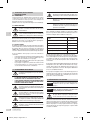
Never submerge the end of the wire or any
wire couplings in water.
Support the wire by attaching it to the delivery
pipe.
8.2.HANDLING
Avoid exposing the wire to direct sunlight or
twisting it to prevent overheating.
Before handling pumps, make sure they are
disconnected from power supplies.
Move the pumps using the specific handle or eye
bolts. Do not, UNDER ANY CIRCUMSTANCES,
lift by the electric wires.
Depending on their weight, pumps may be moved manually
or by using specific equipment. In any case, the specific
handle must be used.
8.3.INSTALLATION
Use a mega-ohm meter to measure the insulation resistance
between the earth wire and phases. If insulation resistance
in the respective sections is less than 500MΩ, check the
pump. During measurement, keep the section connecting
up to the electrical power supply away from the earth.
In installing the pump, following these instructions:
- the pump can operate in any position;
- the tubes must be supported and aligned in order to
avoid creating demands on the pump;
- do not use too many bends (goosenecks) and valves
in the system;
- pumps do not have a control system against dry
functioning; consider this in the event of unmanned
operation.
9.WIRING
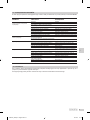
Refer to paragraph 7.2 for wiring data.
-
-
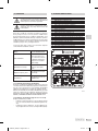
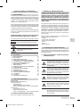
INSTALLATION MUST BE CARRIED OUT BY A
QUALIFIED TECHNICIAN.
WE RECOMMEND A HIGHLY SENSITIVE CIRCUIT
BREAKER IS INSTALLED IN THE ELECTRICAL
SYSTEM.
The motor-driven pump must be powered by
the electrical panel that includes a switch, fuse
and circuit breaker calibrated to the motordriven pump’s absorbed current.
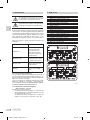
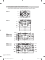
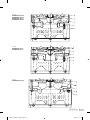
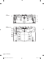
With reference to the table concerning wire colour (Fig.
15.2.1), prepare the wiring according to the indications
given in the table below:
Pump
Wiring diagram
DUMPER 10 51-S M
Fig. 15.2.4
DUMPER 51 58-S
Fig. 15.2.5
Single-phase pumps
Fig. 15.2.2
Three-phase pumps up to 7.5 kW (DOL)
Fig. 15.2.6
Three-phase pumps as from 12 kW (Y/Δ)
Fig. 15.2.3
Immerse the pump and start it up.
In the event of three-phase pumps, check the direction of
rotation if current exceeds plate data, flow is reduced and
the pump will emit an unusual noise. If necessary, invert
two phases on the control panel.
Very long power leads may cause the differential switch to
intervene early, particularly during pump start-up. To avoid
this problem, install a less sensitive differential switch.
Should the pump be fitted with thermal probe inserted
within the motor, connect the conductors from it to the
control panel in order to protect against overheating.
10.START-UP AND USE
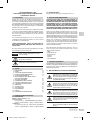
WARNING!
Do not operate the pump in conditions other
than those described in chap. 7.
WARNING!
Do not operate the pump without water for
more than 30 minutes.
The power mains must have an efficient earthing
system according to the electrical standards
in force in your country: this is the installer’s
responsibility.
Do not use the pump if people or animals are
in contact with the water.
To prevent potential shock in the event of faults,
install a circuit breaker to be exclusively used
for the pump.
Carry out all connections, turn the pump on and off a
couple of times with the delivery valve (if present) slightly
open to check the system.
Turn the pump on and gradually open the delivery valve (if
present) until the desired flow has been reached.
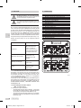
Do not connect the yellow-green wire to the
power mains: it should only be connected to
the earthing system.
GB
9
Istruzioni_Dumper - 6 lingue.indd 9
19/10/11 11.16