1
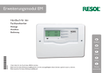
SV6 Sensorverteiler Handbuch für den Fachhandwerker Montage Anschluss de 11208608 *11208608* Handbuch en Manual fr Vielen Dank für den Kauf dieses RESOL-Gerätes. Bitte lesen Sie diese Anleitung sorgfältig durch, um die Leistungsfähigkeit dieses Gerätes optimal nutzen zu können. Bitte bewahren Sie diese Anleitung sorgfältig auf. Manuel www.resol.de Sicherheitshinweise • WARNUNG bedeutet, dass Personenschäden, unter Umständen auch lebensgefährliche Verletzungen auftreten können Bitte beachten Sie diese Sicherheitshinweise genau, um Gefahren und Schäden für Menschen und Sachwerte auszuschließen. • ACHTUNG bedeutet, dass Sachschäden auftreten können Vorschriften Beachten Sie bei Arbeiten die jeweiligen, gültigen Normen, Vorschriften und Richtlinien! Hinweis Hinweise sind mit einem Informationssymbol gekennzeichnet. Zielgruppe ÎÎ Textabschnitte, die mit einem Pfeil gekennzeichnet sind, fordern zu einer Handlung auf. Diese Anleitung richtet sich ausschließlich an autorisierte Fachkräfte. Elektroarbeiten dürfen nur von Elektrofachkräften durchgeführt werden. Entsorgung • Verpackungsmaterial des Gerätes umweltgerecht entsorgen. • Altgeräte müssen durch eine autorisierte Stelle umweltgerecht entsorgt werden. Bestimmungsgemäße Verwendung Auf Wunsch nehmen wir Ihre bei uns gekauften Altgeräte zurück und garantieren für eine umweltgerechte Entsorgung. Der Sensorverteiler ist für die Verstärkung und Ausgabe eines Sensorsignals unter Berücksichtigung der in dieser Anleitung angegebenen technischen Daten bestimmt. Irrtum und technische Änderungen vorbehalten. Die bestimmungswidrige Verwendung führt zum Ausschluss jeglicher Haftungsansprüche. Angaben zum Gerät CE-Konformitätserklärung Das Produkt entspricht den relevanten Richtlinien und ist daher mit der CE-Kennzeichnung versehen. Die Konformitätserklärung kann beim Hersteller angefordert werden. Hinweis Starke elektromagnetische Felder können die Funktion des Geräts beeinträchtigen. ÎÎ Sicherstellen, dass Gerät und Anlage keinen starken elektromagnetischen Strahlungsquellen ausgesetzt sind. Symbolerklärung WARNUNG! Warnhinweise sind mit einem Warndreieck gekennzeichnet! ÎÎEs wird angegeben, wie die Gefahr vermieden werden kann! Signalwörter kennzeichnen die Schwere der Gefahr, die auftritt, wenn sie nicht vermieden wird. © 20150313_11208608_SV6.mon5s.indd 2 Inhalt 1 2 2.1 2.2 2.3 2.4 2.5 2.6 3 4 Übersicht............................................................................................... 3 Installation............................................................................................ 4 Montage...........................................................................................................................4 Elektrischer Anschluss..................................................................................................5 Datenkommunikation / Bus..........................................................................................5 Anschlussbeispiel...........................................................................................................6 Betriebskontroll-LED...................................................................................................6 Anwendungsbeispiel.....................................................................................................6 Fehlersuche........................................................................................... 6 Zubehör................................................................................................. 7 1 Technische Daten Übersicht Kabeldurchführungen mit Zugentlastungsbügeln de Mit dem RESOL SV6 wird das Signal eines Pt1000-Temperatursensors verteilt und Eingänge: 1 Temperatursensor Pt1000 an 6 Ausgängen ausgegeben. Somit kann das Signal eines einzigen Sensors bis zu 6 Ausgänge: 6 Temperatursensoren Pt1000 Reglern zu Verfügung gestellt werden. Im Fall eines Sensorfehlers blinkt die LED rot. Versorgung: 100 … 240 V~ (50 … 60 Hz) Anschlussart: Y • Verteilt das Signal eines Pt1000-Temperatursensors Leistungsaufnahme: < 1 W • Einen Sensor für mehrere Regler nutzen • Verstärkt das Signal zur Messwertübermittlung über große Leitungs- Bemessungsstoßspannung: 2,5 V Datenschnittstelle: RESOL VBus® längen Funktionen: Verstärkung des Sensorsignals und Ausgabe an 6 Ausgängen Gehäuse: Kunststoff, PC-ABS und PMMA Montage: Wandmontage, Schalttafel-Einbau möglich Gehäusedeckel KreuzschlitzAnzeige / Display: Kontroll-LED schraube Schutzart: IP 20 / DIN EN 60529 Schutzklasse: II Umgebungstemperatur: 0 … 40 °C Verschmutzungsgrad: 2 Maße: 144 x 208 x 43 mm Sicherung / Ersatzsicherung 144 100 16.75 16.75 Aufhängung 144 100 180 180 180 208 180 208 144 43.3 12.5 180 12.5 100 43.3 16.75 Befestigung 3 2 Installation 2.1 Montage WARNUNG! Elektrischer Schlag! 1 Bei geöffnetem Gehäuse liegen stromführende Bauteile frei! ÎÎVor jedem Öffnen des Gehäuses das Gerät allpolig von der Netzspannung trennen! 2 0 Auto I Hinweis Starke elektromagnetische Felder können die Funktion des Gerätes beeinträchtigen. ÎÎ Sicherstellen, dass Gerät und System keinen starken elektromagnetischen Strahlungsquellen ausgesetzt sind. de Das Gerät ausschließlich in trockenen Innenräumen montieren. Für eine einwandfreie Funktion an dem ausgewählten Ort das Gerät keinen starken elektromagnetischen Feldern aussetzten. Das Gerät muss über eine zusätzliche Einrichtung mit einer Trennstrecke von mindestens 3 mm allpolig bzw. mittels einer Trennvorrichtung (Sicherung) nach den geltenden Installationsregeln vom Netz getrennt werden können. Bei der Installation der Netzanschlussleitung und der Sensorleitungen auf getrennte Verlegung achten. ÎÎ Kreuzschlitzschrauben in dem Gehäusedeckel herausdrehen und Gehäusedeckel abnehmen. ÎÎ Aufhängung auf dem Untergrund markieren und beiliegenden Dübel mit zugehöriger Schraube vormontieren. ÎÎ Gehäuse am Aufhängungspunkt einhängen und Befestigungslöcher auf dem Untergrund markieren (Lochabstand 180 mm). ÎÎ Löcher bohren und anschließend untere Dübel einsetzen. ÎÎ Gehäuse oben einhängen und mit unteren Befestigungsschrauben fixieren. ÎÎ Elektrische Anschlüsse gemäß Klemmenbelegung vornehmen (siehe Seite 6). ÎÎ Gehäusedeckel auf das Gehäuse aufsetzen. ÎÎ Gehäuse mit den Befestigungsschrauben verschließen. 4 3 4 180mm 5 6 0 Auto I Elektrischer Anschluss siehe Seite 5 Elektrischer Anschluss Den Außentemperatursensor mit beliebiger Polung an die Klemme S in anschließen. WARNUNG! Elektrischer Schlag! Die Regler an die Ausgänge S1 bis S6 unter Beachtung der Polung anschließen: S1 out = Regler 1 S2 out = Regler 2 S3 out = Regler 3 S4 out = Regler 4 S5 out = Regler 5 S6 out = Regler 6 Bei geöffnetem Gehäuse liegen stromführende Bauteile frei! ÎÎ Vor jedem Öffnen des Gehäuses das Gerät allpolig von der Netzspannung trennen! ACHTUNG! Elektrostatische Entladung! Elektrostatische Entladung kann zur Schädigung elektronischer Bauteile führen! ÎÎ Vor dem Berühren des Gehäuseinneren für Entladung sorgen. Dazu ein geerdetes Bauteil (z. B. Wasserhahn, Heizkörper o. ä.) berühren. Die Netzleitung an den folgenden Klemmen anschließen: 18 = Neutralleiter N 19 = Leiter L 17 = Erdungsklemme ⌯ Hinweis Der Anschluss des Gerätes an die Netzspannung ist immer der letzte Ar2.3 Datenkommunikation / Bus beitsschritt! Das Gerät verfügt über den RESOL VBus® zur Datenkommunikation. Der Anschluss Hinweis erfolgt mit beliebiger Polung an den mit VBus gekennzeichneten Klemmen. Über Das Gerät muss jederzeit vom Netz getrennt werden können. diesen Datenbus kann ein RESOL-Alarmmodul angeschlossen werden. ÎÎ Den Netzstecker so anbringen, dass er jederzeit zugänglich ist. ÎÎ Ist dies nicht möglich, einen jederzeit zugänglichen Schalter installieren. Das Gerät nicht in Betrieb nehmen, wenn sichtbare Beschädigungen bestehen! Die Stromversorgung des Gerätes erfolgt über eine Netzleitung. Die Versorgungsspannung muss 100 … 240 V~ (50 … 60 Hz) betragen. Flexible Leitungen mit den beiliegenden Zugentlastungsbügeln und den zugehörigen Schrauben am Gehäuse fixieren. S1 out SV6 Made in Germany S2 S3 out out 1 2 3 T0,2A 100 ... 240 V~ 50-60 Hz IP 20 S4 out 4 Sensorklemmen S5 out 5 S6 out 6 S in VBus N VBus - Klemmen L Netzanschlussklemmen 5 de 2.2 3 Anschlussbeispiel S1 out 1 2 T0,2A 100 ... 240 V~ IP 20 SV6 Made in Germany S2 S3 out out S4 out 3 4 S5 out S6 out 5 S in 6 50-60 Hz Betriebskontroll-LED blinkt rot VBus T4A 100 ... 240V 50-60 Hz SD 3 4 5 6 7 8 FAP13 2.5 VBus AM1 Betriebskontroll-LED de Anwendungsbeispiel Außentemperatursensor Sensorverteiler SV6 N R2 R1 L Bei erloschener Betriebskontroll-LED die Stromversorgung des Gerätes kontrollieren. Ist diese unterbrochen? N N N nein Das Gerät ist mit einer Sicherung geschützt. Nach Abnahme des Gehäusedeckels wird der Sicherungshalter zugänglich, der auch die Ersatzsicherung enthält. Zum Austausch der Sicherung den Sicherungshalter nach vorne aus dem Sockel ziehen. Grün: Alles in Ordnung Rot blinkend: Sensorfehler 2.6 Betriebskontroll-LED dauerhaft erloschen N R3 11 L S7 9 10 R2 R3 R4 R4 R1-R3|1 (1) A 240V~ S6 VBus S5/V40 PWM A 0-10V PWM B 0-10V S3 S4 S1 S2 2 DeltaTherm® HC mini Sicherung 6 L DeltaSol® SL Made in Germany R4|1 (1) A 30V GND 1 N Sensordefekt. Sensor prüfen. IP 20 Sensors Fehlersuche R1 2.4 ja Ursache überprüfen und Stromversorgung wiederherstellen. 4 Zubehör Alarmmodul AM1 de Das Alarmmodul AM1 dient der Signalisierung von Anlagenfehlern. Es wird an den VBus® des Reglers angeschlossen und gibt über eine rote LED ein optisches Signal aus, wenn ein Fehler auftritt. Darüber hinaus verfügt das AM1 über einen Relaisausgang, der die Aufschaltung auf eine Gebäudeleittechnik ermöglicht. Somit kann im Fehlerfall eine Sammelstörmeldung ausgegeben werden. So werden Ertragsstabilität und Betriebssicherheit der Anlage optimal gewährleistet. 7 Ihr Fachhändler: RESOL – Elektronische Regelungen GmbH Heiskampstraße 10 45527 Hattingen / Germany Tel.: +49 (0) 23 24 / 96 48 - 0 Fax: +49 (0) 23 24 / 96 48 - 755 www.resol.de [email protected] Wichtiger Hinweis Die Texte und Zeichnungen dieser Anleitung entstanden mit größtmöglicher Sorgfalt und nach bestem Wissen. Da Fehler nie auszuschließen sind, möchten wir auf folgendes hinweisen: Grundlage Ihrer Projekte sollten ausschließlich eigene Berechnungen und Planungen an Hand der jeweiligen gültigen Normen und Vorschriften sein. Wir schließen jegliche Gewähr für die Vollständigkeit aller in dieser Anleitung veröffentlichten Zeichnungen und Texte aus, sie haben lediglich Beispielcharakter. Werden darin vermittelte Inhalte benutzt oder angewendet, so geschieht dies ausdrücklich auf das eigene Risiko des jeweiligen Anwenders. Eine Haftung des Herausgebers für unsachgemäße, unvollständige oder falsche Angaben und alle daraus eventuell entstehenden Schäden wird grundsätzlich ausgeschlossen. Anmerkungen Das Design und die Spezifikationen können ohne Vorankündigung geändert werden. Die Abbildungen können sich geringfügig vom Produktionsmodell unterscheiden. Impressum Diese Montage- und Bedienungsanleitung einschließlich aller seiner Teile ist urheberrechtlich geschützt. Eine Verwendung außerhalb des Urheberrechts bedarf der Zustimmung der Firma RESOL – Elektronische Regelungen GmbH. Dies gilt insbesondere für Vervielfältigungen / Kopien, Übersetzungen, Mikroverfilmungen und die Einspeicherung in elektronischen Systemen. © RESOL – Elektronische Regelungen GmbH SV6 Sensor distribution box Manual for the specialised craftsman Mounting Connection en Thank you for buying this RESOL product. Please read this manual carefully to get the best performance from this unit. Please keep this manual safe. Manual www.resol.com Safety advice • WARNING means that injury, possibly life-threatening injury, can occur. Please pay attention to the following safety advice in order to avoid danger and damage to people and property. • ATTENTION means that damage to the appliance can occur. Note Notes are indicated with an information symbol. Instructions Attention must be paid to the valid local standards, regulations and directives! Target group These instructions are exclusively addressed to authorised skilled personnel. Only qualified electricians should carry out electrical works. Information about the product Proper usage The sensor distribution box is designed for amplifying and distributing a sensor signal in compliance with the technical data specified in this manual. Improper use excludes all liability claims. ÎÎ Arrows indicate instruction steps that should be carried out. Disposal • Dispose of the packaging in an environmentally sound manner. • Dispose of old appliances in an environmentally sound manner. On request we will take back your old appliances bought from us and guarantee an environmentally sound disposal of the devices. Subject to technical change. Errors excepted. en CE Declaration of conformity The product complies with the relevant directives and is therefore labelled with the CE mark. The Declaration of Conformity is available on request, please contact the manufacturer. Note Strong electromagnetic fields can impair the function of the device. ÎÎ Make sure the device as well as the system are not exposed to strong electromagnetic fields. Description of symbols WARNING! Warnings are indicated with a warning triangle! ÎÎThey contain information on how to avoid the danger described. Signal words describe the danger that may occur, when it is not avoided. © 20150313_11208608_SV6.mon5s.indd 10 Contents 1 2 2.1 2.2 2.3 2.5 2.6 3 2.4 4 Overview............................................................................................. 11 Installation.......................................................................................... 12 Mounting...................................................................................................................... 12 Electrical connection................................................................................................. 13 Data communication / Bus....................................................................................... 13 Operating control LED............................................................................................. 14 Application example.................................................................................................. 14 Troubleshooting.................................................................................. 14 Connection example................................................................................................. 14 Accessories......................................................................................... 15 Technical data Overview With the RESOL SV6, the signal of a Pt1000 temperature sensor can be distributed to 6 outputs. Thus, the signal of a single sensor can be made available to up to 6 controllers. In the case of a sensor fault, the LED will flash red. • Distributes the signal of a Pt1000 temperature sensor • Enables using a single sensor for multiple controllers • Amplifies the signal for transmitting values over great cable lengths Cover Crosshead screw Cable conduits with strain relief Inputs: 1 Pt1000 temperature sensor Outputs: 6 Pt1000 temperature sensors Power supply: 100 … 240 V~ (50 … 60 Hz) Supply connection: type Y attachment Power consumption < 1 W Rated impulse voltage: 2.5 V Data interface: RESOL VBus® Functions: amplifying and distributing a sensor signal to 6 outputs Housing: plastic, PC-ABS and PMMA Mounting: wall mounting, also suitable for mounting into patch panels Indication / Display: control LED Protection type: IP 20 / DIN EN 60529 Protection class: II Ambient temperature: 0 … 40 °C Degree of pollution: 2 Dimensions: 144 x 208 x 43 mm en 1 Fuse / spare fuse 144 100 16.75 16.75 Upper fastening 144 100 180 180 180 208 180 208 144 43.3 12.5 180 12.5 100 43.3 16.75 Lower fastening 11 2 Installation 2.1 Mounting WARNING! Electric shock! Upon opening the housing, live parts are exposed! ÎÎAlways disconnect the device from power supply before opening the housing! 1 2 0 Auto I Note Strong electromagnetic fields can impair the function of the device. ÎÎ Make sure the device as well as the system are not exposed to strong electromagnetic fields. en The device must only be located in dry interior rooms. It is not suitable for installation in hazardous locations and should be protected against electromagnetic fields. The device must additionally be supplied from a double pole switch with contact gap of at least 3 mm. Please pay attention to separate routing of sensor cables and mains cables. ÎÎ Unscrew the crosshead screw from the cover and remove the cover. ÎÎ Mark the upper fastening point on the wall. Drill and fasten the enclosed wall plug and screw leaving the head protruding. ÎÎ Hang the housing from the upper fastening point and mark the lower fastening points (centres 180 mm). ÎÎ Drill and insert the lower wall plugs. ÎÎ Fasten the housing to the wall with the lower fastening screws and tighten. ÎÎ Carry out the electrical wiring in accordance with the terminal allocation (see page 6). ÎÎ Put the cover on the housing. ÎÎ Attach with the fastening screws. 3 4 180mm 5 0 Auto I Electrical connection see page 13 12 6 Electrical connection Connect the outdoor temperature sensor to the terminal S in (either polarity). Electric shock! Upon opening the housing, live parts are exposed! ÎÎAlways disconnect the device from power supply before opening the housing! WARNING! ATTENTION! ESD damage! Electrostatic discharge can lead to damage to electronic components! ÎÎ Take care to discharge properly before touching the inside of the device! To do so, touch a grounded surface such as a radiator or tap! Note Connecting the device to the power supply must always be the last step of the installation! Note It must be possible to disconnect the device from the mains at any time. ÎÎ Install the mains plug such that it is accessible at any time. ÎÎ If this is not possible, install a switch that can be accessed. Connect the controller to the outputs S1 to S6 with correct polarity: S1 out = controller 1 S2 out = controller 2 S3 out = controller 3 S4 out = controller 4 S5 out = controller 5 S6 out = controller 6 Connect the mains cable to the following terminals: 18 = neutral conductor N 19 = conductor L 17 = grounding terminal ⌯ 2.3 Data communication / Bus The device is equipped with a RESOL VBus® for data communication. The connection is to be carried out at the terminals marked VBus (any polarity).This data bus can be used for connecting a RESOL Alarm Module to the SV6. Do not use the device if it is visibly damaged! The device is supplied with power via a mains cable.The power supply of the device must be 100 … 240 V~ (50 … 60 Hz). Attach flexible cables to the housing with the enclosed strain relief and the corresponding screws. S1 out SV6 Made in Germany S2 S3 out out 1 2 3 T0,2A 100 ... 240 V~ 50-60 Hz IP 20 S4 out 4 Sensor terminals S5 out 5 S6 out 6 S in VBus N VBus® terminals L Mains terminals 13 en 2.2 Connection example 2 S4 out 3 4 S5 out T0,2A S6 out 5 S in 6 VBus T4A 100 ... 240V 50-60 Sensor Hz SD 1 2 3 4 5 R4 6 7 8 FAP13 2.5 R2 R3 R3 11 Operating control LED permanently off. L R1 L N 9 10 L S7 AM1 N R2 N If the operating control LED is off, check the power supply of the device. Is it disconnected? N no N en The device is protected by a fuse. The fuse holder (which also holds the spare fuse) becomes accessible when the cover is removed. To replace the fuse, pull the fuse holder from the base. Operating control LED Green: Red flashing: 2.6 R1-R3|1 (1) A 240V~ S6 VBus R4 GND N fault. Check sensor. DeltaSol® SL Made in Germany R4|1 (1) A 30V VBus S5/V40 S3 S4 S2 S1 PWM A 0-10V PWM B 0-10V IP 20 Sensors Troubleshooting 100 ... 240 V~ Operating control LED flashes red. 50-60 Hz IP 20 SV6 Made in Germany S1 S2 S3 out out out 1 3 R1 2.4 Everything OK Sensor fault Application example Outdoor temperature sensor SV6 Sensor distribution box DeltaTherm® HC mini fuse 14 yes Check the supply line and reconnect it. 4 Accessories AM1 Alarm Module en The AM1 Alarm Module is designed to signal system failures. It is to be connected to the VBus® of the controller and issues an optical signal via the red LED if a failure has occurred. The AM1 also has a relay output, which can e. g. be connected to a building management system (BMS). Thus, a collective error message can be issued in the case of a system failure. Thus, the reliability and the stable yield of the system are ensured. 15 Distributed by: RESOL – Elektronische Regelungen GmbH Heiskampstraße 10 45527 Hattingen / Germany Tel.: +49 (0) 23 24 / 96 48 - 0 Fax: +49 (0) 23 24 / 96 48 - 755 www.resol.com [email protected] Important note The texts and drawings in this manual are correct to the best of our knowledge. As faults can never be excluded, please note: Your own calculations and plans, under consideration of the current standards and directions should only be basis for your projects. We do not offer a guarantee for the completeness of the drawings and texts of this manual - they only represent some examples. They can only be used at your own risk. No liability is assumed for incorrect, incomplete or false information and / or the resulting damages. Note The design and the specifications can be changed without notice. The illustrations may differ from the original product. Imprint This mounting- and operation manual including all parts is copyrighted. Another use outside the copyright requires the approval of RESOL – Elektronische Regelungen GmbH. This especially applies for copies, translations, micro films and the storage into electronic systems. © RESOL – Elektronische Regelungen GmbH SV6 Répartiteur de sonde Manuel pour le technicien habilité Montage Raccordement fr Merci d'avoir acheté ce produit RESOL. Veuillez lire le présent mode d’emploi attentivement afin de pouvoir utiliser l’appareil de manière optimale.Veuillez conserver ce mode d’emploi. Manuel www.resol.fr Recommandations de sécurité Veuillez lire attentivement les recommandations de sécurité suivantes afin d’éviter tout dommage aux personnes et aux biens. Instructions Lors des travaux, veuillez respecter les normes, réglementations et directives en vigueur ! Groupe cible Ce manuel d‘instructions vise exclusivement les techniciens habilités. Toute opération électrotechnique doit être effectuée par un technicien en électrotechnique. Informations concernant l’appareil Utilisation conforme fr Le répartiteur de sonde est conçu pour démultiplier le signal d'une sonde en tenant compte des données techniques énoncées dans le présent manuel. Toute utilisation non conforme entraînera une exclusion de la garantie. Déclaration de conformité CE Les avertissements caractérisent la gravité du danger qui survient si celui-ci n’est pas évité. • AVERTISSEMENT indique que de graves dommages corporels, voir même un danger de mort, peuvent survenir • ATTENTION indique que des dommages aux biens peuvent survenir Note Toute information importante communiquée à l‘utilisateur est précédée de ce symbole. ÎÎ Les instructions sont précédées d‘une flèche. Traitement des déchets • Veuillez recycler l‘emballage de l‘appareil. • Les appareils en fin de vie doivent être déposés auprès d‘une déchèterie ou d‘une collecte spéciale de déchets d‘équipements électriques et électroniques. Sur demande, nous reprenons les appareils usagés que vous avez achetés chez nous en garantissant une élimination respectueuse de l’environnement. Sous réserve d’erreurs et de modifications techniques. Le marquage „CE“ est apposé sur le produit, celui-ci étant conforme aux dispositions communautaires prévoyant son apposition. La déclaration de conformité est disponible auprès du fabricant sur demande. Note Des champs électromagnétiques trop élevés peuvent perturber le fonctionnement de l‘appareil. ÎÎ Veillez à ne pas exposer ce dernier ni le système à des champs électromagnétiques trop élevés. Explication des symboles AVERTISSEMENT ! Les avertissements de sécurité sont précédés d’un triangle de signalisation ! ÎÎ Ils indiquent comment éviter le danger ! © 20150313_11208608_SV6.mon5s.indd 18 Contenu 1 2 2.1 2.2 2.3 2.4 3 4 Vue d'ensemble................................................................................... 19 Installation.......................................................................................... 20 Montage........................................................................................................................ 20 Raccordement électrique......................................................................................... 21 Transmission de données / Bus............................................................................... 21 Exemple de branchement......................................................................................... 22 Détection de pannes.......................................................................... 22 Accessoires.......................................................................................... 23 Caractéristiques techniques Vue d'ensemble Le RESOL SV6 démultiplie le signal d'une sonde de température Pt1000 sur 6 sorties. Le signal d'une seule sonde est mis à disposition de jusqu'à 6 régulateurs. En cas de panne de la sonde, le témoin lumineux LED clignote en rouge. • Démultiplie le signal d'une sonde de température Pt1000 • Utilisation d'une seule sonde pour plusieurs régulateurs • Augmente l'intensité du signal pour le transmettre sur de grandes longueurs de câble Couvercle Vis cruciforme Passes câbles avec serre-fils Entrées : 1 sonde de température Pt1000 Sorties : 6 sondes de température Pt1000 Alimentation : 100 … 240 V~ (50 … 60 Hz) Type de connexion : Y Puissance absorbée : < 1 W Tension de choc : 2,5 V Interface de données : RESOL VBus® Fonctions : démultiplication du signal d'une sonde sur 6 sorties Boîtier : en plastique, PC-ABS et PMMA Montage : mural ou dans un panneau de commande Affichage / écran : témoin de contrôle LED Type de protection : IP 20 / DIN EN 60529 Classe de protection : II Température ambiante : 0 … 40 °C Degré de pollution : 2 Dimensions : 144 x 208 x 43 mm fr 1 Fusible / fusible de rechange 144 100 16.75 16.75 Oeillet de suspension 144 100 180 180 180 208 180 208 144 43.3 12.5 180 12.5 100 43.3 16.75 Attaches 19 2 Installation 2.1 Montage AVERTISSEMENT ! Choc électrique ! Lorsque le boîtier est ouvert, des composants sous tension sont accessibles ! ÎÎDébranchez l'appareil du réseau électrique avant de l'ouvrir ! Note Des champs électromagnétiques trop élevés peuvent perturber le fonctionnement de l‘appareil. ÎÎ Veillez à ne pas exposer ce dernier ni le système à des champs électromagnétiques trop élevés. 1 0 Auto I 3 fr Réalisez le montage de l’appareil dans une pièce intérieure sèche. L'appareil doit pouvoir être séparé du réseau électrique par le biais d'un dispositif supplémentaire (avec une distance minimum de séparation de 3 mm sur tous les pôles) ou par le biais d’un dispositif de séparation (fusible), conformément aux règles d’installation en vigueur. Lors de l’installation, veillez à maintenir le câble de connexion au réseau électrique séparé des câbles des sondes. ÎÎ Dévissez les vis cruciformes du couvercle et détachez celui-ci du boîtier. ÎÎ Marquez un point d’accrochage sur le mur, percez un trou et introduisez-y la cheville et la vis correspondante (fournies avec le matériel de montage). ÎÎ Accrochez le boîtier de l’appareil sur la vis de fixation. Marquez les points de fixation inférieurs et percez les trous correspondants (la distance entre les deux trous doit être égale à 180 mm). ÎÎ Introduisez y les chevilles. ÎÎ Accrochez l’appareil à la vis supérieure et fixez-le au mur avec la vis inférieure. ÎÎ Effectuez toutes les connexions électriques selon le plan de connexion des sondes (cf page 6). ÎÎ Replacez le couvercle sur le boîtier. ÎÎ Vissez le boîtier avec les vis correspondantes. 20 2 4 180mm 5 6 0 Auto I Branchement électrique voir page 5 Raccordement électrique Branchez la sonde de température extérieure sur la borne S in en tenant compte de la polarité. AVERTISSEMENT ! Choc électrique ! Lorsque le boîtier est ouvert, des composants sous tension sont accessibles ! ÎÎ Débranchez l'appareil du réseau électrique avant de l'ouvrir ! Décharges électrostatiques ! Des décharges électrostatiques peuvent endommager les composants électroniques de l'appareil ! ÎÎ Éliminez l’électricité statique que vous avez sur vous avant de manipuler les parties internes de l’appareil.Touchez pour cela, un appareil mis à la terre tel qu’un robinet ou un radiateur. ATTENTION ! Note Le raccordement au réseau doit toujours se faire en dernier ! Note Il est nécessaire de pouvoir débrancher l’appareil du réseau électrique à tout moment. ÎÎ Installez la prise d'alimentation électrique de façon qu’elle soit accessible à tout moment. ÎÎ Si cela n’est pas possible, installez un interrupteur accessible. Branchez les régulateurs sur les sorties S1 à S6 en tenant compte de la polarité: S1 out = régulateur 1 S2 out = régulateur 2 S3 out = régulateur 3 S4 out = régulateur 4 S5 out = régulateur 5 S6 out = régulateur 6 Branchez le câble secteur sur les bornes suivatnes : 18 = Conducteur neutre N 19 = Conducteur L 17 = Bornes de mise à la terre ⌯ 2.3 Transmission de données / Bus L'appareil est doté du RESOL VBus® lui permettant de communiquer avec des modules externes. Le bus se branche sur les bornes VBus (pôles interchangeables). Ce bus de données permet de brancher le module d'alarme RESOL sur le SV6. N’utilisez pas l’appareil en cas d’endommagement visible ! L’alimentation électrique de l'appareil s’effectue à travers un câble secteur. La tension d’alimentation doit être comprise entre 100 et 240 V~ (50 et 60 Hz). Fixez les câbles sur le boîtier à l’aide des serre-fils inclus dans le matériel de montage et des vis correspondantes. S1 out SV6 Made in Germany S2 S3 out out 1 2 3 T0,2A 100 ... 240 V~ 50-60 Hz IP 20 S4 out 4 Bornes pour sondes S5 out 5 S6 out 6 S in VBus N Bornes VBus L Bornes pour raccordement au réseau 21 fr 2.2 3 Exemple de branchement S1 out 1 2 S4 out 3 4 S5 out T0,2A 50-60 Hz S6 out 5 S in 6 VBus T4A 100 ... 240V 50-60 Sonde Hz SD 2 3 4 5 R4 6 7 8 FAP13 4.1 R3 AM1 fr Exemple d'application Sonde de température extérieure Répartiteur de sonde SV6 N R2 R1 L N Vérifiez l’alimentation électrique de l'appareil. Est-elle interrompue? N non N L’appareil est protégé par un fusible. Pour accéder au porte-fusible, retirez le couvercle. Le porte-fusible contient également le fusible de rechange. Pour changer le fusible, détachez le porte-fusible en le tirant vers l’avant. Témoin lumineux de contrôle Vert : Fonctionnement normal Rouge clignotant : Erreur sonde 4.2 Témoin lumineux de contrôle LED éteint en permanence L N R3 11 DeltaTherm® HC mini Fusible 22 L S7 9 10 R2 R1-R3|1 (1) A 240V~ S6 VBus R4 GND 1 N défectueuse.Vérifiez la sonde. DeltaSol® SL Made in Germany R4|1 (1) A 30V VBus S5/V40 S3 S4 S2 S1 PWM A 0-10V PWM B 0-10V IP 20 Sensors Détection de pannes 100 ... 240 V~ Témoin lumineux de contrôle LED clignote en rouge IP 20 SV6 Made in Germany S2 S3 out out R1 2.4 oui Cherchez la cause du problème et rétablissez le courant. 4 Accessoires Module avertisseur AM1 fr Le module avertisseur AM1 sert à signaler toute erreur produite dans l'installation. Il se branche sur le VBus® du régulateur et délivre un signal optique d’alarme à travers une LED rouge en cas de panne. En outre, le module AM1 est doté d'une sortie relais permettant le branchement sur un système de gestion technique du bâtiment. Par conséquent, l’AM1 peut émettre un message d’erreur centralisé en cas de panne. Cela garantit un rendement stable et une meilleure sécurité de fonctionnement de l‘installation. 23 Votre distributeur: RESOL – Elektronische Regelungen GmbH Heiskampstraße 10 45527 Hattingen / Germany Tel.: +49 (0) 23 24 / 96 48 - 0 Fax: +49 (0) 23 24 / 96 48 - 755 www.resol.fr [email protected] Note importante : Les textes et les illustrations de ce manuel ont été réalisés avec le plus grand soin et les meilleures connaissances possibles. Étant donné qu’il est, cependant, impossible d’exclure toute erreur, veuillez prendre en considération ce qui suit : Vos projets doivent se fonder exclusivement sur vos propres calculs et plans, conformément aux normes et directives valables. Nous ne garantissons pas l’intégralité des textes et des dessins de ce manuel; ceux-ci n’ont qu’un caractère exemplaire. L’utilisation de données du manuel se fera à risque personnel. L’éditeur exclue toute responsabilité pour données incorrectes, incomplètes ou érronées ainsi que pour tout dommage en découlant. Note : Le design et les caractéristiques du régulateur sont susceptibles d’être modifiés sans préavis. Les images sont susceptibles de différer légèrement du modèle produit. Achevé d’imprimer Ce manuel d’instructions pour le montage et l’utilisation de l’appareil est protégé par des droits d’auteur, toute annexe inclue. Toute utilisation en dehors de ces mêmes droits d’auteur requiert l’autorisation de la société RESOL – Elektronische Regelungen GmbH. Ceci s’applique en particulier à toute reproduction / copie, traduction, microfilm et à tout enregistrement dans un système électronique. © RESOL – Elektronische Regelungen GmbH