1
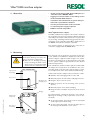
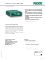
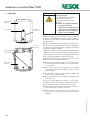
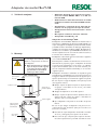
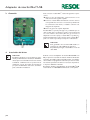
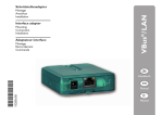
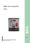
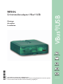
Montage Anschluss ® Installation VBus /USB RESOL Schnittstellenadapter VBus®/USB D Anleitung en Manual 48005220 *48005220* Manual Manuale Manual Vielen Dank für den Kauf dieses RESOL-Gerätes. Bitte lesen Sie diese Anleitung sorgfältig durch, um die Leistungsfähigkeit dieses Gerätes optimal nutzen zu können. Bitte bewahren Sie diese Anleitung sorgfältig auf. www.resol.de Schnittstellenadapter VBus®/USB Inhaltsverzeichnis Sicherheitshinweise.................................................. 2 Symbolerklärung...................................................... 2 Angaben zum Gerät................................................. 2 Technische Daten .................................................... 2 Sicherheitshinweise Bitte beachten Sie diese Sicherheitshinweise genau, um Gefahren und Schäden für Menschen und Sachwerte auszuschließen. Vorschriften Beachten Sie bei allen Arbeiten die nationalen und regionalen gesetzlichen Vorschriften, Normen, Richtlinien und Sicherheitsbestimmungen. 1. Übersicht............................................................... 3 2.Montage................................................................. 3 3.Anschluss............................................................... 4 4.Treiberinstallation................................................ 4 Irrtum und technische Änderungen vorbehalten Symbolerklärung Warnhinweise sind mit einem Warndreieck gekennzeichnet! ÎÎ Es wird angegeben, wie die Gefahr vermieden werden kann! Signalwörter kennzeichnen die Schwere der Gefahr, die auftritt, wenn sie nicht vermieden wird. Warnung bedeutet, dass schwere Personenschäden oder sogar Lebengefahr auftreten können Achtung bedeutet, dass Sachschäden auftreten können Hinweis Hinweise sind mit einem Informationssymbol gekennzeichnet. Lieferumfang 1 × Schnittstellenadapter VBus®/USB 1 × CD-ROM mit Treiber und der RSC Software 1 × Adapterleitung USB – Mini-USB 1 × VBus®-Anschlussleitung 1 × Zubehörbeutel mit: 2 × Schraube und Dübel 4 × selbstklebende Gummifüßchen ÎÎ Textabschnitte, die mit einem Pfeil gekennzeichnet sind, fordern zu einer Handlung auf. Systemvoraussetzungen •• freie USB-Schnittstelle zum Anschluss des Adapters •• Microsoft Windows XP oder Vista Angaben zum Gerät Technische Daten Gehäuse: Kunststoff Schutzart: IP 20 (EN 60529) Umgebungstemperatur: 0 ... 70 °C Abmessungen: 95 × 70 × 25 mm Anzeige: Status-LED Versorgung: über VBus® und USB Schnittstelle: RESOL VBus® BestimmungsgemäßeVerwendung Der Schnittstellenadapter VBus ®/USB darf nur für die Verbindung zwischen einem PC und einem elektronischen Regler über den RESOL VBus® unter Berücksichtigung der in dieser Anleitung angegebenen technischen Daten verwendet werden. Die bestimmungswidrige Verwendung führt zum Ausschluss jeglicher Haftungsansprüche Entsorgung •• Das Verpackungsmaterial des Gerätes umweltgerecht entsorgen. •• Altgeräte müssen durch eine autorisierte Stelle umweltgerecht entsorgt werden. Auf Wunsch nehmen wir Ihre bei uns gekauften Altgeräte zurück und garantieren für eine umweltgerechte Entsorgung. |2 CE-Konformitätserklärung Das Produkt entspricht den relevanten Richtlinien und ist daher mit der CE-Kennzeichnung versehen. Die Konformitätserklärung kann bei RESOL angefordert werden. Irrtum und technische Änderungen vorbehalten © RESOL_10040_VBus/USB_mon5s.indd WARNUNG! Schnittstellenadapter VBus®/USB 1. Übersicht •• für den Anschluss eines PC mit USB-Schnittstelle an einen Regler mit RESOL VBus ® •• Logging der gemessenen Daten auf einem PC mit der beiliegenden RSC Auswertungssoftware •• Auswertung und Visualisierung der Daten mit einem Tabellenkalkulationsprogramm möglich •• Fernparametrisierung des Reglers über den PC •• keine externe Stromversorgung erforderlich •• kompatibel mit USB 1.0 und 2.0 Schnittstellenadapter VBus®/USB Der Schittstellenadapter VBus®/USB bildet die Schnittstelle zwischen Regler und PC. Ausgestattet mit einem StandardMini-USB-Port ermöglicht er die schnelle Übertragung, Darstellung und Archivierung von Anlagendaten sowie die Parametrisierung des Reglers über den VBus®. Alle nötigen Leitungen sowie eine Vollversion der speziellen Software RESOL Service-Center ist im Lieferumfang enthalten. Der Adapter ist für den Anschluss an Regler mit RESOL VBus® konzipiert. 2. Montage ACHTUNG! Elektrostatische Entladung! Elektrostatische Entladung kann zur Schädigung elektronischer Bauteile führen! ÎÎ Vor dem Berühren des Gehäuseinneren für Entladung sorgen. Dazu ein geerdetes Bauteil (z. B. Wasserhahn, Heizkörper o. ä.) berühren. Gehäuseoberteil Die Montage darf ausschließlich in trockenen Innenräumen erfolgen. Der Schnittstellenadapter ist klein und leicht, so dass eine Wandmontage nicht unbedingt notwendig ist. Er kann auf dem Schreibtisch oder einem Anlagenbauteil abgelegt werden (zulässige Umgebungstemperatur beachten!). Es liegen vier selbstklebende, rutschfeste Gummifüßchen bei, die bei Bedarf in den entsprechenden Vertiefungen an der Gehäuseunterseite angebracht werden können, um eine sichere Ablage des Geräts ohne Wandmontage zu gewährleisten. Falls eine Wandmontage vorgenommen werden soll, folgendermaßen vorgehen: ÎÎ Aufhängung auf dem Untergrund markieren ÎÎ Bohrloch vorbereiten und beiliegenden Dübel mit zugehöriger Schraube vormontieren Verschlussschraube Öffnung für die Befestigungs schraube ÎÎ Gehäuse am Aufhängungspunkt einhängen ÎÎ Position für die Befestigungsschraube auf dem Untergrund markieren (Lochabstand 70 mm) ÎÎ Unteres Bohrloch vorbereiten und Dübel setzen Vorderansicht Aufhängung © RESOL_10040_VBus/USB_mon5s.indd Vertiefungen für die Gummifüßchen ÎÎ Gehäuse oben einhängen und mit unterer Befestigungsschraube fixieren Für die Wandmontage muss das Gehäuse nicht geöffnet werden. Die Öffnung des Gehäuses ist nur für den Zugang zu den Klemmen erforderlich. ÎÎ Um das Gehäuse zu öffnen, die Verschlussschraube lösen und das Gehäuseoberteil abnehmen ÎÎ Um das Gehäuse wieder zu verschließen, Gehäuseoberteil wieder aufsetzen und Verschlussschraube festziehen Gehäuseunterteil Rückansicht 3| 3. Anschluss 4. Treiberinstallation Hinweis Die Treibersoftware ist ein im Windows-LogoTest nicht autorisiertes Programm. Unter Windows kommt es daher vor der Installation zu einer automatischen Sicherheitsabfrage, bei der bestätigt werden muss, dass die Software trotz der fehlenden Autorisation installiert werden soll. Diese Sicherheitsabfrage mit „Installation fortsetzen” beantworten Um die VBus®-Leitung anzuschließen, folgendermaßen vorgehen: ÎÎ Das Gehäuse wie oben beschrieben öffnen ÎÎ Die beiliegende VBus®-Leitung mit beliebiger Polung an die beiden Klemmen anschließen und wie in Abbildung links gezeigt verlegen ÎÎ Das Gehäuse wieder verschließen Die VBus®-Leitung kann mit einer handelsüblichen zwei adrigen Leitung (Mindestquerschnitt 0,5 mm2) verlängert, bzw. durch eine solche ersetzt werden. Die Busleitung kann bei Einzelanschluss auf bis zu 50 m verlängert werden. Busleitungen nicht mit Leitungen, die mehr als 50 V führen, in einem Kanal verlegen! Hinweis Um eine stabile USB-Verbindung sicherzustellen, sollte die USB-Leitung keinesfalls auf mehr als 5 m verlängert werden. Eine Verlängerung der Busleitung ist einer Verlängerung der USB-Leitung in jedem Fall vorzuziehen. Wenn der Schittstellenadapter VBus®/USB das erste Mal an einen PC angeschlossen wird, muss die Treibersoftware installiert werden. Alle modernen Betriebssysteme verfügen über ein Hilfsprogramm, das den Benutzer automatisch durch die Installation führt, wenn ein neues Gerät an einen der USB-Anschlüsse angeschlossen wird. Die nötige Treibersoftware für den Schittstellenadapter VBus®/USB ist auf der beiliegenden CD-ROM zu finden. Ihr Fachhändler: RESOL - Elektronische Regelungen GmbH Heiskampstraße 10 45527 Hattingen / Germany Tel.: +49 (0) 23 24 / 96 48 - 0 Fax: +49 (0) 23 24 / 96 48 - 755 www.resol.de [email protected] Wichtiger Hinweis Die Texte und Zeichnungen dieser Anleitung entstanden mit größtmöglicher Sorgfalt und nach bestem Wissen. Da Fehler nie auszuschließen sind, möchten wir auf folgendes hinweisen: Grundlage Ihrer Projekte sollten ausschließlich eigene Berechnungen und Planungen an Hand der jeweiligen gültigen Normen und DIN-Vorschriften sein. Wir schließen jegliche Gewähr für die Vollständigkeit aller in dieser Anleitung veröffentlichten Zeichnungen und Texte aus, sie haben lediglich Beispielcharakter.Werden darin vermittelte Inhalte benutzt oder angewendet, so geschieht dies ausdrücklich auf das eigene Risiko des jeweiligen Anwenders. Eine Haftung des Herausgebers für unsachgemäße, unvollständige oder falsche Angaben und alle daraus eventuell entstehenden Schäden wird grundsätzlich ausgeschlossen. Anmerkungen Das Design und die Spezifikationen können ohne Vorankündigung geändert werden. Die Abbildungen können sich geringfügig vom Produktionsmodell unterscheiden. Impressum Diese Montage- und Bedienungsanleitung einschließlich aller seiner Teile ist urheberrechtlich geschützt. Eine Verwendung außerhalb des Urheberrechts bedarf der Zustimmung der Firma RESOL - Elektronische Regelungen GmbH. Dies gilt insbesondere für Vervielfältigungen / Kopien, Übersetzungen, Mikroverfilmungen und die Einspeicherung in elektronischen Systemen. Herausgeber: RESOL - Elektronische Regelungen GmbH RESOL Interface adapter VBus®/USB Mounting Connection ® VBus /USB Installation EN Manual Thank you for buying this RESOL product. Please read this manual carefully to get the best performance from this unit. Please keep this manual carefully. www.resol.com VBus®/USB interface adapter Table of contents Safety advice............................................................. 6 Description of symbols............................................ 6 Information about the product............................... 6 Technical data........................................................... 6 1. Overview................................................................ 7 2.Mounting................................................................ 7 3.Connection............................................................ 8 4.Driver installation................................................ 8 Safety advice Please pay attention to the following safety advice in order to avoid danger and damage to people and property. Target group These instructions are exclusively addressed to authorised skilled personnel. •• Only qualified electricians should carry out electrical works. •• Initial installation must be effected by qualified personnel named by the manufacturer Instructions Attention must be paid to the valid local standards, regulations and directives! Subject to technical change. Errors excepted. Description of symbols Warnings are indicated with a warning triangle! ÎÎ They contain information on how to avoid the danger described. Signal words describe the danger that may occur, when it is not avoided. Warning means that injury, possibly life-threatening injury, can occur. Attention means that damage to the appliance can occur. Note Notes are indicated with an information symbol. ÎÎ Arrows indicate instruction steps that should be carried out. Information about the product Proper usage The RESOL VBus®/USB interface adapter may only be used for the connection of a PC to an electronic controller for solar thermal systems via the RESOL VBus® in compliance with the technical data specified in these instructions. Improper use excludes all liability claims. Included 1 × VBus®/USB interface adapter 1 × CD-ROM with driver RSC software 1 × USB – Mini-USB cable 1 × VBus® cable 1 × Accessory bag 2 × Screw and wall plug 4 × Self-adhesive rubber pads System requirements •• Free USB port for adapter connection •• Microsoft Windows XP or Vista Technical data Housing: plastic Protection type: IP 20 (EN 60529) Ambient temperature: 0 ... 70 °C Dimensions: 95 × 70 × 25 mm Display: Status-LED Power supply: via VBus® resp. USB Interface: RESOL VBus® Disposal •• Dispose of the packaging in an environmentally sound manner. •• Dispose of old appliances in an environmentally sound manner. Upon request we will take back your old appliances bought from us and guarantee an environmentally sound disposal of the devices. |6 CE-Declaration of conformity The product complies with the relevant directives and is therefore labelled with the CE mark. The Declaration of Conformity is available upon request, please contact RESOL. © RESOL_10040_VBus/USB_mon5s.indd WARNING! VBus®/USB interface adapter 1. Overview •• for the connection of a PC with a USB port to a controller with a RESOL VBus ® •• logging of measured data on the PC by means of the included RSC software •• evaluation and visualisation of system data possible with a spreadsheet software •• remote parametrisation of the controller •• no external power supply required •• USB 1.0 and 2.0 compatible VBus®/USB interface adapter The VBus® /USB interface adapter is the interface between the controller and a personal computer. With its standard mini-USB port it enables a fast transmission of system data for processing, visualising and archiving as well as the parametrisation of the controller via the VBus®. A full version of the RESOL ServiceCenter software is included. The interface adapter is designed for the connection to controllers equipped with the RESOL VBus®. 2. Mounting ATTENTION! ESD damage! Electrostatic discharge can lead to damage to electronic components! ÎÎ Take care to discharge properly before touching the inside of the device. To do so, touch a grounded surface such as a radiator or tap! Upper part of the housing The unit must only be located in dry interior locations. It is not suitable for installation in hazardous locations. The interface adapter is light and small enough to not require any form of mounting. It can be placed directly on the desk or on a system component (pay attention to the allowed ambient temperature!). Four self-adhesive, skid-proof rubber pads are included with the adapter. If necessary, these can be affixed to the corresponding molds on the base part of the housing to ensure a secure placement of the device without wall mounting. If desired, the interface adapter can be mounted to a wall: ÎÎ Mark the desired hanging position on the wall Cover screw ÎÎ Drill and prepare the hole with a wall plug and screw Opening for the mounting screw ÎÎ Hang the device onto the screw ÎÎ Mark the position for the mounting screw (centres 70 mm) ÎÎ Drill and prepare a hole with a wall plug Front view Hanging For wall mounting, opening the housing is not required. Opening the housing is only required for access to the terminals. Molds for the rubber pads © RESOL_10040_VBus/USB_mon5s.indd ÎÎ Hang the device and fasten it by means of the second screw ÎÎ To open the housing, unscrew the cover screw and pull off the upper part of the housing ÎÎ To close the housing again, relocate the upper part of the housing and refasten the cover screw Base part of the housing Back view 7| 3. Connection To connect the VBus® cable, proceed as follows: ÎÎ Open the housing as described in chap. 2 ÎÎ Connect the included VBus ® cable to the terminals with either polarity and route the cable as shown in the figure to the left ÎÎ Close the housing as described in chap. 2 The VBus® cable can be extended by or replaced with a two-wire cable (bell wire, cross section at least 0.5 mm2). The bus cable can be extended to up to 50 m in the case of a single connection. Low voltage cables must not run together in a cable conduit with cables carrying a higher voltage than 50 V! Note To ensure a stable USB connection, the USB cable should not be extended to more than 5 m in total. If a cable extension is necessary, a bus cable extension is preferable to a USB cable extension. 4. Driver installation Note The driver software is not authorised by the Windows Logo Test.Thus, when installing the driver under Windows, a security query will appear asking for permission to continue regardless of the lacking authorisation. Answer this security query by clicking “Continue installation”. When the VBus®/USB interface adapter is connected to a PC for the first time, the driver software has to be installed. All modern operating systems are equipped with an assistant software that will guide the user through the installation as soon as a new device is connected to a USB port. The driver software required for the VBus®/USB interface adapter can be found on the CD-ROM included. Distributed by: RESOL - Elektronische Regelungen GmbH Heiskampstraße 10 45527 Hattingen / Germany Tel.: +49 (0) 23 24 / 96 48 - 0 Fax: +49 (0) 23 24 / 96 48 - 755 www.resol.com [email protected] Important notice: We took a lot of care with the texts and drawings of this manual and to the best of our knowledge and consent. As faults can never be excluded, please note: Your own calculations and plans, under consideration of the current standards and guidelines should only be basis for your projects. We don´t offer a guarantee for the completeness of the drawings and texts of this manual - they only represent some examples. They can only be used at your own risk. No liability is assumed for incorrect, incomplete or false information and / or the resulting damages. Reprinting / copying This mounting- and operation manual including all parts is copyrighted. Another use outside the copyright requires the approval of RESOL - Elektronische Regelungen GmbH. This especially applies for copies, translations, microfilms and the storage into electronic systems. Editor: RESOL - Elektronische Regelungen GmbH Please note: The design and the specifications are to be changed without notice. The illustrations may differ from the original product. RESOL Adaptateur interface VBus®/USB Montage Raccordement ® VBus /USB Commande Manuel Nous vous remercions d’avoir acheté un appareil RESOL. Veuillez lire ce manuel attentivement afin de pouvoir utiliser l‘appareil de manière optimale. Veuillez conserver précieusement ce mode d‘emploi. www.resol.fr Adaptateur interface VBus®/USB Sommaire Recommandations de sécurité.............................. 10 Explication des symboles utilisés . ........................ 10 Indications concernant l‘appareil.......................... 10 Caractéristiques techniques..................................11 1.Vue d‘ensemble . ..................................................11 2.Montage ............................................................... 12 3.Raccordement électrique . ................................ 13 4. Installation du pilote . ...................................... 13 Achevé d‘imprimer ............................................... 14 Sous réserve d’erreurs et de modifications techniques Recommandations de sécurité Veuillez lire attentivement les recommandations suivantes afin d‘éviter tout dommage aux personnes et aux biens. Prescriptions Pour toute opération effectuée sur l‘appareil, veuillez pren dre en considération les règles, prescriptions et directives concernées en vigueur! Explication des symboles utilisés AVERTISSEMENT ! Les messages d‘avertissement sont précédés d‘un triangle de signalisation ! ÎÎ Instructions pour éviter les dangers Certains termes utilisés dans ce mode d‘emploi vous aver tissent des dangers potentiels auxquels vous vous exposez en cas de non respect des consignes de sécurité énoncées. Avertissement indique une situation présentant des risques susceptibles de provoquer des bessures graves, voir même d‘entraîner la mort. Attention indique une situation susceptible de provoquer des dommages matériels. Indications concernant l‘appareil Utilisation conforme aux dispositions du fabricant L’adaptateur VBus®/USB doit s’utiliser uniquement comme dispositif de liaison entre un ordinateur et un régulateur électronique en utilisant le câble VBus® et en tenant compte des données techniques énoncées dans le présent mode d’emploi. Toute utilisation non conforme aux prescriptions du fabricant entraînera l’annulation de la garantie. Indication Toute information importante communiquée à l‘utilisateur est précédée de ce symbole. Traitement des déchets Déclaration de conformité CE •• Veuillez recycler l‘emballage de l‘appareil. •• Les appareils en fin de vie doivent être déposés auprès d‘une déchèterie ou d‘une collecte spéciale de déchets d‘équipements électriques et électroniques. Nous reprenons vos vieux appareils RESOL sur demande et vous garantissons un traitement écologique des déchets. Le marquage „CE“ est apposé sur ce produit, celui-ci étant conforme aux dispositions communautaires prévoyant son apposition. La déclaration de conformité de la société RESOL est disponible sur demande. | 10 © RESOL_10040_VBus/USB_mon5s.indd ÎÎ Les paragraphes précédés d‘une flèche vous invitent à agir sur l’appareil. Adaptateur interface VBus®/USB 1. Vue d‘ensemble • Dispositif de liaison entre un ordinateur doté d‘un port USB et un régulateur équipé du RESOL VBus® • Enregistrement des données du régulateur sur un ordinateur à l‘aide du logiciel RSC (inclus dans la fourniture) • Visualisation et evaluation des données à travers un tableur • Paramétrage à distance du régulateur à travers l‘ordinateur • Ne requiert pas d‘alimentation externe • Compatible avec USB 1.0 et 2.0 L‘adaptateur interface VBus ® / USB L‘adaptateur VBus® / USB constitue l‘interface entre le régulateur et l‘ordinateur. L‘adaptateur est doté d‘un point de connexion USB mini standard et permet de transmettre, visualiser, et archiver les données de l‘installation ainsi que de paramétrer le régulateur à travers le VBus®. Il est fourni avec les câbles de connexion et le logiciel RESOL ServiceCenter en version complète. L‘adaptateur est conçu pour être branché sur les régulateurs dotés du VBus® RESOL. Caractéristiques techniques Boîtier: en plastique Type de protection: IP 20 (EN 60529) Température ambiante: 0 ... 70 °C Dimensions: 95 × 70 × 25 mm Affichage: LED d‘état Alimentation: à travers VBus® et USB Interface: RESOL VBus® Fournitures : 1 × adaptateur interface VBus®/USB 1 × CD-ROM avec pilote et logiciel RSC 1 × câble adaptateur USB – USB-Mini 1 × câble de branchement VBus® 1 × achet d‘accessoires avec: 2 x vis et chevilles, 4 x pieds antidérapants en caoutchouc (autoadhésifs) © RESOL_10040_VBus/USB_mon5s.indd Configuration requise • interface USB pour brancher l‘adaptateur • Microsoft Windows XP ou Vista 11 | Adaptateur interface VBus®/USB 2. Montage partie supérieure du boîtier orifice pour la vis de fixation vis de fermeture vue de face oeillet de suspension pieds antidérapants en caoutchouc partie inférieure du boîtier Réalisez le montage de l’appareil dans une pièce intérieure sèche. Lors de l‘installation, veiller à maintenir le câble de connexion au réseau électrique séparé du câble de transmission des signaux. En raison de la taille réduite de l‘appareil, il n‘est pas nécessaire de l‘accrocher au mur. Celui-ci peut tout simplement être posé sur une surface appropriée (veillez à respecter la température ambiante admise!) L‘adaptateur est livré avec quatre pieds antidérapants auto adhésifs en caoutchouc. Ceux-ci peuvent être collés dans les cavités prévues à cet effet au dos de l‘appareil afin de fixer celui-ci de manière optimale sur une surface plate. L‘adaptateur interface peut également être fixé au mur: Pour cela, suivez les indications suivantes: ÎÎ Marquez le point d‘accrochage sur le mur ou la paroi, percez et introduisez la cheville et la vis dans le trou correspondant. ÎÎ Accrochez le boîtier à la vis supérieure et marquez le point de fixation inférieur (distance entre les deux trous: 70 mm). ÎÎ Percez le mur ou la paroi et introduisez la cheville et la vis dans le trou correspondant. ÎÎ Accrochez le boîtier à la vis supérieure et fixez-le avec la vis inférieure. Si vous accrochez l‘adaptateur au mur, il ne vous sera pas nécessaire d‘ouvrir son boîtier. Ce dernier ne doit s‘ouvrir que pour permettre l‘accès aux bornes de connexion. ÎÎ Pour ouvrir le boîtier, dévissez la vis de fermeture et détachez la partie supérieure de celui-ci. ÎÎ Pour refermer le boîtier, placez la partie supérieure du boîter sur la partie inférieure et vissez la vis de fermeture. © RESOL_10040_VBus/USB_mon5s.indd vue de dos ATTENTION ! Risque de décharges électrostatiques ! Des décharges électrostatiques peuvent endommager les composants électroniques de l’appareil ! ÎÎ Avant de toucher l’intérieur de celui-ci, éliminez l’électricité statique que vous avez sur vous en touchant un objet mis à la terre tel qu’un robinet ou un radiateur. | 12 Adaptateur interface VBus®/USB 3. Raccordement électrique ATTENTION ! Risque de décharges électrostatiques ! Des décharges électrostatiques peuvent endommager les composants électroniques de l’appareil ! ÎÎ Avant de toucher l’intérieur de celui-ci, éliminez l’électricité statique que vous avez sur vous en touchant un objet mis à la terre tel qu’un robinet ou un radiateur. Pour brancher le câble VBus® sur l‘adaptateur, suivez les indications suivantes: ÎÎ Ouvrez le boîtier comme décrit ci-dessus ÎÎ Branchez le câble VBus® (inclus dans le matériel de montage) sur les deux bornes sans tenir compte de sa polarité et placez-le comme illustré dans l‘image de gauche. ÎÎ Refermez le boîtier Le câble VBus® peut se rallonger à l‘aide d‘un simple câble bifiliaire courant (fil de sonnerie). La section du câble doit être au moins égale à 0,5mm2. Le câble peut être rallongé jusqu‘à 50 m lorsque l´adaptateur n´est branché qu´à un seul appareil. Ne placez pas le câble du bus dans une goulotte avec des câbles supportant plus de 50 V (veuillez prendre en considération les directives nationales en vigueur). Indication: Pour garantir une connexion USB stable, la longueur du câble USB ne doit pas dépasser 5 m. Nous vous conseillons de rallonger le câble VBus® plutôt que le câble USB! 4. Installation du pilote Lors de la première connexion du VBus® /USB à un ordinateur, le logiciel du pilote devra avoir été installé préalablement. Le système d‘exploitation de votre ordinateur vous guidera à travers l‘installation à l‘aide d‘un prgramme d‘aide dont disposent tous les systèmes d‘exploitation modernes pour toute connexion USB. Le logiciel du pilote nécessaire à la connexion de l‘adaptateur interface VBus ® / USB est inclus dans le CD-ROM fourni avec l‘adaptateur. © RESOL_10040_VBus/USB_mon5s.indd Indication Le pilote est un programme non autorisé sous Windows (n’ayant pas obtenu le logo Windows). Si vous souhaitez l’installer et que vous utilisez Windows, une interrogation de sécurité vous apparaitra automatiquement avant le début de l’installation pour vous demander l‘autorisation de continuer. Confirmez que vous souhaitez bien poursuivre l‘installation en cliquant sur « Suivant ». 13 | Votre distributeur: RESOL - Elektronische Regelungen GmbH Heiskampstraße 10 45527 Hattingen / Germany Tel.: +49 (0) 23 24 / 96 48 - 0 Fax: +49 (0) 23 24 / 96 48 - 755 www.resol.de [email protected] Indication importante Les textes et les illustrations de ce manuel ont été réalisés avec le plus grand soin et les meilleures connaisances possibles. Étant donné qu’il est, cependant, impossible d’exclure toute erreur, veuillez prendre en considération ce qui suit:Vos projets doivent se fonder exclusivement sur vos propres calculs et plans, conformément aux normes et directives valables. Nous ne garantissons pas l’intégralité des textes et des dessins de ce manuel; ceux-ci n’ont qu’un caractère exemplaire. L’utilisation de données du manuel se fera à risque personnel. L’éditeur exclue toute responsabilité pour données incorrectes, incomplètes ou érronées ainsi que pour tout dommeage en découlant. Remarque Le design et les caractéristiques du régulateur sont suceptibles d’être modifiés sans préavis. Les images sont susceptibles de différer légèrement du modèle produit. Achevé d’imprimer Ce manuel d’instructions pour le montage et l’utilisation de l’appareil est protégé par des droits d’auteur, toute annexe inclue. Toute utilisation en dehors de ces mêmes droits d’auteur requiert l’autorisation de la société RESOL Elektronische Regelungen GmbH. Ceci s’applique en particulier à toute reproduction / copie, traduction, microfilm et à tout enregistrement dans un système électronique. Éditeur: RESOL - Elektronische Regelungen GmbH RESOL Adattatore di interfaccia VBus®/USB Montaggio Allacciamento ® VBus /USB Comando Manuale Grazie per aver acquistato questo prodotto RESOL. Leggere attentamente il presente manuale per sfruttare al meglio le prestazioni dell’impianto. Conservare il manuale per riferimenti futuri. www.resol.de Adattatore di interfaccia VBus®/USB Indice Avvertenza per la sicurezza................................... 16 Simbologia............................................................... 16 Indicazioni riguardanti l’impianto......................... 16 Caratteristiche tecniche . ...................................... 16 Avvertenza per la sicurezza Leggere attentamente le note sulla sicurezza riportate di seguito, così da prevenire eventuali danni e pericoli alle persone e ai beni materiali. Norme Per ogni intervento sul prodotto, osservare le relative norme e direttive vigenti. 1. Panoramica......................................................... 17 2.Montaggio............................................................ 17 3.Collegamento...................................................... 18 4.Installazione del driver...................................... 18 Salvo errori e modifiche tecniche Simbologia AVVERTENZA! I segnali di pericolo sono contraddistinti da un triangolo giallo! ÎÎ Indicano come evitare il pericolo incombente! Indicazione Le indicazioni per l’utenza sono contraddistinte da questo simbolo. Contenuto della confezione 1 × adattatore di interfaccia VBus®/USB 1 × CD-ROM con driver e software RSC 1 × cavo adattatore USB – Mini-USB 1 × cavo di collegamento VBus® 1 × astuccio degli accessori contenente: 2 × viti e tasselli 4 × pezzi di gomma autoadesivi antiscivolo ÎÎ I paragrafi contraddistinti da una freccia costringono l’utente ad agire. Requisiti del sistema •• interfaccia USB libera per collegare l’adattatore •• Microsoft Windows XP o Vista Indicazioni riguardanti l’impianto Caratteristiche tecniche Involucro: in plastica Tipo di protezione: IP 20 (EN 60529) Temperatura ambiente: 0 ... 70 °C Dimensioni: 95 × 70 × 25 mm Visualizzazione: spia LED Alimentazione: tramite le prese VBus® e USB Interfaccia: RESOL VBus® Uso corretto L’adattatore di interfaccia VBus®/USB deve essere impiegato esclusivamente come canale di comunicazione tra un PC ed una centralina elettronica munita del RESOL VBus® attenendosi ai dati tecnici enunciati nel presente manuale. L’uso non conforme alle norme provoca l’annullamento della garanzia. Smaltimento •• Smaltire l’imballaggio dell‘impianto in modo ecocompatibile. •• Gli impianti vecchi devono essere smaltiti secondo metodi ecologicamente corretti presso una piattaforma ecologica abilitata. Riprendiamo gli impianti vecchi comprati da RESOL su richiesta e garantiamo uno smaltimento ecocompatibile. | 16 Dichiarazione di conformità CE Il prodotto VBus®/USB è conforme alle disposizioni delle direttive europee vigenti più importanti ed è perciò garantito dal marchio CE. La dichiarazione di conformità è fornibile su richiesta. © RESOL_10040_VBus/USB_mon5s.indd Le parole impiegate per avvertire l’utenza indicano la gravità del pericolo incombente in caso di mancata osservanza delle relative indicazioni. AVVERTENZA indica che possono insorgere danni gravi alle persone, anzi, che c’è pericolo di morte. ATTENZIONE indica che possono insorgere danni materiali Adattatore di interfaccia VBus®/USB 1. Panoramica •• Progettato per il collegamento di una centralina dotata del RESOL VBus ® ad un PC munito di un’interfaccia USB •• Raccolta dei dati registrati dalla centralina in un PC con il software di interpretazione RSC fornito •• Visualizzazione ed interpretazione dei dati con programmi di foglio elettronico •• Parametrizzazione remota della centralina tramite il PC •• Non richiede alimentazione elettrica esterna •• Compatibile con USB 1.0 e 2.0 le specifiche VBus®/USB 2. Montaggio ATTENZIONE! Cariche elettrostatiche! Cariche elettrostatiche possono danneggiare i componenti elettronici! ÎÎ Prima di manipolare la centralina, toccare una superficie metallica (ad es. rubinetto, radiatore) per eliminare le cariche elettrostatiche che si può avere addosso. parte superiore dell’involucro vite di chiusura foro per la vite di fissaggio Adattatore di interfaccia L’adattatore di interfaccia VBus ®/USB costituisce l’interfaccia tra centralina e PC. Provvisto di una porta mini-USB standard, consente di trasferire, rappresentare ed archiviare velocemente i dati dell’impianto solare e di parametrizzare la centralina mediante il VBus®. L’adattatore è fornito con tutti i cavi necessari al suo collegamento nonché con il software speciale RESOL Service-Center in versione completa. L’adattatore è progettato per essere collegato a una centralina provvista del RESOL VBus®. Il montaggio dell’adattatore deve essere effettuato esclusivamente in ambienti chiusi ed asciutti. Essendo piccolo e leggero, l’adattatore di interfaccia può essere appoggiato su qualsiasi superficie piana (rispettando la temperatura ambiente massima ammessa); non deve essere necessariamente appeso al muro. L’adattatore è fornito con quattro pezzi di gomma autoadesivi antiscivolo i quali possono essere inseriti nelle apposite cavità sulla parte inferiore della scatola per garantire un ottimo fissaggio senza dover appendere l‘apparecchio al muro. Nel caso si volesse appendere l’apparecchio al muro, procedere come segue: ÎÎ Segnare il punto di sospensione, eseguire il relativo foro ed inserirci il tassello e la vite corrispondenti compresi nella fornitura ÎÎ Agganciare l‘involucro al punto di sospensione e segnare il punto di fissaggio inferiore (distanza tra i fori 70 mm) Vista di fronte sospensione © RESOL_10040_VBus/USB_mon5s.indd cavità per i pezzi di gomma antiscivolo ÎÎ Realizzare il relativo foro ed inserirci il tassello inferiore ÎÎ Agganciare l‘involucro in alto e fissarlo con la vite inferiore Una volta appeso al muro, l’involucro dell’adattatore non deve essere aperto (tranne che per accedere ai morsetti di collegamento). ÎÎ Per aprire l’involucro, svitare la vite di chiusura e rimuovere la parte superiore dello stesso parte inferiore dell’involucro ÎÎ Per chiudere l’involucro, rimettere in posizione la parte superiore dello stesso ed avvitare la vite di chiusura Vista da dietro 17 | 3. Collegamento Per collegare il cavo VBus®, procedere come segue: ÎÎ Aprire l‘involucro dell‘adattatore come indicato a pagina 3 ÎÎ Collegare il cavo VBus® compreso nella fornitura ai relativi morsetti con polarità indifferente e collocarlo come illustrato a fianco. ÎÎ Chiudere nuovamente l’involucro Il cavo VBus® può essere sostituito o prolungato con un cavo bifilare comunemente reperibile sul mercato (la sezio ne trasversale minimale deve essere di 0,5 mm2). Il cavo VBus® può essere prolungato fino a 50 metri se collegato ad un solo impianto.Non deve essere collocato in canalina assieme ad altri cavi portanti tensioni superiori a 50 V! Indicazione Per garantire una connessione USB stabile, si consiglia di non prolungare il cavo USB oltre 5 metri. È preferibile prolungare il cavo VBus® anziché il cavo USB. 4. Installazione del driver Indicazione Il software del driver non ha passato il Windows logo test. Su Windows verrà perciò chiesto se si è sicuri di voler installare detto software. Rispondere affermativamente alla richiesta cliccando su „Continua“. Installare il software del driver prima di collegare per la prima volta l‘adattatore di interfaccia VBus®/PWM ad un computer. Si avvierà una procedura automatica che guiderà l’utente nell‘installazione mediante un programma di assitenza che offrono tutti i sistemi operativi moderni al collegamento di una nuova periferica a una porta USB. Il software del driver dell’adattatore di interfaccia VBus®/ USB è compreso nel CD-ROM in dotazione. La ditta rappresentante: RESOL - Elektronische Regelungen GmbH Heiskampstraße 10 45527 Hattingen / Germany Tel.: +49 (0) 23 24 / 96 48 - 0 Fax: +49 (0) 23 24 / 96 48 - 755 www.resol.de [email protected] Nota importante I testi ed i grafici in questo manuale sono stati realizzati con la maggior cura e conoscenza possibile. Dato che non è comunque possibile escludere tutti gli errori, vorremmo fare le seguenti annotazioni: La base dei vostri progetti dovrebbe essere costituita esclusivamente da calcoli e progettazioni in base alle leggi e norme tecniche vigenti. Escludiamo qualsiasi responsabilità per tutti i testi ed illustrazioni pubblicati in questo manuale, in quanto sono di carattere puramente esemplificativo. Se saranno usati contenuti tratti da questo manuale, sarà espressamente a rischio dell’utente. È esclusa per principio qualsiasi responsabilità del redattore per affermazioni incompetenti, incomplete o inesatte, nonché per ogni danno da esse derivanti. Note Il design e le specifiche possono variare senza preavviso. Le illustrazioni possono variare leggermente rispetto al modello prodotto. Sigla editoriale Queste istruzioni di uso e di montaggio sono protette dal diritto d’autore in tutte le loro parti. Un qualsiasi uso non coperto dal diritto d’autore richiede il consenso alla ditta RESOL - Elektronische Regelungen GmbH, in particolar modo per copie e/o riproduzioni, traduzioni, riproduzioni su microfilm e per l’immagazzinamento su sistemi elettronici. Redattore: RESOL - Elektronische Regelungen GmbH RESOL Adaptador de interfaz VBus®/USB Montaje Conexión ® VBus /USB Instalación Manual Gracias por comprar este producto RESOL. Por favor, lea este manual de instrucciones atentamente antes de utilizar el producto. Conserve el manual de instrucciones cuidadosamente. www.resol.de Adaptador de interfaz VBus®/USB Indice Recomendaciones para la seguridad..................... 20 Simbología............................................................... 20 Indicaciones sobre el producto.............................. 20 Datos técnicos ........................................................ 20 Recomendaciones para la seguridad Por favor, lea detenidamente las siguientes medidas de seguridad para evitar daños a personas y a bienes materiales. Normas ¡Antes de intervenir en el aparato, por favor sea precavido, y aplique las normas y directivas vigentes! 1. Visión de conjunto.............................................. 21 2.Montaje................................................................ 21 3.Conexión.............................................................. 22 4.Instalación del driver......................................... 24 Errores y modificaciones técnicas reservados Simbología ¡Las señales de peligro tienen forma triangular! ÎÎ ¡Indican al usuario cómo evitar peligros! Se advierte al usuario del grave peligro al que se expone, en caso de no respeto de las consignas indicadas. „AVISO“ significa que pueden surgir daños graves a personas o, incluso, que hay peligro de muerte „ATENCIÓN“ significa que pueden surgir daños materiales Indicación Este símbolo indica INFORMACIÓN para los usuarios. ÎÎ Los párrafos precedidos por una flecha obligan al usua rio a intervenir en el sistema. Indicaciones sobre el producto Uso correcto El adaptador de interfaz VBus®/USB se debe utilizar exclusivamente para conectar un termostato electrónico a un PC mediante la interfaz RESOL VBus® teniendo en cuenta los datos técnicos enunciados en el presente manual de instrucciones. La empresa RESOL declina cualquier responsabilidad res pecto a la utilización incorrecta del producto. Suministro 1 × adaptador de interfaz VBus®/USB 1 × CD-ROM con un driver y el software RSC 1 × cable adaptador USB – Mini-USB 1 × cable de conexión VBus® 1 × bolsa de accesorios con: 2 × tornillos y tacos 4 × piezas de goma autoadhesivas Requisitos del sistema: •• interfaz USB libre para la conexión del adaptador •• Microsoft Windows XP o Vista Datos técnicos Caja: de plástico Tipo de protección: IP 20 (EN 60529) Tamaño: 95 × 70 × 25 mm Visualización: LED de indicación del estado de funcionamiento Suministro eléctrico: mediante los enchufes VBus® y USB Interfaz: RESOL VBus® Tratamiento de los residuos •• Realice un tratamiento ecológico del embalaje del producto. •• Los equipos, una vez finalizada su vida útil, deben ser entregados a un punto de regogida para ser tratados ecológicamente. Retiramos los equipos usados RESOL garantizándole un tratamiento ecológico de los residuos bajo pedido. | 20 Declaración de conformidad CE El producto VBus ®/USB lleva el certificado CE, pues cumple con las disposiciones de las directivas europeas relevantes. La declaración de conformidad está disponible bajo pedido. © RESOL_10040_VBus/USB_mon5s.indd ¡AVISO! Adaptador de interfaz VBus®/USB 1. Visión de conjunto •• Adaptador diseñado para conectar un termos tato con enchufe RESOL VBus ® a un PC con interfaz USB •• Grabación de los datos del termostato en un PC mediante el software de evaluación RSC suminis trado •• Visualización y evaluación de los datos del termostato con un programa de hojas de calculo •• Configuración remota del termostato a través del PC •• No requiere suministro eléctrico adicional •• Compatible con USB 1.0 y 2.0 2. Montaje ¡ATENCIÓN! ¡Descargas electrostáticas! Las descargas electrostáticas pueden dañar los componentes electrónicos del adaptador! ÎÎ Antes de intervenir en el aparato, toque un objeto metálico (grifo) o con toma de tierra (estufa) para eliminar la electricidad estática que lleva encima. parte superior de la caja tornillo de cierre orificio para el tornillo de fijación Adaptador de interfaz VBus®/USB El adaptador de interfaz VBus®/USB sirve de interfaz entre el termostato y el PC. Gracias al mini-puerto USB estándar con el que está equipado, el adaptador permite transmitir, archivar y visualizar los datos del sistema de calefacción rápidamente y configurar el termostato mediante el VBus®. El adaptador se suministra con el software especial RESOL ServiceCenter en versión completa así como con todos los cables necesarios a la conexión de los distintos equipos. El adaptador está indicado para los termostatos equipados con el enchufe RESOL VBus®. El montaje debe realizarse exclusivamente en interiores no húmedos. Al ser pequeño y ligero, el adaptador de interfaz se puede apoyar simplemente en una mesa o en cualquier soporte de la instalación (salvo en las zonas calientes, ¡observe la temperatura máxima autorizada!), no es necesario colgarlo la pared. El adaptador de interfaz se suministra con 4 piezas de goma autoadhesivas y antideslizantes que se pueden incorporar en los agujeros situados en la parte inferior de la caja para que el aparato quede bien fijo sin necesidad de colgarlo en la pared. En caso de querer colgar el adaptador en la pared, proceda de la siguiente manera: ÎÎ Marque el punto de fijación superior en la pared, realice un agujero e introduzca en éste el taco y el tornillo correspondientes ÎÎ Cuelgue el adaptador en el tornillo superior Vista de frente sistema colgador © RESOL_10040_VBus/USB_mon5s.indd agujeros para las piezas de goma autoadhesivas ÎÎ Marque el punto de fijación inferior (distancia entre los agujeros: 70 mm), realice otro agujero e introduzca en el mismo el taco correspondiente ÎÎ Fije el adaptador en la pared con el tornillo de sujeción inferior En caso de que cuelgue el adaptador en la pared, no necesitará abrir la caja del mismo (salvo para acceder a los bornes de conexión). ÎÎ Para abrir la caja del adaptador, desatornille el tornillo de cierre y extraiga la parte superior de la misma parte inferior de la caja ÎÎ Para cerrar la caja, coloque la parte superior de la misma sobre la parte inferior y atornille el tornillo de cierre Vista por detrás 21 | Adaptador de interfaz VBus®/USB 3. Conexión Para conectar el cable VBus®, realice las siguientes opera ciones: ÎÎ Abra la caja del adaptador conformemente a las instrucciones del segundo capítulo ÎÎ Conecte el cable VBus® suministrado a los dos bornes correspondientes sin tener en cuenta la polaridad de los conductores del mismo, e instálelo conforme a la imagen de la izquierda ÎÎ Cierre de nuevo la caja del adaptador El cable VBus® se puede prolongar con y substituir por un cable común de dos conductores (cuya sección transversal sea como mínimo de 0,5 mm2 ). En caso de conectar el adaptador a un sólo equipo, el cable VBus® se podrá prolongar hasta 50 metros. ¡No coloque nunca el cable VBus® junto con cables cuyo voltaje sea superior a 50 voltios! Indicación Para garantizar una conexión USB estable, no prolongue el cable USB más de 5 metros. Es preferible prolongar el cable VBus® en vez del cable USB. 4. Instalación del driver Cuando conecte el adaptador de interfaz VBus®/PWM a un PC por primera vez, instale el software del driver. El sistema operativo de su PC le guiará automáticamente en la instalación mediante un programa de asistencia que ofrecen todos los sistemas operativos modernos al conectar un periférico a un puerto USB del ordenador. El software del driver del adaptador de interfaz VBus®/USB está incluido en el CD-ROM suministrado con el aparato. © RESOL_10040_VBus/USB_mon5s.indd Indicación El software del driver es un programa no autorizado por Windows. Por lo tanto, si utiliza Windows, aparecerá automáticamente una ventana, solicitándo confirmación de la ejecución de la instalación a pesar de la falta de autorización por parte de Windows. Seleccione „Permitir” para continuar la instalación. | 22 © RESOL_10040_VBus/USB_mon5s.indd Adaptador de interfaz VBus®/USB 23 | Su distribuidor: RESOL - Elektronische Regelungen GmbH Heiskampstraße 10 45527 Hattingen / Germany Tel.: +49 (0) 23 24 / 96 48 - 0 Fax: +49 (0) 23 24 / 96 48 - 755 www.resol.de [email protected] Nota importante Los textos y dibujos de este manual han sido realizados con el mayor cuidado y esmero. Como no se pueden excluir errores, le recomendamos leer las siguientes informaciones: La base de sus proyectos deben ser exclusivamente sus propios cálculos y planificaciones teniendo en cuenta las normas y prescripciones DIN vigentes. Los dibujos y textos publicados en este manual son solamente a título informativo. La utilización del contenido de este manual será por cuenta y riesgo del usuario. Por principio declinamos la responsabilidad por informaciones incompletas, falsas o inadecuadas, así como los daños resultantes. Indicación Nos reservamos el derecho de modificar el diseño y las especificaciones sin previo aviso. Las ilustraciones pueden variar ligeramente de los productos. Pie de imprenta Este manual de instrucciones, incluidas todas sus partes, está protegido por derechos de autor. La utilización fuera del derecho de autor necesita el consentimiento de la compañía RESOL - Elektronische Regelungen GmbH. Esto es válido sobre todo para copias, traducciones, micro-filmaciones y el almacenamiento en sistemas electrónicos. Editor: RESOL - Elektronische Regelungen GmbH