1
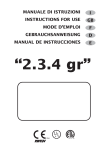
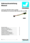
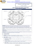
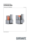
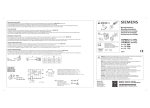
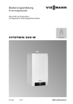
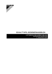
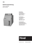
7213 8100 – 06/2005 EU
Serviceanleitung
Externe Störungsanzeige
Modul EM10 für UBA 3/EMS/MC10 Heizkessel
Serviceinstructie
Externe storingsaanduiding
EM10 voor UBA 3/EMS/MC10 cv-toestellen
Service instructions
External Error Detection
EM10 for UBA 3/EMS/MC10 boilers
Instructions d'utilisation
Détection de panne externe
EM10 pour chaudières avec UBA 3/EMS/MC10
Istruzioni d’uso
Avviso di disfunzione esterna
Modulo EM10 per caldaie con UBA 3/EMS/
MC10
Deutsch . . . . . . . . . . . . . . . . . . . . . . . . . . . . . . . . .3
Nederlands . . . . . . . . . . . . . . . . . . . . . . . . . . . . . .6
English . . . . . . . . . . . . . . . . . . . . . . . . . . . . . . . . .9
Français . . . . . . . . . . . . . . . . . . . . . . . . . . . . . . .12
Italiano . . . . . . . . . . . . . . . . . . . . . . . . . . . . . . . .15
Das Gerät entspricht den grundlegenden Anforderungen der
zutreffenden europäischen Richtlinien.
Die Konformität wurde nachgewiesen. Die entsprechenden
Unterlagen und das Original der Konformitätserklärung sind beim
Hersteller hinterlegt.
Dit apparaat voldoet aan de eisen van de betreffende Europese
richtlijnen.
Conformiteit is aangetoond. De betreffende documenten en de
originele conformiteitsverklaring zijn bij de fabrikant gedeponeerd.
This appliance is in conformance with the requirements of the
applicable European directives.
Conformity has been substantiated by the proper documents
which - together with the declaration of conformity - are filed with
the manufacturer.
Cet appareil répond aux exigences de base des directives
européennes correspondantes.
La conformité a été prouvée. La documentation correspondante
ainsi que l’original de la déclaration de conformité ont été déposés
auprès du fabricant.
L’apparecchio è conforme alle esigenze basilari delle pertinenti
direttive europee.
La conformità dell’impianto è stata certificata. La documentazione
corrispondente unitamente all'originale della dichiarazione di
conformità sono disponibili presso il costruttore.
2
06/2005
Modul EM10
Deutsch
Deutsch
Bestimmungsgemäße Verwendung
AS (24V)
z Das Modul EM10 kann an einen Heizkessel mit
UBA 3/EMS/MC10 angeschlossen werden.
AS (230V)
Funktion des Moduls EM10
– Das Modul EM10 meldet alle verriegelnden Fehler.
Anlagenfehler und Wartungsmeldungen erzeugen keine
Sammelstörmeldung.
– Das Modul EM10 reagiert nicht auf Störungen externer
Regelungen, die an den Heizkessel angeschlossen sind.
– Zusätzlich kann der Sollwert der Vorlauftemperatur des
Heizkessels über eine externe Steuerspannung von
0 – 10 V (Gleichspannung) vorgegeben werden.
– Oder kann die Leistung anhand eines externen Steuerungssignals gesteuert werden.
1
Montage
z Montieren Sie das Modul EM10 wie in der beiliegenden
"Montageanweisung Funktionsmodul xM10"
beschrieben.
Anschluss
z Das Modul EM10 über ein zweiadriges Kabel vom
Anschluss EMS (Abb. 1, Pos. 1) an den RC-Anschluss
der Klemmenleiste des Heizkessels (Abb. 1, Pos. 2)
anschließen. Der Anschluss ist polaritätsabhängig.
2
Abb. 1
Störmeldung
Die vom Modul EM10 generierte Störmeldung wird in
2 unterschiedlichen Formen ausgegeben:
a) AS 24 V-Kontakt (Abb. 2, Pos. 1)
Bei dem AS 24 V-Kontakt handelt es sich um einen potenzialfreien Umschaltkontakt für Signalkleinspannung bis
24V, der z.B. von einem Gebäudeautomationssystem
ausgewertet werden kann.
AS 24V
keine Störung
Störung
1 und 2
unterbrochen
geschlossen
2 und 3
geschlossen
unterbrochen
Siehe auch "Elektrischer Schaltplan", auf Seite 19.
b) AS 230V-Kontakt (Abb. 2, Pos. 2)
Bei dem AS 230V-Kontakt handelt es sich um einen
230V-Kontakt, der z.B. zum Ansteuern von einer Hupe oder
Störmeldelampe verwendet werden kann.
Bei Störung liegt an 2 und 4 des AS 230V-Anschlusses
230V Spannung an. Das Störungssignal wird aktiv, wenn:
– der UBA 3 eine verriegelnde Störung hat, oder
– der Anlagendruck zu niedrig ist, oder
– die Kommunikation mit dem Heizkessel seit mindestens
5 Minuten unterbrochen ist.
Änderungen aufgrund technischer Verbesserungen vorbehalten!
Modul EM10 • 06/2005
Anschluss Modul EM10 an Heizkessel
(als Beispiel hier: Logamax plus GB142
und eine Wandmontage der Module)
AS (24V)
AS (230V)
3
Abb. 2
2
1
4
Anschlüsse
W
3
Deutsch
Modul EM10
Der EM 10 kann als Interface zwischen dem Heizkessel und
beispielsweise einem Gebäudeverwaltungssystem
verwendet werden.
Anhand eines 0-10 VDC-Signals ist eine Steuerung über
die Leistung sowie über die Vorlauftemperatur möglich
(Abb. 3).
Steuerung über die Vorlauftemperatur
Der EM 10 überträgt das 0-10V-Signal des Gebäudeverwaltungssystems auf einen Vorlauftemperatursetpoint. Hierbei
handelt es sich um ein lineares Verhältnis (Tabelle 1).
Eingangsspannung [V]
Vorlauftemperatur-setpoint
(Heizkessel) [°C]
Zustand des
Heizkessels
0
0
aus
0,5
0
aus
0,6
± 15
ein
5,0
± 50
ein
10,0
± 90
ein / maximum
Tab. 1
Vorlauftemperatur [°C]
Externes Steuerungssignal 0-10V
Abb. 3
Volt
0 – 10V Diagramm
Steuerung über die Vorlauftemperatur
Steuerung über die Leistung
Der EM10 überträgt das Signal des Gebäudeverwaltungssystems auf einen Leistungssetpoint. Hierbei handelt es
sich um ein lineares Verhältnis (Tabelle 2).
Eingangsspannung [V]
Tab. 2
Leistungssetpoint
(Heizkessel) [%]
Zustand des
Heizkessels
0
0
aus
0,5
0
aus
0,6
±6
Niedriglast *)
5,0
± 50
Teillast
10,0
100
Volllast
Steuerung über die Leistung
*)Die Leistung bei Niedriglast ist vom Gerätetyp abhängig. Wenn
die Niedriglast des Geräts beispielsweise 20% beträgt und das
Steuerungssignal 1 Volt (= 10%) ist, dann ist die Sollleistung
kleiner als die Niedriglast. In diesem Fall liefert das Gerät 10%
durch einen Ein/Aus-Zyklus bei Niedriglast. In diesem Beispiel
geht der Heiskessel ab einem Setpoint von 2 Volt in
Dauerbetrieb.
Zur Aktivierung der Leistungsregelung muss eine Überbrükkung am Lüsterklemmenanschluss des EM10 eingesetzt
werden. Siehe "Anschlussschema EM 10" auf Seite 19.
W
4
Änderungen aufgrund technischer Verbesserungen vorbehalten!
Modul EM10 • 06/2005
Modul EM10
Deutsch
Anschluss weiterer Module
Sie können mehrere unterschiedliche Module (z. B. EM10
und VM10) miteinander verbinden.
Um zwei oder mehr Module miteinander zu verbinden, kann
der Netzanschluss (Abb. 4, Pos. 2) und der EMS-Anschluss
(Abb. 4, Pos. 3) jeweils weiterverbunden werden.
3
Netzanschluss
12
z Stellen Sie den Netzanschluss her (Abb. 4, Pos. 1 und
Abb. 2, Pos. 3).
2
3
Abb. 4
Zwei Module miteinander verbinden,
Netzanschluss herstellen
LED-Anzeigen am Modul EM10
Es gibt eine LED, die entweder rot oder grün leuchten kann.
Die LED blinkt kurz rot, wenn die Netzspannung eingeschaltet wird.
Zustand LED
Bedeutung
grün (ständig)
Alles ist richtig angeschlossen.
grün (blinkend)
Kommunikation mit dem Heizkessel ist seit
mindestens 5 Minuten unterbrochen.
Reset durchführen.
Zeigt der Reset keine Wirkung,
Heizungsfachfirma verständigen.
Siehe hierzu die Unterlagen des
Heizkessels.
EM10 ist defekt.
Heizungsfachfirma verständigen.
Siehe hierzu die Unterlagen des
Heizkessels.
rot (ständig)
Änderungen aufgrund technischer Verbesserungen vorbehalten!
Modul EM10 • 06/2005
W
5
Nederlands
Module EM10
Nederlands
Toepasbaarheid
AS (24V)
z De Module EM10 kan op een cv-toestel - voorzien van
een UBA3/EMS/MC10 - aangesloten worden.
AS (230V)
Functie van de module
– De EM10 meldt alle vergrendelende storingen.
Systeemfouten, onderhoudsmeldingen en blokkerende
storingenworden niet gemeld.
– De module EM10 reageert niet op storingen van externe
regelapparatuur, die op het cv-toestel zijn aangesloten.
– Tevens kan ook de aanvoertemperatuur van het
cv-toestel aangepast worden met een extern
stuursignaal van 0-10V (gelijkspanning)
– Of kan met een extern stuursignaal het vermogen
gestuurd worden.
1
Montage
z Monteer de module EM10 zoals beschreven in de
bijgevoegde "Montageinstructie functiemodule xM10".
Aansluiten
De module EM10 d.m.v. een 2-adrige kabel aan de
aansluiting EMS (afb. 1, pos. 1) en aan de RC-aansluiting
van het cv-toestel aansluiten (afb. 1, pos. 2). De aansluiting
is polariteitsgevoelig.
Storingssignaal
2
Afb. 1
Het door de EM10 gegenereerde storingssignaal wordt op
twee manieren gegeven:
a) De AS 24V aansluiting (afb. 2, pos. 1)
Bij de AS 24V aansluiting gaat het om een potentiaal vrij
schakelcontact voor laagspanningssignalen tot 24V, die
bijv. door een gebouwbeheersysteem uitgelezen kan
worden.
AS 24V
geen storing
storing
1 en 2
onderbroken
gesloten
2 en 3
gesloten
onderbroken
Zie hoofdstuk "Aansluitschema", bladzijde 19.
b) De AS 230V aansluiting (afb. 2, pos. 2)
Bij de AS 230V aansluiting gaat het om een 230V
aansluiting, voor het aansturen van bijvoorbeeld een
claxon of alarmlamp.
Bij storing staat op pin 2 en 4 van deze aansluiting 230V
spanning. Het storingssignaal wordt actief op het moment
dat:
– de UBA3 een vergrendelende storing heeft of,
– de systeemdruk te laag is of,
– de communicatie met het cv-toestel tenminste 5 minuten
is verbroken.
Aansluiten van de module op het
cv-toestel (Als voorbeeld is hier de
Logamax plus GB142 met een
wandmontage van de module afgebeeld)
AS (24V)
AS (230V)
3
Afb. 2
2
1
4
Aansluitingen
Wijzigingen voorbehouden!
6
Module EM10 • 06/2005
Module EM10
Nederlands
De EM10 kan gebruikt worden als interface tussen het
cv-toestel en bijvoorbeeld een gebouwbeheersysteem.
Door middel van een 0-10 VDC signaal kan zowel op
vermogen als op aanvoertemperatuur worden gestuurd.
(afb. 3).
Sturing op aanvoertemperatuur
De EM10 vertaalt het 0-10V signaal van het gebouwbeheersyteem naar een aanvoertemperatuursetpoint.
Hierbij is het verband lineair (tabel 1).
Ingangsspanning [V]
Aanvoertemperatuursetpoint (cv-toestel) [°C]
Status
cv-toestel
0
0
uit
0,5
0
uit
0,6
± 15
aan
5,0
± 50
aan
10,0
± 90
aan / maximum
Tab. 1
aanvoertemperatuur [°C]
Extern stuursignaal 0-10V
Afb. 3
externe stuurspanning (V)
0 – 10V diagram
Sturing op aanvoertemperatuur
Sturing op vermogen
De EM10 vertaalt het signaal van het gebouwbeheersysteem naar een vermogenssetpoint. Hierbij is het
verband lineair (tabel 2).
Ingangsspanning [V]
Vermogenssetpoint
(cv-toestel) [%]
Status
cv-toestel
uit
0
0
0,5
0
uit
0,6
±6
laaglast *)
5,0
± 50
deellast
10,0
100
vollast
Tab. 2
Sturing op vermogen
*)Het laaglastvermogen is toestelafhankelijk. Als de laaglast van
het toestel b.v. 20% is en het stuursignaal is 1 Volt (= 10%), dan
is het gevraagde vermogen kleiner dan de laaglast. In dit geval
gaat het toestel 10% leveren d.m.v. een aan/uit cyclus op
laaglast. In dit voorbeeld gaat het toestel vanaf een setpoint van
2 Volt in continu bedrijf.
Om de vermogensregeling te activeren dient een doorverbinding gemaakt te worden op de kroonsteenaansluiting
van de EM10. Zie het "Aansluitschema EM10" op pag. 19.
Wijzigingen voorbehouden!
Module EM10 • 06/2005
7
Nederlands
Module EM10
Het aansluiten van meerdere modules
Het is mogelijk om meerdere verschillende modules (bijv.
EM10 en VM10) met elkaar te verbinden.
Om twee of meer modules met elkaar te verbinden, kan de
netaansluiting (afb. 4, pos. 2) en de EMS-aansluiting
(afb. 4, pos. 3) steeds doorverbonden worden.
3
Netaansluiting
Sluit de netaansluiting aan (afb. 4, pos. 1 en afb. 2, pos. 3).
12
2
LED-meldingen op de EM10 module.
Er is 1 LED, die of rood of groen kan oplichten.
De LED knippert kortstondig rood, op het moment dat er
spanning op het cv-toestel komt te staan.
LED status
3
Afb. 4
Twee modules met elkaar verbinden,
Netspanning aansluiten
Betekenis
groen (permanent)
Alles is juist aangesloten.
groen(knipperend)
Minstens 5 minuten geen communicatie met het
cv-toestel.
Reset doorvoeren.
Helpt de reset niet, raadpleeg dan uw
installateur. Zie ook de instructies van
het cv-toestel.
rood (permanent)
EM10 is defect.
Bel uw installateur. Zie ook de
instructies van het cv-toestel.
Wijzigingen voorbehouden!
8
Module EM10 • 06/2005
Modul EM10
English
English
Range of application
AS (24V)
z The module EM10 may be installed in boilers equipped
with a UBA3/EMS/MC10.
AS (230V)
Function of the EM10
– The module EM10 relays a signal when a blocking
malfunction occurs in the boiler. System faults and
service announcements are not reported.
– The module EM10 does not react to malfunctions of any
external controllers which may be installed.
– In addition, the flow temperature of the boiler can be
influenced by means of an external control voltage of
0 – 10 V (rectified voltage).
– Or can be used to control the power using an external
control signal.
1
Mounting
z Mount the module EM10 as described in "Mounting
instructions function module xM10".
Connection
z Connect the module EM10 with a two-core cable leading
from the EMS-connection (fig. 1, pos. 1) to the
RC-connection on the external connection board of the
boiler (fig. 1, pos. 2). The connection is polarity sensitive.
2
Fig. 1 Connection module to the boiler (example
pictured: shows the Logamax plus GB142
with a wall-mounted module)
Malfunction signal
The generated malfunction signal is given in two ways:
a) AS 24V connection (fig. 2, pos. 1)
The AS 24V connection is a volt-free connection for low
voltage malfunction signals of up to 24V, which can be
evaluated by an automated building control system.
AS (24V)
AS 24V
connection
no malfunction
malfunction
1 and 2
interrupted
closed
2 and 3
closed
interrupted
See also the "Wiring Diagram" on page 19.
b) AS 230V connection (fig. 2, pos. 2)
The AS 230V connection is a 230V connection which can
be used to pass on an external malfunction signal to a
horn or warning light. At times of a malfunction, there will
be 230V on connections 2 and 4. The malfunction signal
is active when:
– the UBA 3 has a locking fault code, or
– the system pressure is too low, or
– there has been no communication with the boiler for at
least 5 minutes.
AS (230V)
3
2
1
4
Fig. 2 Connections
Subject to changes due to technical improvements!
Module EM10 • 06/2005
9
English
Module EM10
The EM 10 can be used as the interface between the boiler
assembly and a building management system for example.
A 0-10 VDC signal can be used to enable power-based or
flow temperature-based control (fig. 3).
Flow temperature-based control
The EM 10 transfers the 0-10V signal from the building
management system to a flow temperature set point.
This is a linear ratio (table 1).
Input voltage
[V]
Flow temperature set point
(boiler) [°C]
Boiler
condition
0
0
off
0.5
0
off
0.6
± 15
on
5.0
± 50
on
10.0
± 90
on / maximum
Table 1
flow temperature [°C]
0 – 10V external control signal
external control voltage
Fig. 3 0 – 10V Diagram
Flow temperature-based control
Power-based control
The EM 10 transfers the signal from the building management system to a power set point.
This is a linear ratio (table 2).
Input voltage
[V]
Power set point
(boiler) [%]
Boiler
condition
0
0
off
0.5
0
off
0.6
±6
low load *)
5.0
± 50
partial load
10.0
100
full load
Table 2
Power-based control
*)The low-load power depends on the type of appliance. For
example, if the low load of the appliance is 20% and the control
signal 1 volt (= 10%), the target power is lower than the low load.
In this case the appliance delivers 10% using an on/off cycle
with low load operation. In this example the boiler assembly
starts heating continuously from a set point of 2 volts.
To activate the power regulation the EM10 connectors
must be bridged. See the "EM 10 connection diagram"
on page 19.
Subject to changes due to technical improvements!
10
Module EM10 • 06/2005
Modul EM10
English
Connecting several modules
It is possible to connect several different modules
(Eg. EM10 and VM10) to each other.
To connect two or more modules, interconnect the mains
connections (fig. 4, pos. 2) and the EMS-connections
(fig. 4, pos. 3).
3
Mains connection
12
z Install the mains connection (fig. 4, pos. 1 and fig. 2,
pos. 3).
2
3
Fig. 4 Connecting two modules to each other,
installing the mains connection
LED-reports of the module EM10
There is one LED which can light up red or green.
The LED flashes red for a short time, when the mains power
is turned on.
LED status
green (permanent)
Meaning
Everything is connected properly.
green (flashing)
No communication with the boiler for at least 5
minutes.
Reset the boiler.
If the reset doesn’t work contact your
installer. See also the instructions for
the boiler.
red (permanent)
EM10 is defect.
Contact your installer. See also the
instructions for the boiler.
Subject to changes due to technical improvements!
Module EM10 • 06/2005
11
Français
Module EM10
Français
Utilisation appropriée
z Le module EM10 peut être branché à une chaudière
avec UBA 3/EMS/MC10.
Fonction du module EM10
– Le module EM10 signale tous les défauts verrouillants.
Les modules de l’installation et les messages de
maintenance ne génèrent pas de message de défauts
groupés.
– Le module EM10 ne réagit pas à des défauts de
régulations externes, raccordées à la chaudière.
– De plus, la consigne de la température de départ de la
chaudière peut être définie par une tension de
commande externe de 0 – 10 V (tension continue).
– Ou la puissance peut être pilotée au moyen d'un signal
de commande externe.
Montage
z Monter le module EM10 comme décrit dans la "Notice de
montage du module de fonction xM10" ci-joint.
Raccordement
z Raccorder le module EM10 à l'aide d'un câble à 2
conducteurs de la borne EMS (fig. 1, pos. 1) à la borne
RC du bornier de la chaudière (fig. 1, pos. 2).
Respecter la polarité lors du branchement.
AS (24V)
AS (230V)
1
2
Fig. 1 Branchement du module EM10 à la
chaudière (Exemple ci-dessus : Logamax
plus GB142 et un montage mural des
modules)
Message de défaut (voir aussi le schéma électrique)
Le message de défaut généré par le module EM10 est émis
sous deux formes différentes :
a) Contact AS 24 V (fig. 2, pos. 1)
Le contact AS 24 V est un contact inverseur isolé pour très
basse tension jusqu’à 24 V, qui peut être exploité p. ex. par
un système d'automatisation de bâtiment.
AS24V
1 et 2
2 et 3
aucun
ouvert
fermé
défaut
fermé
ouvert
b) Contact AS 230 V (fig. 2, pos. 2)
Le contact AS 230 V est un contact de 230 V, qui peut être
utilisé par exemple pour commander un avertisseur sonore
ou une lampe d’avertissement. En cas de défaut, une
tension de 230 V est présente sur les bornes 2 et 4 du
AS 230V.
Le signal de défaut est activé si :
AS (24V)
AS (230V)
3
2
1
4
Fig. 2 Bornes
– l'UBA 3 présente un défaut verrouillant ou
– la pression de l'installation est trop basse ou
– la communication avec la chaudière est interrompue
depuis au moins 5 minutes.
Sous réserve de modifications techniques !
12
Module EM10 • 06/2005
Module EM10
Français
Le EM 10 peut être utilisé comme interface entre la
chaudière et par exemple un système de gestion de
bâtiment.
Une commande est possible à l'aide d'un signal 0-10 VDC
par la puissance et par la température de départ (fig. 3).
Commande par la température de départ
Le EM 10 transmet le signal 0-10V du système de gestion à
un SetPoint de la température de départ. Il s'agit ici d'un
rapport linéaire (tableau 1).
Tension
d'entrée [V]
SetPoint température de
départ (chaudière) [°C]
Etat de la
chaudière
0
0
arrêt
0,5
0
arrêt
0,6
± 15
marche
5,0
± 50
marche
10,0
± 90
marche / maximum
Température de départ [°C]
Signal de commande externe 0-10V
volts
Fig. 3 Caractéristique 0 – 10V
Tableau 1 Commande par la température de départ
Commande par la puissance
Le EM10 transmet le signal du système de gestion à un
SetPoint de puissance. Il s'agit ici d'un rapport linéaire
(tableau 2).
Tension
d'entrée [V]
SetPoint de puissance
(chaudière) [%]
Etat de la
chaudière
arrêt
0
0
0,5
0
arrêt
0,6
±6
petite charge *)
5,0
± 50
charge partielle
10,0
100
pleine charge
Tableau 2 Commande par la puissance
*)La puissance avec petite charge est fonction du modèle de
l'appareil. Si la petite charge de l'appareil est par exemple de
20% et le signal de commande de 1 Volt (= 10 %), la puissance
théorique est inférieure à la petite charge. Dans ce cas,
l'appareil fournit 10 % par un cycle marche/arrêt avec petite
charge. Dans cet exemple, la chaudière se met sur
fonctionnement permanent à partir d'un SetPoint de 2 Volt.
Pour activer la régulation de puissance, il faut installer un
pontage au niveau du raccordement du bloc de jonction du
EM10. Voir "Schéma de raccordement EM 10", page 19.
Sous réserve de modifications techniques !
Module EM10 • 06/2005
13
Français
Module EM10
Branchement de plusieurs modules
Vous pouvez relier plusieurs modules différents
(p. ex. EM10 et VM10).
Pour relier deux ou plusieurs modules, la borne secteur
(fig. 4, pos. 2) et la borne EMS (fig. 4, pos. 3) peuvent être
reliés à d'autres composants.
3
Raccordement secteur
12
z Effectuer le raccordement au secteur (fig. 4, pos. 1 et
fig. 2, pos. 3).
2
3
Fig. 4 Relier deux modules, effectuer le
branchement au secteur
Affichages LED sur le module EM10
Le LED s'allume (vert ou rouge).
Le LED clignote (rouge), lorsque la tension secteur est
présente.
Etat LED
vert (en permanence)
vert (clignotant)
rouge (en permanence)
Signification
Tout est correctement branché.
la communication avec la chaudière est
interrompue depuis au moins 5 minutes.
Faire une remise à zéro.
Si la remise à zéro n'a aucun effet,
contacter l'installateur. Voir
documentation technique de la
chaudière.
L'EM10 est défectueux.
Contacter l'installateur. Voir
documentation technique de la
chaudière.
Sous réserve de modifications techniques !
14
Module EM10 • 06/2005
Modulo EM10
Italiano
Italiano
Utilizzo appropriato
z Il modulo EM10 può essere collegato alla caldaia dotata
di UBA 3/EMS/MC10.
Funzione del modulo EM10
– Il modulo EM10 segnala tutti gli errori di blocco
temporaneo. Gli errori d’impianto e gli avvisi di
manutenzione non generano alcun avviso di anomalia
generale.
– Il modulo EM10 non reagisce ai guasti di regolazioni
esterne collegate alla caldaia.
– Inoltre si può preimpostare il valore nominale della
temperatura di mandata della caldaia mediante una
tensione di controllo esterna di 0 – 10 V (tensione
continua).
– Oppure la potenza può essere comandata mediante un
segnale di comando esterno.
Montaggio
z Montare il modulo EM10 come descritto nelle "Istruzioni
di montaggio del modulo funzione xM10" allegate.
Collegamento
z Collegare il modulo EM10 con un cavo bipolare dal
morsetto EMS (fig. 1, pos. 1) al morsetto RC della
morsettiera della caldaia (fig. 1, pos. 2). L’attacco deve
rispettare la polarità.
AS (24V)
AS (230V)
1
2
Fig. 1
Collegamento del modulo EM10 alla
caldaia (esempio: Logamax plus GB142
e un montaggio a parete dei moduli)
Avviso anomalia
L’avviso anomalia generato dal modulo EM10 viene
emesso in 2 forme differenti:
a) Contatto AS 24 V (fig. 2, pos. 1)
Il contatto AS 24 V è costituito da un contatto di commutazione senza potenziale per un segnale a bassa tensione,
che può essere letto da un sistema di automazione degli
edifici.
AS 24V
1e2
2e3
Nessuna disfunzione Disfunzione
interrotto
chiuso
chiuso
interrotto
Cfr. anche "Schema elettrico" a pagina 19.
b) Contatto AS 230V (fig. 2, pos. 2)
Il contatto AS 230V è costituito da un contatto a 230 V, che
può essere usato ad es. per comandare una sirena oppure
una lampada di segnalazione.
In caso di anomalia, su 2 e 4 dell’attacco AS 230V è
presente una tensione di 230V. Il segnale di guasto viene
attivato se:
– sull’UBA 3 è presente un errore di blocco, oppure
– la pressione dell'impianto è troppo bassa, oppure
– la comunicazione con la caldaia è interrotta da almeno
5 minuti.
AS (24V)
AS (230V)
3
Fig. 2
2
1
4
Collegamenti
Il produttore si riserva il diritto di apportare qualsiasi modifica a fini di miglioramenti tecnici!
Modulo EM10 • 06/2005
15
Italiano
Modulo EM10
P.e. EM 10 può essere utilizzato come interfaccia fra la
caldaia e un sistema di gestione dell'immobile.
Un segnale 0-10 VDC rende possibile il comando attraverso
la potenza e la temperatura di preriscaldamento (fig. 3).
Comando attraverso temperatura di preriscaldamento
EM 10 trasferisce il segnale 0-10V del sistema di gestione
dell'immobile a un punto di impostazione della temperatura
di preriscaldamento. Si tratta di un rapporto lineare
(tabella 1).
Tensione di
ingresso
[V]
Setpoint temperatura
preriscaldamento (caldaia)
[°C]
Condizione
caldaia
0
0
spenta
Fig. 3
0,5
0
spenta
0,6
± 15
accesa
5,0
± 50
accesa
10,0
± 90
accesa / max.
Tab. 1
Temperatura di mandata [°C]
Segnale di comando esterno 0-10V
Volt
Diagramma 0 – 10V
Comando attraverso temperatura di preriscaldamento
Comando attraverso potenza
EM 10 trasferisce il segnale 0-10V del sistema di gestione
dell'immobile a un setpoint della temperatura di preriscaldamento. Si tratta di un rapporto lineare (tabella 2).
Tensione di
ingresso
[V]
Setpoint potenza
(caldaia)
[%]
Condizione
caldaia
spenta
0
0
0,5
0
spenta
0,6
±6
carico basso *)
5,0
± 50
carico parziale
10,0
100
pieno carico
Tab. 2
Comando attraverso potenza
*)In caso di carico basso, la potenza dipende dal tipo di
apparecchio. P.e. se il carico basso dell'apparecchio è pari al
20% e il segnale di comando è pari a 1 Volt (=10%), la potenza
nominale sarà inferiore al carico basso. In questo caso
l'apparecchio fornirà il 10% utilizzando un ciclo di acceso/
spento con carico basso. In questo esempio la caldaia a partire
dal setpoint di 2 Volt sarà in funzionamento continuo.
Per l'attivazione della regolazione della potenza deve
essere utilizzato un cavallotto sul collegamento con
morsetto da lampadario dell'EM10.
Vedi "Schema collegamento EM 10" a pag. 19.
Il produttore si riserva il diritto di apportare qualsiasi modifica a fini di miglioramenti tecnici!
16
Modulo EM10 • 06/2005
Modulo EM10
Italiano
Collegamento di ulteriori moduli
Si possono collegare tra loro più moduli diversi (ad es.
EM10 e VM10).
Per collegare tra loro due o più moduli, l’allacciamento alla
rete (fig. 4, pos. 2) e il morsetto EMS (fig. 4, pos. 3)
possono essere collegati in successione.
3
Allacciamento alla rete
2
12
z Realizzare l’allacciamento alla rete (fig. 4, pos. 1 e fig. 2,
pos. 3).
3
Fig. 4
Collegare tra loro due moduli, realizzare
l’allacciamento alla rete
LED sul modulo EM10
È presente un LED, che può accendersi con luce rossa
oppure verde.
Il LED lampeggia brevemente con luce rossa quando viene
inserita la tensione di rete.
Stato del LED
verde (continuo)
verde (lampeggiante)
rosso (continuo)
Significato
Tutto è correttamente collegato.
La comunicazione con la caldaia è interrotta da
almeno 5 minuti.
Eseguire il reset.
Se il reset non produce alcun effetto,
rivolgersi all’installatore. Si veda in
proposito la documentazione della
caldaia.
L’EM10 è difettoso.
Rivolgersi all’installatore. Si veda in
proposito la documentazione della
caldaia.
Il produttore si riserva il diritto di apportare qualsiasi modifica a fini di miglioramenti tecnici!
Modulo EM10 • 06/2005
17
18
06/2005
Elektrischer Schaltplan
Aansluitschema
Wiring Diagram
Schéma électrique
Schema elettrico
*)
Eingang
Netzspannung
Ausgang Netzspannung
(zum nächsten Modul)
Ingang
Netspanning
Uitgang Netspanning
(naar volgend Module)
Input mains
supply
Output mains suppy (to
following module)
Entrée tension
secteur
Sortie basse tension
(vers le module suivant)
Ingresso tensione
di rete
Alarmausgang
Niederspannung
Alarmuitgang
laagspanning
Alarm output
low voltage
Uscita tensione di rete
(al modulo successivo)
Sortie d'alarme
basse tension
Uscita allarme
bassa tensione
0V
Eingang
0 – 10V Signal
Ingang
0 – 10V signaal
Ausgang EMS-Bus (zum
nächsten Modul)
Input 0 – 10V signal
Uitgang EMS bus (naar
volgend Module)
Entrée signal
0 – 10V
Ingresso
segnale 0 – 10V
*) Für die Leistungsregelung:
Stift 1 und 3 überbrücken.
Voor vermogensregeling:
pin 1 en 3 doorverbinden.
For power control:
bridge pins 1 and 3
Pour la régulation de puissance :
Ponter la cheville 1 et 3.
Per la regolazione della potenza:
cavallottare perno 1 e 3.
06/2005
Alarmausgang 230V
(Lampe, Sirene ...)
Alarmuitgang 230V
(lamp, sirene ...)
Alarm output 230V
(lamp, sirene..)
Output EMS bus
Eingang EMS(to following module)
Bus
Sortie bus EMS (vers le
Ingang EMS
module suivant)
bus
Uscita bus EMS (al modulo
Input EMS bus
successivo)
Entrée bus
EMS
Ingresso bus
EMS
Sortie d'alarme 230V
(lampe, sirène...)
Uscita allarme 230V
(lampada, sirena ...)
19
721.381A - 4285 - 06/2005
Heizungsfachbetrieb/Verwarmingsspecialist/Heating system specialist
Installateur agréé de chauffage/Ditta specializzata nel riscaldamento: