1
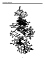
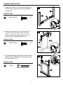
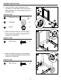
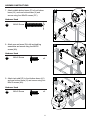
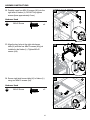
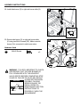
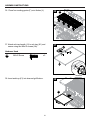
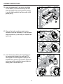
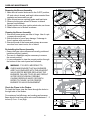
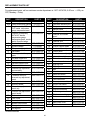
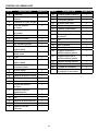
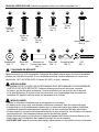
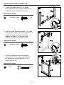
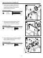
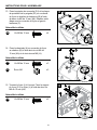
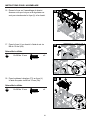
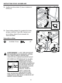
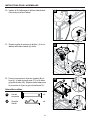
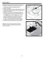
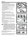
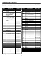
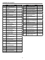
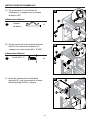
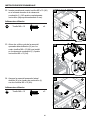
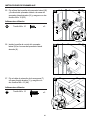
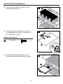
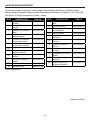
x2
Wrench*
Qty. 1
HH
II
GG
HH
27
2
17
Locking
pin
Wrench*
Qty. 5
1
N
1
M8
Washer
Nut
WheelM6
axle
M6 Nut
M8
Nut
WheelM8
axle
sleeve
pin
Nutsleeve Locking
Qty. 22
Qty.
Qty. 2
Qty. 53
Qty. 32
JJ
KK
II
JJ
26
GG
M6x15 Screw
M6x35 Screw
Qty. 4
M6x30 Screw
Qty. 4
M6x15 Screw
Qty. 65
M6x15 Screw
Qty. 65
AA
EE
M6x30 Screw
Qty.Screw
4
M6x35
Qty. 4
M5x12 Screw
Qty. 8
CC
DD
BB
CC
AA
BB
AA
27. Attach hose retention wire (T) to right front leg
(Y) and secure using two M6x15 screws (AA).
K
1
KK
LL
x2
26. Install side burner control knob (N) to right side
burner table (K).
Hardware Used
Lid pin
Qty. 4
M
M4x10 Screw
M5x12
Qty.Screw
4
Qty. 8
M4x10 Screw
Qty. 4
FF
M4x10 Screw
DD
EE
EE
EE
FF
Hardware Used
M8 Washer
Qty. 2
25
25. Attach side burner knob bezel (M) and side
burner valve to right side burner table (K) and
secure using two M4x10 screws (EE).
LL
Lid pin
Qty. 4
ASSEMBLY INSTRUCTIONS
2
K
T
AA