1
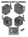
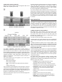
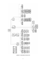
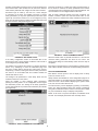
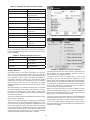
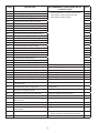
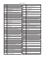
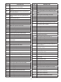
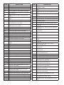
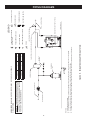
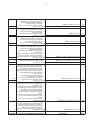
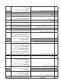
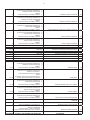
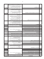
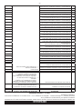
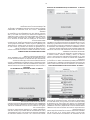
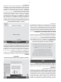
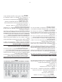
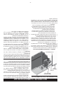
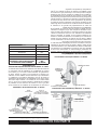
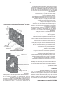
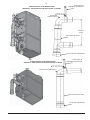
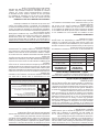
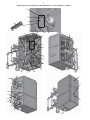
COMPONENT DESCRIPTION
19.Heat exchanger access covers
Allows access to the combustion side of the heat exchanger
coils.
1. Front access door:
Provides access to the gas train, burner controllers and the heat
exchanger.
20.High gas pressure switch
Switch provided to detect excessive supply gas pressure.
2. Air Filter Box:
Allows for the connection of the PVC air intake pipe to the boiler
through a standard PVC adapter. It uses a filter to prevent dust
and debris from entering the boiler.
21.Spark Igniter
Provides direct spark for igniting the burners.
22.Boiler power supply terminals (not visible)
The main power to the boiler is supplied through the terminals
housed inside the high voltage junction box.
3. Automatic air vents:
Designed to remove trapped air from the heat exchanger coils.
23.Low gas pressure switch
Switch provided to detect low gas supply pressure.
4. Blowers:
The blowers pull in air and gas through the venturis. Air and gas
mix inside the venturi and are pushed into the burners, where
they burn inside the combustion chamber.
24.High voltage connection box
This box has terminals for connecting the main power supply
(120V) to the boiler and outputs power supply (120V) for the
pumps from the boiler control. This box has terminals for low
voltage devices such as condensate trap and flow switch.
5. Boiler inlet temperature sensors
These sensors monitor system return water temperature.
6. Boiler outlet temperature sensors/High Limits
These sensors monitor boiler outlet water temperature. The boiler
modulates based on the Lead Lag Sensor connected to the tank.
25.Sensors/Communication Box
Connects sensors to tank sensor/header sensor and external
connections to building managements systems through MODBUS.
7. Burners
Made with metal fiber and stainless steel construction, the
burners use pre-mixed air and gas and provide a wide range of
firing rates.
26.Low water cutoff board and sensor probe (LWCO)
Device used to ensure adequate water is supplied to the boiler.
In the event of inadequate water levels, LWCO will ensure boiler
shut down. LWCO board is connected to the electronic panel,
whereas the sensor probe is connected to the heat exchanger.
8. Condensate Trap
Disposes the condensate produced from heat exchanger and
houses a switch that detects in case of blockage.
27.Main power supply switch
Turns 120 VAC ON/OFF to the boiler.
9. Control modules
The control modules respond to internal and external signals and
control the blowers, gas control valves, and pumps to meet the
heating demand.
28.Pump relay
The pump relays are used for providing power to the Boiler
models.
29.Pressure relief valve
Protects the heat exchangers from an over pressure condition.
The relief valve will be set at particular PSI, depending on models.
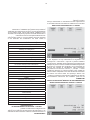
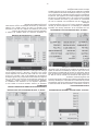
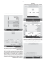
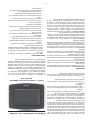
10.Touch Screen Display
Digital controls with touch screen technology and full color
display.
30.Reset switch (optional) (not visible)
Reset switch for the low water cutoff.
11.Sight glass
The quartz sight glass provides a view of the flame for inspection
purposes.
31.Stainless steel heat exchangers
Allows system water to flow through specially designed coils.
12.Flame sensors
This is used by the control module to detect the presence of
burner flame.
32.Venturi
The venturi is a gas/air mixing unit that allows modulation of a
premix burner with constant gas/air ratio.
13.Flap valves
Prevents recirculation of flue products when only one burner is
running.
33.Water inlet
Water connection that return water from the system to the heat
exchangers.
14.Flue gas sensors (not visible)
These sensors monitor the flue gas exit temperature. The control
modules will modulate and shut down the boiler if the flue gas
temperature gets too hot. This protects the flue pipe from
overheating.
34.Water outlets
A NPT water connection that supplies hot water to the system.
35. Enable/Disable Switch
This is an emergency boiler turn off switch which disconnects
the interlock voltage to the control board, hence turning off the
power supply to the gas control valves. Do not use this switch
for turning off the boiler, this should be done from the touch
screen display, using the Operational Switch on the Lead
Lag screen.
15.Flue pipe adapter (not visible)
Allows for the connection of the PVC vent pipe system to the
boiler.
16.Gas shutoff valves (Internal unit)
Manual valves used to isolate the gas control valves from the
burners.
36.Vent outlet
Provides an outlet for combustion gases to outdoor.
17.Main gas shutoff valve (External unit)
Manual valve used to isolate the boiler from the gas supply.
18.Automatic modulating gas valve
The gas valve with the addition of venturi and blower are used for
modulating premix appliances.
12