1
MEDUSA
Universal sphere for video surveillance
EN English - Instructions manual
IT Italiano - Manuale di istruzioni
FR Francais - Manuel d'instructions
DE Deutsch - Bedienungslanleitung
MEDUSA
Universal sphere for video surveillance
EN English - Instructions manual
Contents
EN - English - Instructions manual
ENGLISH
1 About this manual......................................................................................................... 3
1.1 Typographical conventions................................................................................................................................. 3
2 Notes on copyright and information on trademarks................................................. 3
3 Safety rules.................................................................................................................... 3
4 Identification................................................................................................................. 4
4.1 Product description and type designation.................................................................................................... 4
4.2 Product markings.................................................................................................................................................... 4
5 Preparing the product for use...................................................................................... 4
5.1 Safety precautions before use............................................................................................................................ 4
5.2 Contents and unpacking...................................................................................................................................... 4
5.3 Safely disposing of packaging material.......................................................................................................... 4
6 Installing and assembling............................................................................................. 5
6.1 Assembly.................................................................................................................................................................... 5
6.1.1 Assembling the plate with the cable glands................................................................................................................. 5
6.2 Installation................................................................................................................................................................. 5
6.2.1 Installing the housing............................................................................................................................................................ 5
6.3 Universal adapter.................................................................................................................................................... 6
6.3.1 Wiring.......................................................................................................................................................................................... 9
6.3.2 Earthing....................................................................................................................................................................................11
6.3.3 Closing the housing.............................................................................................................................................................11
6.3.4 Fan version...............................................................................................................................................................................11
7 Maintaining and cleaning........................................................................................... 12
7.1 Window and plastic cover cleaning................................................................................................................12
8 Disposal of waste materials........................................................................................ 12
9 Technical data.............................................................................................................. 12
9.1 General......................................................................................................................................................................12
9.2 Mechanical...............................................................................................................................................................12
9.3 Electrical...................................................................................................................................................................12
9.4 Environment............................................................................................................................................................12
9.5 Compliance to........................................................................................................................................................12
10 Technical drawings.................................................................................................... 13
2
3 Safety rules
Before installing and using this unit,
please read this manual carefully. Be sure
to keep it handy for later reference.
hh
1.1 Typographical conventions
DANGER!
High level hazard.
Risk of electric shock. Disconnect the
power supply before proceeding with any
operation, unless indicated otherwise.
gg
WARNING!
Medium level hazard.
This operation is very important for
the system to function properly. Please
read the procedure described very
carefully and carry it out as instructed.
hh
INFO
Description of system specifications.
We recommend reading this part
carefully in order to understand
the subsequent stages.
jj
The manufacturer declines all responsibility
for any damage caused by an improper use
of the appliances mentioned in this manual.
Furthermore, the manufacturer reserves
the right to modify its contents without
any prior notice. The documentation
contained in this manual has been
collected with great care, the manufacturer,
however, cannot take any liability for
its use. The same thing can be said for
any person or company involved in the
creation and production of this manual.
• The device must be installed only and
exclusively by qualified technical personnel.
• Before any technical work on the appliance,
disconnect the power supply.
• Do not use power supply cables
that seem worn or old.
• Never, under any circumstances, make any
changes or connections that are not shown in
this handbook: improper use of the appliance
can cause serious hazards, risking the safety
of personnel and of the installation.
2 Notes on copyright and
information on trademarks
• Use only original spare parts. Not original
spare parts could cause fire, electrical
discharge or other hazards.
The quoted names of products or companies
are trademarks or registered trademarks.
• Before proceeding with installation check the
supplied material to make sure it corresponds
to the order specification by examining the
identification labels ("4.2 Product markings", page 4).
3
EN - English - Instructions manual
1 About this manual
EN - English - Instructions manual
4 Identification
5.2 Contents and unpacking
4.1 Product description
and type designation
When the product is delivered, make sure that
the package is intact and that there are no
signs that it has been dropped or scratched.
Housing for discreet surveillance that can be used
in both indoor and outdoor installations. It is
designed to be camouflaged with normal lighting
systems. Easy to install, this model is able to house
a range of speed domes. The housing is mounted
with internal cable management bracket; the
bracket can be for wall, ceiling or parapet mount.
A wide range of accessories is available, including:
universal adapter plate for the various speed
dome models, PTC fan heater (single or triple)
and thermostat, camera power supply, sun
protection cover, opening protection alarm.
4.2 Product markings
See the label attached to the outside of the package.
5 Preparing the
product for use
Any change that is not expressly
approved by the manufacturer
will invalidate the guarantee.
hh
5.1 Safety precautions
before use
In the 115/230Vac powered configuration
it is necessary to insert a 1 0 unipolar
main switch (open contact distance
d>3mm) upstream on the power
line. This switch should be used to
disconnect the power supply before
carrying out any maintenance operation
or before opening the housing.
gg
4
If there are obvious signs of damage,
contact the supplier immediately.
Keep the packaging in case you need
to send the product for repairs.
Check the contents to make sure they correspond
with the list of materials as below:
Housing packing
• MEDUSA housing
• Housing equipment:
• Cable glands with nuts
• Plate for cable glands
• Gasket for plate
• Screws for plate
• Allen wrench
• Desiccant salt bag
Adapter packing
• Adapter
• Adapter equipment:
• Earthed cables
• Screws for fastening the camera
• Instructions manual
5.3 Safely disposing of
packaging material
The packaging material can all be recycled.
The installer technician will be responsible for
separating the material for disposal, and in
any case for compliance with the legislation
in force where the device is to be used.
Bear in mind that if the material has to be returned
due to a fault, using the original packaging
for its transport is strongly recommended.
6 Installing and assembling
6.1 Assembly
6.1.1 Assembling the plate
with the cable glands
This section describes how to assemble the plate
with cable glands that is supplied with the housing.
6.2.1 Installing the housing
EN - English - Instructions manual
Only specialised personnel should be
allowed to install and assemble the device.
hh
6.2 Installation
This operation must be carried out with
the power supply disconnected.
gg
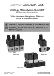
Attach the bracket firmly at the chosen spot.
Remove the housing cover by undoing
the 4 screws on the top and leave it
hanging from the anchorage cable.
Attach the cable glands facing the direction
shown, taking care to tighten the nuts properly.
Fig. 1
Attach the gasket by inserting the
screws into the holes in the plate and
then into the holes in the gasket.
Fig. 3
Insert the housing body into the coupling seat
provided and fasten it down immediately using
the two screws supplied with the support.
Fig. 2
If you are using a self-adhesive gasket
attach it to the plate in the same position.
hh
The plate is now ready for installation in the housing
Fig. 4
When carrying out these operations
take care not to scratch the dome.
hh
5
EN - English - Instructions manual
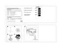
Remove the universal adapter for the
speed dome from the aluminium ring,
by undoing the three screws.
Crimp the various connectors onto the cables.
Attach the adapter ring inside the housing
using the 4 M4 screws supplied.
Take great care not to pinch or
damage the cables there.
hh
Fig. 7
6.3 Universal adapter
Dismantle the adapter by loosening the
three screws M3x12mm and then taking it
off the ring by turning it anti-clockwise.
Fig. 5
Pass the various wires and cables through the bracket
into the inside of the housing; these cables should
be locked by the cable glands on the plate supplied
with the housing. Then close the plate using the four
self-tapping triangular M3 slotted screws supplied.
Fig. 8
Prepare the camera adapter to the exact
length as given in table then fasten the
speed dome using the supplied screws.
Fig. 6
The stretch of cable that is left
inside the housing must be long
enough to reach and connect with
the speed dome being installed.
hh
6
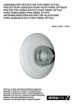
Universal adapter
Fixed plate
(Fig. 9)
Moving plate
(Fig. 10)
2130*
-
PM9
E
2
214
-
PM5
E
1
Spacer plate (Fig. 11)
Axis
Letter
215
-
PM10
E
2
-
PM11
E
2
233
JVC
Panasonic
Number
213*
231/232*
PF2
-
-
-
-
PM1
L
1
TK-C676**
-
PM3
L
1
VN-V685U/VN-V686U
-
PM12
D
1
TK-C685E/TK-C686E
-
PM13
D
1
BB-HCM381
-
PM8
G
2
WV-CS9500
PF1
-
-
-
WV-NS202E*
-
PM7
A
2
Sanyo
VCC 9300P
PF3
-
-
-
Sony
SNC RZ50P
-
PM4
A
1
SNC RZ25P
-
PM2
H
1
Toshiba
IK-WB21A*
-
PM6
G
2
Tab. 1
* It is also necessary to use the adapter supplied with the camera.
** Use hexagonal spacers M4x20mm.
PM9-PM11
PM3
PM4
PM6
PF2
PF1
PM2-PM5
PM12-PM13
PM7
PM3
PF2
PM1-PM10
PF3
PF2
PF3
PF1
PF1
PM7
PM6
PM4
Fig. 11
Fig. 10
Fixed plate.
1
1
2
2
PM4
PM7
PM10
PM6
PM7-PM8
PM10
PM7
PM8
PM4
PM8
PM1-PM3
PM12-PM13
PM9-PM11
Fig. 9
PM2-PM5
PM12-PM13
PM1-PM10
PF1
PF3
PF3
A
B
C
D
E
F
G
H
I
L
M
N
EN - English - Instructions manual
Speed Dome
PM3
PM2-PM5
Moving plate.
A
B
C
D
E
F
G
H
I
L
M
N
Spacer plate.
7
Bringing the adapter close to the ring, connect
the crimped cables to the speed dome.
EN - English - Instructions manual
Insert the adapter in its seating, turning it to couple
it with the screws M3x12mm. Tighten the screws.
Fig. 14
Fig. 12
Fasten on fixed plate.
Fig. 13
Fasten on moving plate.
The arrow at the bottom of the adapter
indicates the outside of the housing.
hh
8
6.3.1 Wiring
Complete the wiring as necessary, depending on the type of power supply to the particular speed dome:
Fig. 15
EN - English - Instructions manual
IN 230Vac
OUT 24Vac
Toroidal camera power supply, IN 230Vac - OUT 24Vac.
Blue
OUT 12Vdc
OUT 24Vdc*
Fig. 16
Black
IN 100-240Vac
OUT 230Vac
Wide range camera power supply, IN 100-240Vac - OUT 12/24Vdc/230Vac.
* The voltage depends on the bought power supply.
9
Red
OUT 24Vac
EN - English - Instructions manual
IN 24Vac
Fig. 17
Camera power supply, IN 24Vac - OUT 24Vac.
Red
IN 24Vac
Brown
OUT 12Vdc
Fig. 18
10
Camera power supply, IN 24Vac - OUT 12Vdc.
6.3.4 Fan version
If the input voltage is 230Vac, earth the housing
applying the two supplied cables to the cover and
body using M3*6T screws and the toothed washers.
Complete the cabling inserting the fastons into the
corresponding seats on the HEATER auxiliary board.
The fan version of the housing has two side
filters on the aluminium body, protected by the
cover, while two additional fans are installed
in the adapter ring, to circulate air from the
inside to the outside of the housing.
EN - English - Instructions manual
6.3.2 Earthing
Fig. 21
Fig. 19
6.3.3 Closing the housing
Disseccant
salt sachet
Fig. 22
This makes it possible to lower the temperature
difference between inside and outside when
the housing is used at high temperatures.
Using this application means the
housing will lose its IP66 rating.
Fig. 20
Take the dessicant salt sachet out of its transparent
pack and insert it into the pocket shown in figure.
Close the housing by positioning the cover correctly
and fastening the top down using the four screws
Only now is it possible
to power the housing
hh
11
EN - English - Instructions manual
7 Maintaining and cleaning
9.3 Electrical
7.1 Window and plastic
cover cleaning
Fan assisted heater, Ton 15°C +/-3°C (59°F +/-37°F)
Toff 22°C +/-3°C (71°F +/-37°F)
Wash with neutral soap and water.
Avoid ethyl alcohol, solvents,
hydrogenated hydrocarbide, strong
acid and alkali. Such products may
irreparably damage the plastic surfaces.
hh
8 Disposal of waste
materials
This symbol mark and recycle system
are applied only to EU countries
and not applied to the countries
in the other area of the world.
nn
-- IN 24Vac, consumption 24W max
-- IN 100/240Vac, consumption 44W max
Camera power supply included with internal adapter
-- IN 100/240Vac, 50/60Hz, OUT 12Vdc, 3A max
-- IN 100/240Vac, 50-60Hz, OUT 24Vdc, 1.5A max
-- IN 230Vac, 50/60Hz, OUT 24Vac, 2A max
-- IN 24Vac/24Vdc, 50/60Hz, OUT 12Vdc, 2A max
Blower in continuous duty for heater assistance
Ton 15°C +/-3°C (59°F +/-37°F) Toff 22°C +/-3°C (71°F
+/-37°F)
-- IN 12Vdc, consumption 4W max
Blower for air-exchange with thermostat Ton 35°C+/3°C (95°F +/-37°F) Toff 20°C+/-3°C (68°F +/-37°F)
-- IN 12Vdc, consumption 4W max
9.4 Environment
Your product is designed and manufactured
with high quality materials and components
which can be recycled and reused.
Indoor / Outdoor
This symbol means that electrical and electronic
equipment, at their end-of-life, should be disposed
of separately from your household waste.
Operating temperature with reinforced heater kit (to
be installed only with adapters ODBH18H series and
only with camera and lens options guaranteed to work
in operating temperatures down to -10° (14F°): -30°C /
+50°C (-22°F / +122°F)
Please dispose of this equipment at your local
Community waste collection or Recycling centre.
In the European Union there are separate collection
systems for used electrical and electronic products.
9 Technical data
9.1 General
Built in die-cast aluminium
Epoxypolyester powder painting, RAL9002 colour
Lower semisphere: in PMMA transparent or smoked (in
this case the loss of luminosity is 1 lux)
Sunshield in ABS for outdoor, RAL9002 colour
9.2 Mechanical
External dimensions with sunshield: Ø 351x335mm
(13.8x13.2in)
External dimensions without sunshield: Ø 314x322mm
(12.4x12.7in)
4 cable-glands: 3xM16 allowing Ø cable 3,5-7mm (0.10.3in), 1xM12 allowing Ø cable 5-10mm (0.2-0.4in)
Supplied with instruction manual, cable glands and
protection gasket
Unit Weight: DBH18 3.8kg / 8.4lb (without camera
adapter)
12
Operating temperature with standard fan-assisted
heater: -20°C / +60°C (-4°F / +140°F)
9.5 Compliance to
CE according to EN 61000-6-3, EN 60950-1, EN 50130-4
IP66 according to EN 60529
10 Technical drawings
244
91
335
A-A
A
Ø 185
A-A
FAN VERSION
Ø 351
Ø 230
368
240
B
B-B
B
Ø 184
138
240
C
C-C
Ø 184
Fig. 23
C
MEDUSA
13
EN - English - Instructions manual
Ø 314
A
VIDEOTEC S.p.A.
www.videotec.com
Printed in Italy
MNVCDBH18B_0919_EN
MEDUSA
Sfera universale per la sorveglianza video
IT Italiano - Manuale di istruzioni
Sommario
ITALIANO
1 Informazioni sul presente manuale............................................................................. 3
IT - Italiano - Manuale di istruzioni
1.1 Convenzioni tipografiche..................................................................................................................................... 3
2 Note sul copyright e informazioni sui marchi commerciali....................................... 3
3 Norme di sicurezza........................................................................................................ 3
4 Identificazione............................................................................................................... 4
4.1 Descrizione e designazione del prodotto...................................................................................................... 4
4.2 Marcatura del prodotto......................................................................................................................................... 4
5 Preparazione del prodotto per l’utilizzo..................................................................... 4
5.1 Precauzioni di sicurezza prima dell’utilizzo................................................................................................... 4
5.2 Contenuto e disimballaggio................................................................................................................................ 4
5.3 Smaltimento in sicurezza dei materiali di imballaggio.............................................................................. 4
6 Installazione e assemblaggio....................................................................................... 5
6.1 Assemblaggio........................................................................................................................................................... 5
6.1.1 Montaggio della piastrina con i pressacavi................................................................................................................... 5
6.2 Installazione.............................................................................................................................................................. 5
6.2.1 Installazione della custodia................................................................................................................................................. 5
6.3 Adattamento universale....................................................................................................................................... 6
6.3.1 Cablaggi...................................................................................................................................................................................... 9
6.3.2 Cablaggio di terra..................................................................................................................................................................11
6.3.3 Chiusura della custodia.......................................................................................................................................................11
6.3.4 Versione ventilata..................................................................................................................................................................11
7 Manutenzione e pulizia.............................................................................................. 12
7.1 Pulizia del vetro e delle parti in plastica........................................................................................................12
8 Smaltimento dei rifiuti................................................................................................ 12
9 Dati tecnici................................................................................................................... 12
9.1 Generale...................................................................................................................................................................12
9.2 Meccanica................................................................................................................................................................12
9.3 Elettrico.....................................................................................................................................................................12
9.4 Ambiente..................................................................................................................................................................12
9.5 Conformità...............................................................................................................................................................12
10 Disegni tecnici........................................................................................................... 13
2
1 Informazioni sul
presente manuale
1.1 Convenzioni tipografiche
PERICOLO!
Pericolosità elevata.
Rischio di scosse elettriche. Togliere
l'alimentazione prima di procedere con
le operazioni, salvo diversa indicazione.
gg
ATTENZIONE!
Pericolosità media.
L'operazione è molto importante per
il corretto funzionamento del sistema.
Si prega di leggere attentamente
la procedura indicata e di eseguirla
secondo le modalità previste.
hh
INFO
Descrizione delle caratteristiche del
sistema.
Si consiglia di leggere attentamente
per comprendere le fasi successive.
jj
2 Note sul copyright
e informazioni sui
marchi commerciali
I nomi di prodotto o di aziende citati sono
marchi commerciali o marchi commerciali
registrati appartenenti alle rispettive società.
Il produttore declina ogni responsabilità
per eventuali danni derivanti da un
uso improprio delle apparecchiature
menzionate in questo manuale. Si
riserva inoltre il diritto di modificarne il
contenuto senza preavviso. Ogni cura è
stata posta nella raccolta e nella verifica
della documentazione contenuta in
questo manuale, tuttavia il produttore
non può assumersi alcuna responsabilità
derivante dall'utilizzo della stessa.
Lo stesso dicasi per ogni persona o
società coinvolta nella creazione e
nella produzione di questo manuale.
hh
IT - Italiano - Manuale di istruzioni
Prima di installare e utilizzare questa unità, leggere
attentamente questo manuale. Conservare questo
manuale a portata di mano come riferimento futuro.
3 Norme di sicurezza
• L'installazione e la manutenzione del
dispositivo deve essere eseguita solo
da personale tecnico qualificato.
• Prima di effettuare interventi tecnici
sull'apparecchio togliere l'alimentazione elettrica.
• Non utilizzare cavi di alimentazione con
segni di usura o invecchiamento.
• Non effettuare per nessun motivo
alterazioni o collegamenti non previsti in
questo manuale: l'uso di apparecchi non
idonei può portare a gravi pericoli per la
sicurezza del personale e dell'impianto.
• Utilizzare solo parti di ricambio originali. Pezzi
di ricambio non originali potrebbero causare
incendi, scariche elettriche o altri pericoli.
• Prima di procedere con l'installazione controllare
che il materiale fornito corrisponda alle specifiche
richieste esaminando le etichette di marcatura
("4.2 Marcatura del prodotto", pagina 4).
3
IT - Italiano - Manuale di istruzioni
4 Identificazione
5.2 Contenuto e disimballaggio
4.1 Descrizione e
designazione del prodotto
Alla consegna del prodotto verificare che
l’imballo sia integro e non abbia segni
evidenti di cadute o abrasioni.
Custodia per la sorveglianza discreta utilizzabile
in installazioni interne o esterne. Il suo design
consente la mimetizzazione in normali sistemi
di illuminazione. Facile da installare, consente di
ospitare al suo interno svariati tipi di brandeggi
veloci (speed domes). La custodia viene montata con
supporto con passaggio interno dei cavi; il supporto
può essere da muro, soffitto o da parapetto.
É disponibile una gamma di accessori quali: piastra
di adattamento universale adatta ai vari modelli
di speed dome, riscaldamento (singolo o triplo)
a PTC ventilato e termostatato, alimentatore per
telecamera, tettuccio parasole, allarme anti-apertura.
4.2 Marcatura del prodotto
Vedere l’etichetta posta sull’esterno dell’imballo.
5 Preparazione del
prodotto per l’utilizzo
Qualsiasi cambiamento non
espressamente approvato dal
costruttore fa decadere la garanzia.
hh
5.1 Precauzioni di sicurezza
prima dell’utilizzo
In configurazione alimentata a
115/230Vac occorre inserire sulla linea di
alimentazione, a monte, un interruttore
generale unipolare 1 0 (distanza apertura
dei contatti d>3mm). Tale interruttore
deve essere utilizzato come mezzo di
separazione dell’alimentazione prima
di eseguire qualsiasi operazione di
manutenzione o apertura della custodia.
gg
4
In caso di evidenti segni di danno all’imballo
contattare immediatamente il fornitore.
Conservare l’imballo nel caso sia necessario
inviare il prodotto in riparazione.
Controllare che il contenuto sia rispondente
alla lista del materiale sotto indicata:
Imballaggio custodia
• Custodia MEDUSA
• Dotazione per custodia:
• Pressacavi con dadi
• Piastrima per pressacavi
• Guarnizione per piastrina
• Viti per piastrina
• Chiave a brugola
• Sacchetto sali essiccanti
Imballaggio adattamento
• Adattamento
• Dotazione per adattamento:
• Cablaggi di messa a terra
• Viti per fissaggio telecamera
• Manuale di istruzioni
5.3 Smaltimento in sicurezza
dei materiali di imballaggio
I materiali d’imballo sono costituiti interamente
da materiale riciclabile. Sarà cura del tecnico
installatore smaltirli secondo le modalità di
raccolta differenziata o comunque secondo
le norme vigenti nel Paese di utilizzo.
Si ricorda comunque che in caso di ritorno di
materiale con malfunzionamenti è consigliato
l’imballaggio originale per il trasporto.
6 Installazione e
assemblaggio
6.2 Installazione
6.2.1 Installazione della custodia
Operazione da effettuarsi in
assenza di tensione.
gg
6.1 Assemblaggio
Fissare saldamente la staffa utilizzata
nel luogo di destinazione.
6.1.1 Montaggio della
piastrina con i pressacavi
Smontare il coperchio della custodia
svitando le 4 viti nella parte superiore e
lasciarlo appeso al cavo di ancoraggio.
L’installazione e l’assemblaggio vanno
eseguiti solo da personale specializzato
IT - Italiano - Manuale di istruzioni
hh
Questo paragrafo descrive il montaggio della piastrina
con i pressacavi fornita nella dotazione della custodia.
Applicare i pressacavi nel verso indicato in
figura avendo cura di stringere bene i dadi.
Fig. 1
Applicare la guarnizione infilando le viti nei fori
della piastrina e poi nei fori della guarnizione.
Fig. 3
Inserire il corpo custodia nell’apposita sede di
accoppiamento e procedere subito al fissaggio
con le due viti in dotazione al supporto.
Fig. 2
Nel caso la guarnizione sia del tipo
adesivo applicarla sulla piastrina
nella medesima posizione.
hh
Ora la piastrina è pronta per essere
installata nella custodia.
Fig. 4
Durante le operazioni fare attenzione
a non graffiare la cupola.
hh
5
Smontare l’adattamento universale per la speed
dome dall’anello in alluminio svitando le tre viti.
Crimpare sui cavi i vari connettori da utilizzare.
IT - Italiano - Manuale di istruzioni
Fissare l’anello adattatore all’interno della custodia
tramite le 4 viti M4 fornite in dotazione.
Attenzione a non pizzicare o
rovinare i cablaggi presenti.
hh
Fig. 7
6.3 Adattamento universale
Smontare l’adattamento allentando le tre
viti M3x12mm e togliendolo dall’anello
con una rotazione antioraria.
Fig. 5
Passare i vari cablaggi attraverso la staffa fino
a giungere all’interno della custodia, tali cavi
dovranno essere bloccati con i pressacavi
della piastrina in dotazione. Procedere quindi
alla chiusura della piastrina con le quattro
viti autoformanti M3 trilobate fornite.
Fig. 8
Preparare l’adattamento per telecamera alla
lunghezza esatta secondo quanto riportato in tabella,
quindi fissarvi la speed dome con le viti in dotazione.
Fig. 6
Lo spezzone di cavo rimanente all’interno
della custodia dovrà avere una lunghezza
sufficiente ad essere collegato alla
speed dome in installazione.
hh
6
Adattamento universale
Piastra fissa
(Fig. 9)
Piastra mobile
(Fig. 10)
2130*
-
PM9
E
2
214
-
PM5
E
1
Speed Dome
Axis
Lettera
-
PM10
E
2
-
PM11
E
2
PF2
-
-
-
-
PM1
L
1
TK-C676**
-
PM3
L
1
VN-V685U/VN-V686U
-
PM12
D
1
TK-C685E/TK-C686E
-
PM13
D
1
BB-HCM381
-
PM8
G
2
WV-CS9500
PF1
-
-
-
WV-NS202E*
-
PM7
A
2
Sanyo
VCC 9300P
PF3
-
-
-
Sony
SNC RZ50P
-
PM4
A
1
SNC RZ25P
-
PM2
H
1
Toshiba
IK-WB21A*
-
PM6
G
2
Tab. 1
* È necessario utilizzare anche l'adattamento fornito in dotazione con la telecamera.
** Utilizzare distanziali esagonali M4x20mm.
PM9-PM11
PM3
PM4
PM6
PF2
PF1
PM2-PM5
PM12-PM13
PM7
PM3
PF2
PM1-PM10
PF3
PF2
PF3
PF1
PF1
PM7
PM6
PM4
Fig. 11
Fig. 10
Piastra fissa.
1
1
2
2
PM4
PM7
PM10
PM6
PM7-PM8
PM10
PM7
PM8
PM4
PM8
PM1-PM3
PM12-PM13
PM9-PM11
Fig. 9
PM2-PM5
PM12-PM13
PM1-PM10
PF1
PF3
PF3
A
B
C
D
E
F
G
H
I
L
M
N
IT - Italiano - Manuale di istruzioni
215
233
Panasonic
Numero
213*
231/232*
JVC
Piastra distanziale (Fig. 11)
PM3
PM2-PM5
Piastra mobile.
A
B
C
D
E
F
G
H
I
L
M
N
Piastra distanziale.
7
Avvicinando l’adattamento all’anello, connettere i
cavi precedentemente crimpati alla speed dome.
IT - Italiano - Manuale di istruzioni
Inserire l'adattamento nella sede agganciandolo con
una rotazione alle viti M3x12mm. Serrare le viti.
Fig. 14
Fig. 12
Fissaggio su piastra fissa.
Fig. 13
Fissaggio su piastra mobile.
La freccia nella parte bassa
dell’adattamento deve indicare la
parte esterna della custodia.
hh
8
6.3.1 Cablaggi
Eseguire i cablaggi necessari, stabiliti in base al tipo di alimentazione della speed dome installata:
IN 230Vac
OUT 24Vac
IT - Italiano - Manuale di istruzioni
Fig. 15
Alimentatore toroidale per telecamera, IN 230Vac - OUT 24Vac.
Blu
OUT 12Vdc
OUT 24Vdc*
Fig. 16
Nero
IN 100-240Vac
OUT 230Vac
Alimentatore wide range per telecamera, IN 100-240Vac - OUT 12/24Vdc/230Vac.
* La tensione dipende dal tipo di alimentatore acquistato.
9
Rosso
OUT 24Vac
IT - Italiano - Manuale di istruzioni
IN 24Vac
Fig. 17
Alimentatore per telecamera, IN 24Vac - OUT 24Vac.
Rosso
IN 24Vac
Marrone
OUT 12Vdc
Fig. 18
10
Alimentatore per telecamera, IN 24Vac - OUT 12Vdc.
6.3.4 Versione ventilata
In caso di tensione in ingresso 230Vac eseguire
la messa a terra della custodia applicando i due
cablaggi in dotazione su coperchio e corpo tramite
le viti M3*6T e le rosette dentellate. Completare il
cablaggio inserendo i faston negli alloggiamenti
previsti della schedina di appoggio HEATER.
La versione ventilata della custodia presenta due
filtri laterali sul corpo in alluminio, protetti dal
tettuccio, mentre nell’anello adattatore sono installati
due ventilatori aggiuntivi che permettono di far
circolare l’aria tra interno ed esterno della custodia.
Fig. 21
Fig. 19
6.3.3 Chiusura della custodia
Inserire il sacchetto di sali essiccanti
nella tasca indicata in figura, dopo averlo
tolto dalla confezione trasparente.
Chiudere la custodia mettendo il coperchio
nella giusta posizione e fissando le
quattro viti nella parte superiore.
Sacchetto di
sali essiccanti
Fig. 22
In questo modo si ha la possibilità di abbassare
lo scarto di temperature tra interno ed esterno
in condizioni di utilizzo con alte temperature.
Questa applicazione comporta la decaduta
della caratteristica IP66 della custodia.
Fig. 20
Solamente ora si può alimentare
la custodia.
hh
11
IT - Italiano - Manuale di istruzioni
6.3.2 Cablaggio di terra
IT - Italiano - Manuale di istruzioni
7 Manutenzione e pulizia
9.3 Elettrico
7.1 Pulizia del vetro e
delle parti in plastica
Riscaldamento con ventola a ciclo continuo, Ton 15°C
+/-3°C Toff 22°C +/-3°C
Si consigliano saponi neutri diluiti con acqua.
Sono da evitare alcool etilico, solventi,
idrocarburi idrogenati, acidi forti
e alcali. L’utilizzo di detti prodotti
danneggia in modo irreparabile la
superficie delle parti in plastica.
hh
8 Smaltimento dei rifiuti
Questo simbolo e il sistema di
riciclaggio sono validi solo nei paesi
dell’EU e non trovano applicazione
in altri paesi del mondo.
nn
Il vostro prodotto è stato costruito da
materiali e componenti di alta qualità,
che sono riutilizzabili o riciclabili.
Prodotti elettrici ed elettronici che portano
questo simbolo alla fine dell’uso devono essere
smaltiti separatamente dai rifiuti casalinghi.
Vi preghiamo di smaltire questo apparecchio
in un Centro di raccolta o in un'Ecostazione.
Nell’Unione Europea esistono sistemi di raccolta
differenziata per prodotti elettrici ed elettronici.
9 Dati tecnici
9.1 Generale
Costruita in pressofusione di alluminio
Verniciatura a polveri di epossipoliestere, colore RAL9002
Semisfera inferiore: in PMMA trasparente o fumé (in tal
caso la perdita di luminosità è di 1 lux)
Tettuccio in ABS per esterni, colore RAL9002
9.2 Meccanica
Dimensioni esterne con tettuccio: Ø 351x335mm
Dimensioni esterne senza tettuccio: Ø 314x322mm
4 pressacavi: 3xM16 per Ø cavo 3,5-7mm, 1xM12 per Ø
cavo 5-10mm
Fornita con manuale di istruzioni, pressacavi e
guarnizione
Peso Unitario: DBH18 3.8kg (senza adattatore
telecamera)
12
-- IN 24Vac, consumo 24W max
-- IN 100/240Vac, consumo 44W max
Alimentatore per telecamera incluso con adattatore
interno
-- IN 100/240Vac, 50/60Hz, OUT 12Vdc, 3A max
-- IN 100/240Vac, 50-60Hz, OUT 24Vdc, 1.5A max
-- IN 230Vac, 50/60Hz, OUT 24Vac, 2A max
-- IN 24Vac/24Vdc, 50/60Hz, OUT 12Vdc, 2A max
Ventilatore a ciclo continuo per assistenza
riscaldamento (Ton 15°C +/-3°C Toff 22°C +/-3°C)
-- IN 12Vdc, consumo 4W max
Ventilatore per ricambio aria con termostato (Ton
35°C+/-3°C Toff 20°C+/-3°C)
-- IN 12Vdc, consumo 4W max
9.4 Ambiente
Interno / Esterno
Temperatura d’esercizio con riscaldamento: -20°C / +60°C
Temperatura d’esercizio con riscaldamento rinforzato (da
installare solamente con adattatori della serie ODBH18H
e con telecamera e ottica garantita fino a -10°C): -30°C
/ +50°C
9.5 Conformità
CE in accordo con EN 61000-6-3, EN 60950-1, EN 50130-4
IP66 in accordo con EN 60529
10 Disegni tecnici
Ø 314
91
335
A-A
A
Ø 185
A-A
VERSIONE VENTILATA
Ø 351
Ø 230
368
240
B
B-B
B
Ø 184
138
240
C
C-C
Ø 184
Fig. 23
C
MEDUSA
13
IT - Italiano - Manuale di istruzioni
244
A
VIDEOTEC S.p.A.
www.videotec.com
Printed in Italy
MNVCDBH18B_0919_IT
MEDUSA
Dôme universel pour surveillance video
FR Français - Manuel d'instructions
Sommaire
FRANÇAIS
1 À propos de ce mode d’emploi..................................................................................... 3
FR - Francais - Manuel d'instructions
1.1 Conventions typographiques............................................................................................................................. 3
2 Notes sur le copyright et informations sur les marques de commerce..................... 3
3 Normes de securité........................................................................................................ 3
4 Identification................................................................................................................. 4
4.1 Description et désignation du produit............................................................................................................ 4
4.2 Marquage du produit............................................................................................................................................ 4
5 Préparation du produit en vue de l’utilisation............................................................ 4
5.1 Précautions de sécurité avant l’utilisation...................................................................................................... 4
5.2 Contenu et déballage............................................................................................................................................ 4
5.3 Élimination sans danger des matériaux d’emballage................................................................................ 4
6 Installation et assemblage............................................................................................ 5
6.1 Assemblage............................................................................................................................................................... 5
6.1.1 Montage de la platine avec les presse-câbles.............................................................................................................. 5
6.2 Installation................................................................................................................................................................. 5
6.2.1 Installation du caisson........................................................................................................................................................... 5
6.3 Adaptateur universel............................................................................................................................................. 6
6.3.1 Câblages..................................................................................................................................................................................... 9
6.3.2 Câblage de terre....................................................................................................................................................................11
6.3.3 Fermeture de le caisson......................................................................................................................................................11
6.4 Version ventilée......................................................................................................................................................11
7 Entretien et nettoyage................................................................................................ 12
7.1 Entretiens de la vitre et des parties en plastique.......................................................................................12
8 Élimination des déchets.............................................................................................. 12
9 Données techniques.................................................................................................... 12
9.1 Généralités...............................................................................................................................................................12
9.2 Mécanique...............................................................................................................................................................12
9.3 Électrique.................................................................................................................................................................12
9.4 Environnement......................................................................................................................................................12
9.5 En conformité avec...............................................................................................................................................12
10 Dessins techniques.................................................................................................... 13
2
1 À propos de ce
mode d’emploi
Avant d’installer et d’utiliser cet appareil,
veuillez lire attentivement ce mode d’emploi.
Conservez-le à portée de main pour pouvoir
vous y reporter en cas de besoin.
DANGER!
Risque élevé.
Risque de choc électrique. Sauf indication
contraire, sectionner l’alimentation
avant de procéder à toute opération.
gg
ATTENTION!
Risque moyen.
Opération extrêmement importante
en vue d’un fonctionnement correct du
système; lire avec attention les opérations
indiquées et s’y conformer rigoureusement.
hh
REMARQUE
Description des caractéristiques du
système.
Il est conseillé de procéder à une
lecture attentive pour une meilleure
compréhension des phases suivantes.
jj
2 Notes sur le copyright
et informations sur les
marques de commerce
Les noms de produit ou de sociétés cités
sont des marques de commerce ou des
marques de commerce enregistrées.
Le producteur décline toute responsabilité
pour les dommages éventuels dus à une
utilisation non appropriée des appareils
mentionnés dans ce manuel. On réserve
en outre le droit d’en modifier le contenu
sans préavis. La documentation contenue
dans ce manuel a été rassemblée et vérifiée
avec le plus grand soin, cependant, le
producteur ne peut pas s’assumer aucune
responsabilité dérivante de l’emploi de
celle là. La même chose vaut pour chaque
personne ou société impliquées dans la
création et la production de ce manuel.
hh
• L’installation et l’entretien du dispositif
doivent être exclusivement être effectués
par un personnel technique qualifié.
• Sectionner l’alimentation électrique avant
toute intervention technique sur l’appareil.
• Ne pas utiliser de câbles d’alimentation
usés ou endommagés.
• Ne procéder sous aucun prétexte à des
modifications ou des connexions non prévues
dans ce manuel: l’utilisation d’appareils non
adéquats peut comporter des dangers graves
pour la sécurité du personnel et de l’installation.
• Utiliser uniquement des pièces de rechange
d’origine. Les pièces non d’origine peuvent être
source d’incendies, de choc électrique ou autres.
• Avant de procéder à l’installation, contrôler
que le matériel fourni correspond à la
commande et examiner les étiquettes de
marquage ("4.2 Marquage du produit", page 4).
3
FR - Francais - Manuel d'instructions
1.1 Conventions typographiques
3 Normes de securité
FR - Francais - Manuel d'instructions
4 Identification
5.2 Contenu et déballage
4.1 Description et
désignation du produit
Lors de la livraison du produit, vérifier que
l’emballage est en bon état et l’absence de
tout signe évident de chute ou d’abrasion.
Caisson pour la surveillance discrète qui peut
être utilisé dans des installations internes ou
externes et conçu pour se camoufler dans les
systèmes d’illumination courants. D’installation
simple, ce modèle permet d’accueillir différents
types de tourelles rapides (speed domes) à
l’intérieur. Le caisson est installé avec support
avec passage intérieur des câbles; le support
peut être pour fixation murale, plafond ou sol.
La gamme d’accessoires suivante est disponible:
plaque d’adaptation universelle adaptée aux
différents modèles de speed dome, chauffage
(simple ou triple) à PTC avec ventilation et
thermostat, alimentation pour caméra, toit
pare-soleil et alarme anti-ouverture.
4.2 Marquage du produit
En cas de dommages évidents, contacter
immédiatement le fournisseur.
Conserver l’emballage en cas de nécessité
d’expédition du produit pour réparation.
Contrôler que le contenu correspond à la
liste matériel indiquée ci-dessous:
Emballage caisson
• Caisson MEDUSA
• Dotation pour caisson:
• Presse-étoupes avec écrous
• Plaquette pour presse-étoupes
• Joint pour plaquette
• Vis pour plaquette
• Clé Allen
• Sachet sel déshydratant
Voir l’étiquette sur l’extérieur de l’emballage.
Emballage adaptation
5 Préparation du produit
en vue de l’utilisation
• Adaptateur
Toute modification non approuvée
expressément par le fabricant entraînera
l’annulation de la garantie.
hh
5.1 Précautions de sécurité
avant l’utilisation
En cas d’alimentation à 115/230Vac,
installer en amont de la ligne
d’alimentation un interrupteur général
unipolaire 1 0 (distance d’ouverture
des contacts d>3mm). Cet interrupteur
doit être utilisé comme moyen de
séparation de l’alimentation avant
de procéder à l’ouverture du caisson
ou à toute opération d’entretien.
gg
4
• Dotation pour adaptateur:
• Câblages pour mise à la terre
• Vis pour fixation caméra
• Manuel d'instructions
5.3 Élimination sans danger
des matériaux d’emballage
Le matériel d’emballage est entièrement composé
de matériaux recyclables. Le technicien chargé de
l’installation est tenu de l’éliminer conformément aux
dispositions en matière de collecte sélective et selon
les normes en vigueur dans le pays d’utilisation.
En cas de dysfonctionnement et de retour
de matériel , il est conseillé d’utiliser
l’emballage original pour le transport.
6 Installation et
assemblage
L’installation et l’assemblage
doivent exclusivement être effectués
par un personnel spécialisé.
hh
6.1.1 Montage de la platine
avec les presse-câbles
6.2.1 Installation du caisson
Opération à effectuer après avoir
sectionné la tension d’alimentation.
gg
Fixer solidement l’étrier utilisé à
l’endroit choisi pour l’installation.
Démonter le couvercle du caisson en
desserrant les 4 vis de la partie supérieure et
le laisser pendre au cordon de fixation.
FR - Francais - Manuel d'instructions
6.1 Assemblage
6.2 Installation
Ce paragraphe décrit les opérations de montage de
la platine avec presse-câbles fournie avec le caisson.
Appliquer les presse-câbles du côté indiqué en
figure en ayant soin de bien serrer les écrous.
Fig. 1
Appliquer la garniture en enfilant les vis dans les
orifices de la plaque puis dans ceux de la garniture.
Fig. 3
Introduire la structure du caisson dans le
logement d’accouplement prévu et procéder
immédiatement à la fixation au moyen
des deux vis fournies avec le support.
Fig. 2
En cas de garniture adhésive, l’appliquer
en même position sur la plaque.
hh
La platine peut désormais être
installée dans le caisson.
Fig. 4
Attention à ne pas rayer la coupole
durant les opérations.
hh
5
Démonter l’adaptateur universel pour le speed dome
de la bague en aluminium en desserrant les trois vis.
Sertir les différents connecteurs devant
être utilisés sur les câbles.
Fixer la bague d’adaptation à l’intérieur du
caisson au moyen des 4 vis M4 fournies.
Ne pas pincer ni
endommager les câblages.
FR - Francais - Manuel d'instructions
hh
Fig. 7
6.3 Adaptateur universel
Démonter l’adaptateur en desserrant les trois vis
M3x12mm et en le retirant de la bague en tournant
dans le sens inverse des aiguilles d’une montre.
Fig. 5
Faire passer les câblages au travers de l’étrier
jusqu’à l’intérieur du caisson ; les câbles doivent être
bloqués au moyen des presse-câbles de la platine
fournie. Fermer ensuite la platine au moyen des
quatre vis autoformantes M3 trilobées fournies.
Fig. 8
Préparer l’adaptateur pour caméra à la longueur
exacte indiquée sur le tableau et fixer le
speed dome au moyen des vis fournies.
Fig. 6
La longueur du tronçon de câble resté
à l’intérieur du caisson doit suffire
à assurer la connexion au speed
dome en cours d’installation.
hh
6
Adaptateur universel
Plaque fixe
(Fig. 9)
Plaque mobile
(Fig. 10)
2130*
-
PM9
E
2
214
-
PM5
E
1
Plaque d'espacement (Fig. 11)
Speed Dome
Axis
Lettre
215
-
PM10
E
2
213*
-
PM11
E
2
233
Panasonic
PF2
-
-
-
-
PM1
L
1
TK-C676**
-
PM3
L
1
VN-V685U/VN-V686U
-
PM12
D
1
TK-C685E/TK-C686E
-
PM13
D
1
BB-HCM381
-
PM8
G
2
WV-CS9500
PF1
-
-
-
WV-NS202E*
-
PM7
A
2
Sanyo
VCC 9300P
PF3
-
-
-
Sony
SNC RZ50P
-
PM4
A
1
SNC RZ25P
-
PM2
H
1
Toshiba
IK-WB21A*
-
PM6
G
2
Tab. 1
* Il est nécessaire d’utiliser également l’adaptateur fourni avec la caméra.
** Utiliser des entretoises hexagonales M4x20mm.
PM9-PM11
PM3
PM4
PM6
PF2
PF1
PM2-PM5
PM12-PM13
PM7
PM3
PF2
PM1-PM10
PF3
PF2
PF3
PF1
PF1
PM7
PM6
PM4
Fig. 11
Fig. 10
Plaque fixe.
1
1
2
2
PM4
PM7
PM10
PM6
PM7-PM8
PM10
PM7
PM8
PM4
PM8
PM1-PM3
PM12-PM13
PM9-PM11
Fig. 9
PM2-PM5
PM12-PM13
PM1-PM10
PF1
PF3
PF3
A
B
C
D
E
F
G
H
I
L
M
N
FR - Francais - Manuel d'instructions
231/232*
JVC
Nombre
PM3
PM2-PM5
Plaque mobile.
A
B
C
D
E
F
G
H
I
L
M
N
Plaque d'espacement.
7
Approcher l’adaptateur de la bague et
connecter les câbles sertis au speed dome.
FR - Francais - Manuel d'instructions
Insérer l’adaptateur dans le logement en le fixant
par rotation aux vis M3x12mm. Serrer les vis.
Fig. 14
Fig. 12
Fixage sur plaque fixe.
Fig. 13
Fixage sur plaque mobile.
La flèche en bas de l’adaptateur
indique la partie externe du caisson.
hh
8
6.3.1 Câblages
Effectuer les câblages nécessaires en fonction du type d’alimentation du speed dome installé :
IN 230Vac
OUT 24Vac
FR - Francais - Manuel d'instructions
Fig. 15
Alimentation toroïdale pour caméra, IN 230Vac - OUT 24Vac.
Bleu
OUT 12Vdc
OUT 24Vdc*
Fig. 16
Noir
IN 100-240Vac
OUT 230Vac
Alimentation wide range pour caméra, IN 100-240Vac - OUT 12/24Vdc/230Vac.
* La tension dèpend du type d'alimentation achetèe.
9
Rouge
OUT 24Vac
FR - Francais - Manuel d'instructions
IN 24Vac
Fig. 17
Alimentation pour caméra, IN 24Vac - OUT 24Vac.
Rouge
IN 24Vac
Marron
OUT 12Vdc
Fig. 18
10
Alimentation pour caméra, IN 24Vac - OUT 12Vdc.
6.3.2 Câblage de terre
En cas de tension en entrée de 230Vac, effectuer
la mise à terre du caisson en appliquant les deux
câblages fournis sur le couvercle et la structure
au moyen de vis M3*6T et de rondelles dentelées.
Terminer le câblage en insérant les ˝Fastons˝ dans les
logements prévus dans la carte de support HEATER.
6.4 Version ventilée
La version ventilée du caisson comporte deux
filtres latéraux sur sa structure en aluminium
– protégés par le toit - tandis que la bague
d’adaptation comprend deux ventilateurs
supplémentaires permettant la circulation de l’air
entre les parties interne et externe du caisson.
FR - Francais - Manuel d'instructions
Fig. 21
Fig. 19
6.3.3 Fermeture de le caisson
Insérer le sachet de sels déshydratants dans
le logement représenté dans la figure après
l’avoir retiré de sa confection transparente.
Fermer le caisson en positionnant
correctement le couvercle et en fixant les
quatre vis sur la partie supérieure.
Sachet de sels
déshydratants
Fig. 22
Il est ainsi possible de réduire l’écart de
température entre intérieur et extérieur en
cas d’utilisation à hautes températures.
Cette application comporte l’annulation
de la caractéristique IP66 du caisson.
Fig. 20
Le caisson peut désormais
être alimenté.
hh
11
7 Entretien et nettoyage
9.3 Électrique
7.1 Entretiens de la vitre et
des parties en plastique
Chauffage avec ventilateur à cycle continu, Ton 15°C
+/-3°C Toff 22°C +/-3°C
FR - Francais - Manuel d'instructions
Nous conseillons l’emploi de savons
neutres dilués avec de l’eau.
On doit éviter: alcool éthylique,
solvants, hydrocarbures hydrogénés,
acides forts et alcali. L’emploi de ce
type de produits abîme d’une façon
irréparable les surfaces en plastique.
hh
8 Élimination des déchets
Ce symbole et le système de recyclage
ne sont appliqués que dans les pays UE
et non dans les autres pays du monde.
nn
Votre produit est conçu et fabriqué avec des
matèriels et des composants de qualité supérieure
qui peuvent être recyclés et réutilisés.
Ce symbole signifie que les équipements électriques
et électroniques en fin de vie doivent être
éliminés séparément des ordures ménagères.
Nous vous prions donc de confier cet équipement
à votre Centre local de collecte ou Recyclage.
Dans l’Union Européenne, il existe des
systèmes sélectifs de collecte pour les produits
électriques et électroniques usagés.
9 Données techniques
9.1 Généralités
Construit en fonte d’aluminium
Vernissage avec poudres époxy polyester, couleur
RAL9002
Demi- dôme: en PMMA transparent ou fumé, (dans ce
cas 1 lux est la perte de luminosité)
Toit pare-soleil en ABS pour extérieur, couleur RAL9002
9.2 Mécanique
Dimensions extérieures avec double toit: Ø 351x335mm
Dimensions extérieures sans double toit: Ø 314x322mm
4 presse-étoupes: 3xM16 pour Ø câble 3,5-7mm, 1xM12
pour Ø câble 5-10mm
Livré avec manuel d’instructions, presse-étoupes et joint
de protection
Poids Net: DBH18 3.8kg (sans adaptateur caméra)
12
-- IN 24Vac, consommation 24W max
-- IN 100/240Vac, consommation 44W max
Alimentation pour caméra inclus avec l’adaptateur
intérieur
-- IN 100/240Vac, 50/60Hz, OUT 12Vdc, 3A max
-- IN 100/240Vac, 50-60Hz, OUT 24Vdc, 1.5A max
-- IN 230Vac, 50/60Hz, OUT 24Vac, 2A max
-- IN 24Vac/24Vdc, 50/60Hz, OUT 12Vdc, 2A max
Ventilateur à cycle continu thermostaté d’aide au
chauffage (Ton 15°C +/-3°C Toff 22°C +/-3°C)
-- IN 12Vdc, consommation 4W max
Ventilateur thermostaté pour le renouvellement de
l’air (Ton 35°C+/-3°C Toff 20°C+/-3°C)
-- IN 12Vdc, consommation 4W max
9.4 Environnement
Intérieur / Extérieur
Température de fonctionnement avec chauffage ventilé
standard: -20°C / +60°C
Température de fonctionnement avec chauffage
renforcé (à installer uniquement avec adaptateurs
de la série ODBH18H et avec caméra/optique avec
température d’exercice jusqu’à -10°C): -30°C / +50°C
9.5 En conformité avec
CE selon EN 61000-6-3, EN 60950-1, EN 50130-4
IP66 selon EN 60529
10 Dessins techniques
Ø 314
91
A-A
A
Ø 185
A-A
VERSION VENTILÉE
Ø 351
Ø 230
368
240
B
B-B
B
Ø 184
138
240
C
C-C
Ø 184
Fig. 23
C
MEDUSA
13
FR - Francais - Manuel d'instructions
335
244
A
VIDEOTEC S.p.A.
www.videotec.com
Printed in Italy
MNVCDBH18B_0919_FR
MEDUSA
Universalkugelgehäuse für Videoüberwachung
DE Deutsch - Bedienungslanleitung
Inhaltsverzeichnis
DEUTSCH
1 Allgemeines................................................................................................................... 3
1.1 Schreibweisen.......................................................................................................................................................... 3
DE - Deutsch - Bedienungslanleitung
2 Anmerkungen zum Copyright und Informationen zu den Handelsmarken............. 3
3 Sichereitsnormen.......................................................................................................... 3
4 Identifizierung............................................................................................................... 4
4.1 Beschreibung und Bezeichnung des Produktes.......................................................................................... 4
4.2 Kennzeichnung des Produkts............................................................................................................................. 4
5 Vorbereitung des Produktes auf den Gebrauch......................................................... 4
5.1 Sicherheitsvorkehrungen vor dem Gebrauch.............................................................................................. 4
5.2 Inhalt und Entfernen der Verpackung............................................................................................................. 4
5.3 Sichere Entsorgung der Verpackungsmaterialien....................................................................................... 4
6 Installation und Zusammenbau................................................................................... 5
6.1 Zusammenbau......................................................................................................................................................... 5
6.1.1 Montage des Plättchens mit Kabelschellen.................................................................................................................. 5
6.2 Installation................................................................................................................................................................. 5
6.2.1 Gehäuseinstallation................................................................................................................................................................ 5
6.3 Allzweck- Adapter................................................................................................................................................... 6
6.3.1 Verkabelungen......................................................................................................................................................................... 9
6.3.2 Erdverkabelung.....................................................................................................................................................................11
6.3.3 Das Gehäuse verschliessen................................................................................................................................................11
6.3.4 Belüftete Ausführung..........................................................................................................................................................11
7 Wartung und Reinigung.............................................................................................. 12
7.1 Reinigung des Glases und der Kunststoffteile............................................................................................12
8 Müllentsorgungsstellen.............................................................................................. 12
9 Technische Daten......................................................................................................... 12
9.1 Allgemeines.............................................................................................................................................................12
9.2 Mechanik..................................................................................................................................................................12
9.3 Elektrik.......................................................................................................................................................................12
9.4 Umgebung..............................................................................................................................................................12
9.5 Zertifizierungen.....................................................................................................................................................12
10 Technische Zeichnungen.......................................................................................... 13
2
1 Allgemeines
3 Sichereitsnormen
Lesen Sie bitte vor dem Installieren und
dem Verwenden dieses Gerätes die
Bedienungsanleitung sorgfältig durch. Bewahren
Sie sie zum späteren Nachschlagen auf.
hh
1.1 Schreibweisen
ACHTUNG!
Mittlere Gefährdung.
Der genannte Vorgang hat große
Bedeutung für den einwandfreien
Betrieb des Systems: es wird
gebeten, sich die Verfahrensweise
anzulesen und zu befolgen.
hh
ANMERKUNG
Beschreibung der Systemmerkmale.
Eine sorgfältige Lektüre wird
empfohlen, um das Verständnis der
folgenden Phasen zu gewährleisten.
jj
2 Anmerkungen
zum Copyright und
Informationen zu den
Handelsmarken
• Die Installation und Wartung der Vorrichtung
ist technischen Fachleuten vorbehalten.
• Vor technischen Eingriffen am Gerät muss die
Stromversorgung unterbrochen werden.
• Es dürfen keine Versorgungskabel mit Verschleißoder Alterungsspuren verwendet werden.
• Unter keinen Umständen dürfen Veränderungen
oder Anschlüsse vorgenommen werden, die
in diesem Handbuch nicht genannt sind: Der
Gebrauch ungeeigneten Geräts kann die Sicherheit
des Personals und der Anlage schwer gefährden.
• Es dürfen nur Original-Ersatzteile verwendet
werden. Nicht originale Ersatzteile können
zu Bränden, elektrischen Entladungen
oder anderen Gefahren führen.
• Vor der Installation ist anhand des
Kennzeichnungsschildes nachzuprüfen, ob das
gelieferte Material die gewünschten Eigenschaften
aufweist ("4.2 Kennzeichnung des Produkts", Seite 4).
Die angeführten Produkt- oder Firmennamen sind
Handelsmarken oder eingetragene Handelsmarken.
3
DE - Deutsch - Bedienungslanleitung
GEFAHR!
Erhöhte Gefährdung.
Stromschlaggefahr. Falls nichts anderes
angegeben, unterbrechen Sie die
Stromversorgung, bevor die beschriebenen
Arbeiten durchgeführt werden.
gg
Der Hersteller lehnt jede Haftung für
eventuelle Schäden ab, die aufgrund
unsachgemäßer Anwendung der in diesem
Handbuch erwähnten Geräte entstanden
ist. Ferner behält er sich das Recht vor, den
Inhalt ohne Vorkündigung abzuändern.
Die Dokumentation in diesem Handbuch
wurde sorgfältig ausgeführt und überprüft,
dennoch kann der Hersteller keine Haftung
für die Verwendung übernehmen. Dasselbe
gilt für jede Person oder Gesellschaft, die
bei der Schaffung oder Produktion von
diesem Handbuch miteinbezogen ist.
4 Identifizierung
DE - Deutsch - Bedienungslanleitung
4.1 Beschreibung und
Bezeichnung des Produktes
Gehäuse, das für die unauffällige Überwachung in
Anlagen des Innen- und Außenbereiches geeignet
ist. Es ist so entworfen, dass es sich unsichtbar in
normale Beleuchtungssysteme einpasst. Dieses
installationsfreundliche Modell kann unterschiedliche
Typen von schnellen Schwenk-Neige-Köpfen
(Speed Domes) in seinem Innern aufnehmen.
Das Gehäuse ist mit Halterung mit interner
kabelführung installiert; die Halterung kann für
Wand-, Decken- oder Brüstung-Befestigung sein.
Erhältlich ist eine große Auswahl an Zubehör wie
die universelle Adapterplatte, welche sich für alle
Speed-Dome-Modelle eignet, die Beheizung (einzeln
oder dreifach) mit belüftetem PTC-Widerstand und
Thermostat, Kamera-Netzteil, Sonnenschutzhaube
oder Alarm als Sicherung gegen Öffnung.
4.2 Kennzeichnung des Produkts
Siehe das Schild außen auf der Verpackung.
5 Vorbereitung
des Produktes auf
den Gebrauch
Jede vom Hersteller nicht ausdrücklich
genehmigte Veränderung führt zum
Verfall der Gewährleistungsrechte.
hh
5.1 Sicherheitsvorkehrungen
vor dem Gebrauch
In der Konfiguration mit einer
Versorgungsspannung von 115/230Vac
muß der Versorgungsleitung ein einpoliger
Hauptschalter vorgeschaltet werden 1 0
(Kontaktabstand d>3mm). Dieser Schalter
muß zur Trennung der Stromversorgung
betätigt werden, bevor das Gehäuse
gewartet oder anderweitig geöffnet wird.
gg
4
5.2 Inhalt und Entfernen
der Verpackung
Bei der Lieferung des Produktes ist zu prüfen, ob
die Verpackung intakt ist oder offensichtliche
Anzeichen von Stürzen oder Abrieb aufweist.
Bei offensichtlichen Schadensspuren
an der Verpackung muss umgehend
der Lieferant verständigt werden.
Bewahren Sie die Verpackung auf für den Fall, dass
das Produkt zur Reparatur eingesendet werden muss.
Prüfen Sie, ob der Inhalt mit der nachstehenden
Materialliste übereinstimmt:
Verpackung des Gehäuses
• MEDUSA Gehäuse
• Lieferumfang für Gehäuses:
• Kabelschellen mit Muttern
• Plätchen für Kabelschellen
• Dichtung für Plätchen
• Schrauben für Plätchen
• Innensechskantschlüssel
• Beutelchen mir Salz
Verpackung des Adapters
• Adapter
• Lieferumfang für Adapter:
• Geerdete Verkabelungen
• Schrauben zur Kamera-Befestigung
• Bedienungslanleitungen
5.3 Sichere Entsorgung der
Verpackungsmaterialien
Die Verpackungsmaterialien sind vollständig
wiederverwertbar. Es ist Sache des
Installationstechnikers, sie getrennt, auf jeden
Fall aber nach den geltenden Vorschriften
des Anwendungslandes zu entsorgen.
Es wird nochmals empfohlen, mit
Fehlfunktionen behaftetes Material in der
Originalverpackung zurückzusenden.
6 Installation und
Zusammenbau
Installation und Zusammenbau
sind Fachleuten vorbehalten.
hh
6.1 Zusammenbau
6.1.1 Montage des Plättchens
mit Kabelschellen
6.2.1 Gehäuseinstallation
Diese Tätigkeit muss bei
unterbrochener Spannungsversorgung
vorgenommen werden.
gg
Den verwendeten Bügel solide am
vorgesehenen Ort befestigen.
Die Gehäuseabdeckung entfernen, indem man deren
4 Schrauben im oberen Teil herausdreht. Lassen
Sie die Abdeckung am Verankerungsseil hängen.
Die Kabelschellen in der Richtung anbringen, die in
Abbildung dargestellt ist. Die Muttern gut anziehen.
Fig. 1
Bei der Anbringung der Dichtung zunächst die
Schrauben in die Bohrungen des Plättchens, dann
in die Bohrungen der Dichtung einführen.
Fig. 3
Dann den Gehäusekorpus in seinen Sitz einfügen
und sofort mit den beiden Schrauben befestigen,
die gemeinsam mit der Halterung geliefert werden.
Fig. 2
Klebedichtungen müssen in derselben Position
auf das Plättchen aufgebracht werden.
hh
Nun kann das Plättchen in das
Gehäuse eingebaut werden.
Fig. 4
Während dieser Schritte achten Sie bitte
darauf, dass die Kugel nicht verkratzt.
hh
5
DE - Deutsch - Bedienungslanleitung
In diesem Abschnitt wird beschrieben, wie
das im Lieferumfang des Gehäuses enthaltene
Plättchen mit Kabelschellen zu montieren ist.
6.2 Installation
Den Universal-Adapter für die SpeedDome durch Ausdrehen der drei Schrauben
vom Aluminiumring entfernen.
Die zu verwendenden Steckverbinder
auf die Kabel crimpen.
Den Adapterring mit den 4 zur Lieferung gehörenden
Schrauben M4 im Innern des Gehäuses fixieren.
Es muss genau darauf geachtet werden,
dass die vorhandenen Kabel nicht
eingeklemmt oder beschädigt werden.
DE - Deutsch - Bedienungslanleitung
hh
Fig. 7
6.3 Allzweck- Adapter
Die drei Schrauben M3x12mm lockern und
das Anpassungsglied ausbauen, indem
man es mit einer Drehung entgegen dem
Uhrzeigersinn vom Ring trennt.
Fig. 5
Die einzelnen Kabel durch den Bügel ins
Gehäuseinnere führen und mit den Kabelschellen des
mitgelieferten Plättchens fixieren. Dann das Plättchen
mit den vier gewindefurchenden, mitgelieferten
Schlitzschrauben mit Dreieckskopf M3 befestigen.
Fig. 8
Das Anpassungsglied für die Kamera exakt mit der
Länge vorbereiten, die in der Tabelle ausgewiesen
ist, anschließend wird hier die Speed Dome mit den
zur Lieferung gehörenden Schrauben befestigt.
Fig. 6
Das im Gehäuseinnern verbleibende
Kabelstück muss lang genug sein,
um mit der installierten Speed
Dome verbunden zu werden.
hh
6
Allzweck- Adapter
Feste Platte
(Fig. 9)
Bewegliche
Platte (Fig. 10)
2130*
-
PM9
E
2
214
-
PM5
E
1
Abstandsstückplatte (Fig. 11)
Speed Dome
Axis
Buchstabe
215
-
PM10
E
2
213*
-
PM11
E
2
231/232*
233
Panasonic
PF2
-
-
-
-
PM1
L
1
TK-C676**
-
PM3
L
1
VN-V685U/VN-V686U
-
PM12
D
1
TK-C685E/TK-C686E
-
PM13
D
1
BB-HCM381
-
PM8
G
2
WV-CS9500
PF1
-
-
-
WV-NS202E*
-
PM7
A
2
Sanyo
VCC 9300P
PF3
-
-
-
Sony
SNC RZ50P
-
PM4
A
1
SNC RZ25P
-
PM2
H
1
Toshiba
IK-WB21A*
-
PM6
G
2
Tab. 1
* Auch das im Lieferumfang der Kamera enthaltene AnpassungsgliedÈ ist zu verwenden.
** Bitte sechskantige Distanzstücke M4x20mm verwenden.
PM9-PM11
PM3
PM4
PM6
PF2
PF1
PM2-PM5
PM12-PM13
PM7
PM3
PF2
PM1-PM10
PF3
PF2
PF3
PF1
PF1
PM7
PM6
PM4
Fig. 11
Fig. 10
Feste Platte.
1
1
2
2
PM4
PM7
PM10
PM6
PM7-PM8
PM10
PM7
PM8
PM4
PM8
PM1-PM3
PM12-PM13
PM9-PM11
Fig. 9
PM2-PM5
PM12-PM13
PM1-PM10
PF1
PF3
PF3
A
B
C
D
E
F
G
H
I
L
M
N
DE - Deutsch - Bedienungslanleitung
JVC
Zahl
PM3
PM2-PM5
Bewegliche Platte.
A
B
C
D
E
F
G
H
I
L
M
N
Abstandsstückplatte.
7
Den Adapter dem Ring annähern und die zuvor
gecrimpten Kabel an die Speed Dome anschließen.
DE - Deutsch - Bedienungslanleitung
Das Anpassungsglied in seine Aufnahmestelle
einfügen und mit einer Drehung an
die Schrauben M3x12mm anhängen.
Dann die Schrauben festziehen.
Fig. 12
Befestigung auf feste Platte.
Fig. 13
Befestigung auf feste Platte.
Achten Sie darauf, dass der Pfeil auf
dem unteren Teil des Adapters zum
äußeren Gehäusebereich zeigt.
hh
8
Fig. 14
6.3.1 Verkabelungen
Die nötigen Verkabelungen durchführen, die von der Spannungsversorgung
der installierten Speed Dome abhängen:
IN 230Vac
OUT 24Vac
DE - Deutsch - Bedienungslanleitung
Fig. 15
Toroidales Kameranetzteil, IN 230Vac - OUT 24Vac.
Blau
OUT 12Vdc
OUT 24Vdc*
Fig. 16
Schwarz
IN 100-240Vac
OUT 230Vac
Wide Range Kameranetzteil, IN 100-240Vac - OUT 12/24Vdc/230Vac.
* Die Spannung hängt vom bezogenen Kameranetzteilmodell ab.
9
Rot
OUT 24Vac
DE - Deutsch - Bedienungslanleitung
IN 24Vac
Fig. 17
Kameranetzteil, IN 24Vac - OUT 24Vac.
Rot
IN 24Vac
Braun
OUT 12Vdc
Fig. 18
10
Kameranetzteil, IN 24Vac - OUT 12Vdc.
6.3.2 Erdverkabelung
6.3.4 Belüftete Ausführung
Bei einer Eingangsspannung von 230Vac muss das
Gehäuse geerdet werden. Dazu die beiden zum
Lieferumfang gehörenden Kabel mit Schrauben
M3*6T und Zahnscheiben an Abdeckung und
Korpus anbringen. Anschließend können sie in
die zugehörigen Flachstecker eingefügt werden,
die auf der Hilfsplatine HEATER sitzen.
Die belüftete Gehäuseversion besitzt zwei von
der Haube geschützte Filter an den Seiten des
Aluminiumkorpus, während in den Adapterring
zwei zusätzliche Ventilatoren eingebaut sind,
welche die Luft zwischen dem Innen- und
Außenbereich des Gehäuses zirkulieren lassen.
DE - Deutsch - Bedienungslanleitung
Fig. 21
Fig. 19
6.3.3 Das Gehäuse verschliessen
Den Trockensalzbeutel aus der Klarsichtpackung
nehmen und in die Tasche einlegen, die
in der Abbildung dargestellt ist.
Das Gehäuse schließen, indem man die
Abdeckung in die richtige Stellung bringt und
die vier Schrauben im oberen Teil fixiert.
Trockensalzbeutel
Fig. 22
Auf diese Weise ist die Möglichkeit gegeben,
die Unterschiede zwischen den Innen- und
Außentemperaturen beim Betrieb mit
hohen Temperaturen zu verringern.
In dieser Ausführung ist allerdings die Schutzart
IP66 des Gehäuses nicht mehr gegeben.
Fig. 20
Erst jetzt darf das Gehäuse mit
Spannung gespeist werden.
hh
11
7 Wartung und Reinigung
9.3 Elektrik
7.1 Reinigung des Glases
und der Kunststoffteile
Heizung mit Lüfter im Dauerbetrieb, Ton 15°C +/-3°C
Toff 22°C +/-3°C
Verwässerte neutrale Seifen empfohlen werden.
Zu vermeiden sind Äthylalkohol,
Lösungsmittel, hydrierte
Kohlenwasserstoffe, starke Säuren
und Alkali. Diese Produkte können die
Kunststoffoberfläche beschädigen.
DE - Deutsch - Bedienungslanleitung
hh
8 Müllentsorgungsstellen
Dieses Symbol und das entsprechende
Recycling-System gelten nur für
EULänder und finden in den anderen
Ländern der Welt keine Anwendung.
nn
Ihr Produkt wurde entworfen und hergestellt
mit qualitativ hochwertigen Materialien
und Komponenten, die recycelt und
wiederverwendet werden können.
Dieses Symbol bedeutet, daß elektrische und
elektronische Geräte am Ende ihrer Nutzungsdauer
von Hausmüll getrennt entsorgt werden sollen.
Bitte entsorgen Sie dieses Gerät bei Ihrer örtlichen
Sammelstelle oder im Recycling Centre.
In der Europäischen Union gibt es unterschiedliche
Sammelsysteme für Elektrik- und Elektronikgeräte.
9 Technische Daten
9.1 Allgemeines
Korpus aus Fließpress-Aluminium
Pulverlackierung mit Epoxydpolyester, Farbe RAL9002
Die untere Halbkugel besteht: aus PMMA volltransparent
oder rauchfarbene (in diesem Fall ist die Helligkeit um 1
Lux herabgesetzt)
Sonnenschutzdach aus ABS für externe Installationen,
Farbe RAL9002
9.2 Mechanik
Externe Abmessungen mit Sonnenschutzdach: Ø
351x335mm
Externe Abmessungen ohne Sonnenschutzdach: Ø
314x322mm
4 Kabelschellen: 3xM16 für Ø Kabel 3,5-7mm, 1xM12 für
Ø Kabel 5-10mm
Im Lieferumfang enthalten Betriebsanleitung,
Kabelschellen und Schutzdichtung
Einheitsgewicht: DBH18 3.8kg (ohne Kameradapter)
12
-- IN 24Vac, Verbrauch 24W max
-- IN 100/240Vac, Verbrauch 44W max
Kameranetzteil im Lieferumfang mit Innenadapter
-- IN 100/240Vac, 50/60Hz, OUT 12Vdc, 3A max
-- IN 100/240Vac, 50-60Hz, OUT 24Vdc, 1.5A max
-- IN 230Vac, 50/60Hz, OUT 24Vac, 2A max
-- IN 24Vac/24Vdc, 50/60Hz, OUT 12Vdc, 2A max
Lüfter für Heizung mit Luftrad im Dauerbetrieb, Ton
15°C +/-3°C Toff 22°C +/-3°C
-- IN 12Vdc, Verbrauch 4W max
Lüfter für Luftwechsel mit Thermostat (Ton 35°C+/3°C Toff 20°C+/-3°C)
-- IN 12Vdc, Verbrauch 4W max
9.4 Umgebung
Für innere / externe Installationen
Betriebstemperatur mit Heizung: -20°C / +60°C
Betriebstemperatur mit verstärkter Heizung (nur für
Adapter der ODBH18H - Serie und mit Kamera/Optik mit
Betriebstemperatur bis -10°C): -30°C / +50°C
9.5 Zertifizierungen
CE gemäß EN 61000-6-3, EN 60950-1, EN 50130-4
IP66 gemäß EN 60529
10 Technische
Zeichnungen
Ø 314
A-A
A
Ø 185
A-A
BELÜFTETE AUSFÜHRUNG
Ø 351
Ø 230
368
240
B
B-B
B
Ø 184
138
240
C
C-C
Ø 184
Fig. 23
C
MEDUSA
13
DE - Deutsch - Bedienungslanleitung
91
335
244
A
VIDEOTEC S.p.A.
www.videotec.com
Printed in Italy
MNVCDBH18B_0919_DE
VIDEOTEC S.p.A.
www.videotec.com
Printed in Italy
MNVCDBH18B_0919