1
1. Introduction
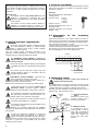
3. Pressure transducer
We strongly suggest the operator to carefully read and follow
the information contained in Danfoss Design Guide, in Danfoss
Quick Set-up, in MXV operating instructions and in these
instructions.
The pressure transducer is an analog instrument with a 4-20 mA
output signal that makes it possible to continuously read the
pressure in a system.
Symbols used:
This symbol indicates high voltage hazard. It calls
attention to components or procedures that could
represent a potential danger to the health and welfare
of the operator.
This symbol is used to call the operator’s attention to
situations of potential danger for people or for
operations that could cause damage to the product.
Features:
Standards: EN 50081-1, EN 50082-2.
Voltage: 8-28 V
Pressure range:
0-6 bar;
0-10 bar;
0-16 bar;
0-25 bar
Output: 4-20 mA
Working temperature: da 0 a +50 °C
Protection: IP 65
Hydraulic connection: G 1/4 maschio
Weigth: ~ 60 g
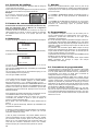
3.1. Connection
converter
2. Special warnings regarding the
inverter
We strongly suggest the operator to carefully read and
follow the information contained in Danfoss Design
Guide, in Danfoss Quick Set-up, in MXV operating
instructions and in this booklet too.
This one contains specific instructions pertaining to the
application inverter-electropump in addition to the general
information given in the above-mentioned manuals.
to
the
frequency
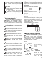
Remove the inverter box cover, which is held by 4 screws, to
obtain access to the terminals. Connect the pressure transducer
to the terminal blocks X101 as indicated in the drawing below.
Use a screened small cable 2 x 0, 5 mm2.
Terminals 3 and 6 can receive a remote input (ex. from a float),
otherwise the bridge between them must be left.
At the end the cover and the cable entries must be fitted.
See also paragraphs 2 and 4 in the Quick Set-up.
1
2
3
4
X101
5 6
7
8
The INVERTER should NEVER be opened or
tampered with and guards that come with it should
never be removed.
4.93.368
2
The inverter must be fitted with voltage surge and
overload protection devices, in accordance with the
prevailing safety standards.
If a differential protection is necessary, install a type A
differential switch, protected against untimely
activation and with threshold of intervention of 300 mA.
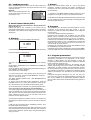
4. Diaphragm vessel
A diaphragm pressure vessel must always be
installed on the pump outlet.
For variable speed sets, vessels are used to make the pressure
more stable and to accumulate some water to avoid pumps
operation with small consumption or leakage in the system.
Generally are used diaphragm vessels with capacity of 10% of
maximum flow, with a minimum of 20 lt.
1 = 20-24 liter membrane
vessel.
Necessary to grant a good
pressure reading and a
20-24 liter
membrane vessel proper pump operation.
additional
vessel
All the power terminals and other terminals must be
inaccessible after installation is completed.
2
The maximum output frequency must be suitable for the
type of pump to control.
Operating at a frequency higher than the allowable
frequency can cause higher current absorption and damage to
the apparatus.
6
4
Pressure transducer
terminal board
The connections of the alarms can distribute power even
when the inverter is turned off. Ensure that there is no
residual voltage on the terminals of the alarms.
FC motors are designed for application on pumps that
normally pump water and therefore at a density of
1kg/dm3 and a maximum kinematic viscosity of 20 mm2/s.
Liquids that have a greater density or viscosity cause a greater
absorption of power that is incompatible with the correct
functioning of the inverter.
1
3
The inverter must be installed, adjusted and maintained
by qualified personnel who understand the risks intrinsic
to it.
ELECTRICAL SHOCK HAZARD! Disconnect the
mains supply before accessing the inverter.
The residual voltage inside the inverter, remains at a
dangerous level even after disconnection.
Wait at least 4 minutes before accessing any electrical parts.
9
1
pressure
gauge
4.93.369
variable
speed pump
pressure
transducer
2 = additional vessel.
It is required to store a
certain quantity of water to
ball valve
feed little consumptions
without having the pump to
start (not required for
pumps with small motor
powers).