1
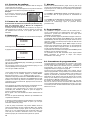
4.1. Loading pressure
7. Alarms
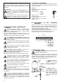
Before installation check the status of the air cushion load in the
vessel. Air preloaded pressure of the vessel must be of 2/3 of the
operating pressure.
Example:
with a 3 bar operating pressure, the
vessel should have a pressure of air
preloading of 2 bar.
Refer to the Danfoss Guide, pages 99 – 102 for the general
indications regarding warnings and alarms visualized and
managed by the LCP. Those alarms specific to the application
are the following:
7.1 ALARM 2: LIVE ZERO ERROR visualized when there is an
irregularity in the signal coming from the pressure transducer.
7.2 ALARM 38: NO WATER visualized when the pump is running
dry. The software is set to make 3 attempts at re-starting after the
first alarm (parameter 405).
5. Local Control Panel (LCP)
Before using the LCP read instruction in Design Guide from
page 26 to page 32.
Connect the LCP to the connector on the inverter via the
appropriate supplied cable. The LCP is also fed when connecting
the inverter to the electrical power supply and the pump can be
switched on.
6. Starting
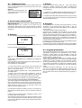
a) When switching on, the LCP displays the following:
FEED-BACK bar
0.000
LOCAL/STOP
0.000 (that flashes and indicates the pressure actually measured)
8. Program
The parameters set in the factory have been tested for a correct
functioning of the electrical pump with inverter. It may be
necessary to adjust them after the installation of the equipment
into the system.
If necessary, adjust the following parameters:
Parameter 428, accessible from the MENU (not the QUICK
MENU) must be increased by a few units if the inverter does not
stop the electrical pump when the flow is very low or inexistent.
Parameter 428, accessible from the MENU shows the minimum
functioning time of the FC motor. It is advisable to not reduce the
value set in the factory and it must not be set at less than 15
seconds under any circumstances.
Parameter 205, accessible also from the QUICK MENU permits
the establishing of the pressure set point.
Parameters 207 and 208, accessible also from the QUICK MENU
permit the adjustment of the acceleration and braking ramp times.
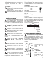
b) Press the DISPLAY/STATUS key
0.0Hz
0.00A
0000W
0.000
LOCAL/STOP
The LCP is programmed in the factory to supply the following
data:
On the first line: FREQUENCY (Hz). CURRENT (A). POWER (W)
(initially all at 0).
On the second line: the pressure read by the transducer [bar] (>0
if the hydraulic circuit is in pressure).
On the fourth line: LOCAL/STOP
c) To check the set point of the pressure set by the factory and
change it if necessary, press the QUICK MENU key. Press the ““key or “+” key up to 5 of 10.
The display indicates parameter 205 – MAX REFERENCE with
the relative value.
To enter in the function that permits modifications, press the
CHANGE DATA key. To confirm the modification, press the OK
key. When finished, press the DISPLAY/STATUS key again.
8.1. Program parameters
The software that manages the functions of the inverter has been
appropriately designed for the applications on the pumps,
therefore it differs slightly from the standard to which the
programming parameters are described in detail in the Danfoss
Design Guide from pages 36 to 81.
The list with all parameters utilised by the software with the
relative programming value can be found in the attached table
entitled MCT 10 Set-up Software. This list particularly contains
the Group parameters [4]: Special functions, from ID 420 to ID
430 (excluding ID 429 that is for reading only) utilised by specific
software and therefore not described in the afore-mentioned
Guide.
Parameters having the following ID: 147, 403, 404, 406, 407,
from 515 to 571 and 635 are instead described in the Guide, but
they are not available in the pump-based application, therefore
they are neither in the above-mentioned table nor they appear on
the LCP.
d) The electrical pump is switched on by pressing START button.
If it is necessary to stop the pump, press STOP button.
The inverter brings the electrical pump to the correct R.P.M. to
reach and maintain the set point of the set pressure (parameter
205). On lines 1 and 2 the values mentioned in point b) are read.
When switching the pump on for the first time, wait for the
hydraulic circuit to dispel all the air.
e) Check that the pressure reached is correct. If not, modify it by
repeating the procedure at point c) (it is not necessary to stop the
pump).
f) With the pump functioning at the established pressure, close
the inflow shutter to zero the flow.
Check that the inverter stops the pump after a short period. In this
case, the electrical pump can function without the LCP connected
to the inverter. Otherwise, stop the pump using the STOP button
and go to point 8.
7