1
+0500053ML - rel. 1.2 del 17.01.2013
MX(1,3)0****** - MPXPRO Collegamenti elettrici e di rete/MPXPRO Wiring and network connections/Connexions électriques et de réseau/Elektro- und Netzwerkanschlüsse
1
2
3
L
N
NO NC
4
(
5
C
6
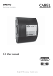
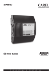
This technical leaflet describes the MPXPRO family, highlighting the electrical connections for the main
board, the options and the accessories. All the components are described in the full-optional versions.
Consequently, this represents the maximum possible application of the MPXPRO. Other simpler possibilities depend on the specific product codes and applications.
CAREL CODE
RS485 RELAY MAP
&
(see the wiring
RTC diagram)
MODEL
MX(1,3)0M00**0
MX(1,3)0S00**0
MX(1,3)0S10**0
MX30M21**0
MX30S21**0
MX30S31**0
MX30M25**0
Master
Slave
Slave
Master
Slave
Slave
Master
MX30S25**0
Slave
MX30M24**0
Master
MX30S24**0
Slave
-
-
PROBES
PWM
EXPANSION BOARD
outputs (installed on the main board)
2
2
2
2
R1,R2,R3,R4,R5
R1,R2,R3,R4,R5
R1,R3;R5
R1,R2,R3,R4,R5
R1,R2,R3,R4,R5
R1,R3,R5
R1,R2,R3,R4,R5
NTC
NTC
NTC
NTC/PTC/PT1000
NTC/PTC/PT1000
NTC/PTC/PT1000
NTC/PTC/PT1000
R1,R2,R3,R4,R5
NTC/PTC/PT1000 2
R1,R2,R3,R4,R5
NTC/PTC/PT1000 2
R1,R2,R3,R4,R5
NTC/PTC/PT1000 2
CAREL E2V DRIVER +0 to10
Vdc output
CAREL E2V DRIVER +0 to10
Vdc output
PWM DRIVER +0 to 10 Vdc
output
PWM DRIVER +0 to 10 Vdc
output
9
R2
R3
115-230 V
MX(1,3)0***** AC
200 mA max
R1
Models:
8
NO NC
R1
General description
7
NO C
( (
( (
10 11 12 13
C
NO
NO NC
R3
R4
10 (2) A N.O.
R5
6 (4) A N.O.
S3
S4/
GND DI1
37 36 35 34 33
6 (4) A N.O.
6 (4) A N.C.
T.U.I. M.S.N.
VL Tx/Rx
Tx/Rx
DI5 GND
32 31 30 29 28
27 26 25 24
23
MCHRTF
LOAD 2
PWM modulating fans
SSR1
LOAD 1
Trim heater
21
Only “Master units”
to be connected
on RS485
DEFROST TEMPERATURE
PROBE (Sd)
AIR ON TEMPERATURE
PROBE (Sr)
SUPERHEATED GAS
PROBE (tGS)
SATURASTED EVAPORATION
PRESSURE/TEMPERATURE
PROBE (PEu/tEu)
AIR OFF TEMPERATURE
PROBE (Sm)
Slave 1
Slave 2
Slave 3
Slave 4
S5/ S6/
S7/
DI2 DI3 GND DI4 5Vdc
37 36 35 34 33
32 31 30 29 28
S2
S3
IR*U*
tLAN
IR*X*
Connection:
WICHTIGE HINWEISE: Das CAREL Produkt ist ein Produkt nach dem neuesten Stand der Technik, dessen Betriebsanleitungen in den
dem Produkt beiliegenden technischen Spezifikationen enthalten sind oder - auch vor dem Kauf - von der Internetseite www.carel.
com heruntergeladen werden können. Der Kunde (Hersteller, Planer oder Installateur der Endausstattung) übernimmt jede Haftung
AC 230 V
und Risiken in Bezug auf die Produktkonfiguration zur Erzielung der bei der Installation und/oder spezifischen Endausstattung vorge50 Hz
sehenen Resultate. Die Unterlassung dieser Phase, die im Benutzerhandbuch verlangt/angegeben ist, kann zu Funktionsstörungen der
Endprodukte führen, für welche CAREL nicht verantwortlich gemacht werden kann. Der Endkunde darf das Produkt nur auf die in den
Produktspezifikationen beschriebenen Weisen verwenden. Die Haftung CARELS für die eigenen Produkte ist von den allgemeinen CAREL
Vertragsbedingungen (siehe Internetseite www.carel.com) und/oder durch spezifische Vereinbarungen mit den Kunden geregelt.
NTC /PTC/Pt1000
VL (25) GND (26)
T.U.I.
Tx/Rx (24)
PWM
ac
POWER SUPPLY N
115-230 Vac L
25 VA max
+
N L
L
(see the technical
leaflets +050000135)
PWM
dc
PWM valve
115 Vdc RMS-230 Vdc RMS
20 W max 5 W min
–
60 61 62 63 64 65
0 T5 0
N PWM AC PWM DC
N
+
L
-
MX3OPPWM*
4 to 20 mA
0 to 10 Vdc
connection with
AC 24 V
S7/
GND DI4
30
29
S7/
GND DI4
30
29
S7/
GND DI4
30
29
28
29
30
31
5Vdc
S7/D14
GND
S6/D13
color
Green
White
White
4.2
9.3
17.3
-15
-15
0
60
135
250
SPKT0033R0
SPKT00B6R0
SPKT0011S0 (*)
SPKT0041S0 (*)
SPKT0031S0 (*)
SPKT00B1S0 (*)
SPKT00G1S0 (*)
0.0
0.0
-1
0
0
0
0
34.5
45.0
9.3
17.3
34.5
45.0
60.0
0
0
-15
0
0
0
0
500
650
135
250
500
650
870
GND
2CP5-52
2CP5-46
52CP36-01
2CP5-66
2CP5-47
2CP50-1
-
(*) =installation without capillary tubing possible
The input of the load 0 to 10 Vdc must
feature reinforced insulation with
reference to its internal power supply
Black
Analogic 0 to10 Vdc
CAREL electronic pressure probe
Range
Range
CAREL code (barg)
Probe ref.
(psig)
min max min max
-1.0
-1.0
0.0
68 67 66
S6/
S7/
DI3 GND DI4 5Vdc
31 30
29
28
Black
White
Green
White
SPKT0053R0
SPKT0013R0
SPKT0043R0
10
GND Vdc
0 to10 Vdc
Connect with CAREL cable
SPKC003310 or SPKC005310
terminal
Analogic
output only for
MX2OPPWM0*
Use only one
pressure probe
Pressure probe connection:
+G
AVERTISSEMENTS IMPORTANTS: Le produit CAREL est un produit avancé dont le fonctionnement est spécifié dans la documentation
technique fournie avec le produit ou téléchargeable, même avant l’achat, du site Internet www.carel.com. Le client (constructeur,
concepteur ou installateur de l’équipement final) assume toutes les responsabilités et risques quant à la configuration du produit pour
l’obtention des résultats prévus quant à l’installation et/ou à l’équipement final spécifique. L’absence de cette phase d’étude qui est
requise/indiquée dans le manuel d’instructions peut provoquer des dysfonctionnements des produits finals dont CAREL ne pourra en
aucun cas être jugée responsable. Le client final doit utiliser le produit exclusivement selon les modes décrits dans la documentation
correspondant au produit. La responsabilité de CAREL en ce qui concerne son produit est réglée par les conditions générales de contrat
CAREL publiées sur le site www.carel.com et/ou par des accords spécifiques stipulés avec les clients.
Power Supply
GND
Rx/Tx
GND
DC/AC output
Fuse 0.25 AT
NTC
out
NTC
out
M
-G0
out
H
IMPORTANT WARNINGS: The CAREL product is a state-of-the-art device, whose operation is specified in the technical documentation
supplied with the product or can be downloaded, even prior to purchase, from the website www.carel.com. The customer (manufacturer, developer or installer of the final equipment) accepts all liability and risk relating to the configuration of the product in order to reach
the expected results in relation to the specific installation and/or equipment. The failure to complete such phase, which is required/
indicated in the user manual, may cause the final product to malfunction; CAREL accepts no liability in such cases. The customer must
use the product only in the manner described in the documentation relating to the product.The liability of CAREL in relation to its
products is specified in the CAREL general contract conditions, available on the website www.carel.com and/or by specific agreements
with customers.
remote infrared
IRTRMPX000
Analogic input Ratiometric
0 to 10 Vdc
(external power pressure
probe 0 to 5 Vdc
supply)
AVVERTENZE IMPORTANTI: Il prodotto CAREL è un prodotto avanzato, il cui funzionamento è specificato nella documentazione tecnica
fornita col prodotto o scaricabile, anche anteriormente all’acquisto, dal sito internet www.carel.com. Il cliente (costruttore, progettista o
installatoredell’equipaggiamento finale) si assume ogni responsabilità e rischio in relazione alla fase di configurazione del prodotto per il
raggiungimento dei risultati previsti in relazione all’installazione e/o equipaggiamento finale specifico. La mancanza di tale fase di studio,
la quale è richiesta/indicata nel manuale d’uso, può generare malfunzionamenti nei prodotti finali di cui CAREL non potrà essere ritenuta
responsabile. Il cliente finale deve usare il prodotto solo nelle modalità descritte nella documentazione relativa al prodotto stesso. La
responsabilità di CAREL in relazione al proprio prodotto è regolata dalle condizioni generali di contratto CAREL editate nel sito www.
carel.com e/o da specifici accordi con i clienti.
Humidity probe Analogic input
DPWC111000
4 to 20 mA
(external power
supply)
Entsorgung des Produktes: Das Gerät (oder Produkt) muss im Mülltrennungsverfahren in Übereinstimmung mit den örtlichen Entsorgungsnormen entsorgt werden.
Earth
MX3OPA100*
OR
probe ref.
Analogic
output
probe ref.
L < 10m
AWG22
L < 30m
AWG20
L < 50m
AWG18
PWM Driver
PWM valve
115-230 Vac
20 VA max 5 VA min
AUX
AUX
1 2 3
Élimination du produit: L’équipement (ou le produit) doit faire l’objet d’un ramassage particulier en conformité avec les normes en
vigueur locales en matièred’élimination des déchets
5
For further information, please refere to the “EEV system guide”
(code +030220810) available in the web site www.carel.com, in the
literature section.
Slave 5
Terminal/user interface: max. cable lenght 100 m with a section not less then AWG20
Power
Supply
Rx/Tx
Gnd
Disposal of the product: The appliance (or the product) must be disposed of separately in compliance with the local standards in force
on waste disposal.
S4/
GND DI1
S1
75
Shield
84
83
82
81
80
Unique correct
connection view
(no other possible
connections).
E2VCON* not suitable
for refrigeration
application.
Shield
RATIOMETRIC
4
20
Master/Slave network: max. cable lenght 100 m with a section not less then AWG20
NTC
2
3
Valve cable lenght without solenoid
Shield
NTC
YE WH
1
To be used only with
control switch off
(no Power Supply)
Supervisor
RS485
NTC
GR BR
MXOPZKEYA0/IROPZKEYA0 (firmware 1.x)
Default connection:
NTC
connection cable
CAREL E2V
84 83 82 81 80
Green
Brown/Red
Yellow/Black
White
Shield
(only for models MX(1,3)0S*****)
Possible connection:
Smaltimento del prodotto: L’apparecchiatura (o il prodotto) deve essere oggetto di raccolta separata in conformità alle vigenti normative locali in materia di smaltimento
CAREL E2VCABS*
MX3OP48500
GND Tx/Rx+ Tx/Rx-
22
MX3OPST(H,U)*
20 mA max totally
MX3OP485**
PROG. KEY
S5/ S6/
S7/
DI2 DI3 GND DI4 5Vdc
Tight screw and nut after
installing connector/cable and E2V.
CLOCK
and
SERIAL INT.
Tab. 1
Warning:
• The board must not be installed on surfaces that exceed 70 °C (50 °C ambient) and 80 °C (60 °C ambient);
• Use with an external disconnect switch positioned near the appliance that is compliant with the
IEC60947-1 and IEC60947-3 standards;
• Use cables with a temperature rating of 90 °C, if the temperature of the terminals exceeds 85 °C uses a
cable with a temperature rating of 105 °C;
• The connection cables must guarantee insulation up to 90 °C and if necessary up to 105 °C, when the
temperature of the relay terminals exceeds 85 °C;
• If the appliance is used in a way that is not specified by the manufacturer, the guaranteed protection
of the appliance may be compromised;
• If the current is higher than 6 A in R1, R2, R3, R4, R5, use only cables with a section of 2.5 mm2 (14 AVG);
• The board must not be accessible to people without warrant of installing.
R=470 Ω
Mounted on
MX(1,3)0S*****
-10T50
S2
0 to10 Vdc
73 74 Analogic
10
Vdc GND output only for
MX3OPST(H,U)0*
The contemporary operation of both outputs
is not granted with any actuator.
Please refer to the technical features.
R5
Maximum currents with removable vertical connectors cod. MX(1,3)0***(C,I,O)**.
For more details, please refer to the technical leaflets.
S1
C
Expansion board:
- E 2V driver MX3OPSTP**
- PWM driver MX3OPPWM**
- 0 to10 Vdc Analog output MX3OPA10**
10 (10) A N.O.
GND
The input of the load 0 to 10 Vdc must
feature reinforced insulation with
reference to its internal power supply
E2V Driver
14 15 16
C
R4
R2
6 (4) A N.O.
EN60730-1 6 (4) A N.C.
AUX2
PWM2 PWM1 12 V
(
AUX1
19 18 17
AUX3
do not connect to
any “GND” Terminal
N
L
Cable Lenght
Power Supply
AC 115-230 V
200 mA max
L N AUX4
10
GND Vdc
42 41 40
0 to10 Vdc
GND
The input of the load 0 to 10 Vdc must
feature reinforced insulation with
reference to its internal power supply
Use
PWMac or PWMdc
valves alternatively
MX(1,3)0* board technical specifications
Caratteristiche tecniche scheda MX(1,3)0*
Modello
Tensione
Potenza
MXxxxx(0,1,2,4) 230 V~ , 50/60 Hz
11,5 VA, 50 mA~ max
Alimentazione
(E,H)xx
MXxxxx(3,5,6)Hxx 115 V~... 230 V~,
23 VA, 115 V~ (200 mA~ max), 230 V~
50/60Hz
(100 mA~ max)
rinforzato
isolamento rispetto Isolamento 3 mm in aria, 8 superficiali
alla bassissima tensione 3750 V isolamento
garantito MXxxxxx(E,A,H)xx
dall’
isolamento rispetto principale
1,5 mm in aria, 4 superficiali
alimentazione
alle uscite relè
1250 V isolamento
S1, S2 e S3
NTC (MXxxxx0xxx) o NTC, PTC, PT1000 e NTC L243 (MXxxxx(1,2,3,4,5,6,7,8)xxx)
S4/DI1, S5/DI2
NTC (MXxxxx0xxx) o NTC, PTC, PT1000 e NTC L243 (MXxxxx(1,2,3,4,5,6,7,8)xxx)
contatto pulito, resistenza contatto < 10 ohm, corrente di chiusura 6 mA
S6/DI3
NTC (MXxxxx0xxx) o NTC, PTC, PT1000 e NTC L243 (MXxxxx(1,2,3,4,5,6,7,8)xxx)
0...5 V raziometrico (MXxxxxxxxx)
contatto pulito, resistenza contatto < 10 ohm, corrente di chiusura 6 mA
Ingressi
S7/DI4
NTC (MXxxxx0xxx) o NTC, PTC, PT1000 e NTC L243 (MXxxxx(1,2,3,4,5,6,7,8)xxx)
0...5 V raziometrico (MXxxxxxxxx), 4...20 mA, 0...10 V (MXxxxx(1,2,3,4,5,6,7,8)xxx)
contatto pulito, resistenza contatto < 10 Ω, corrente di chiusura 6 mA
DI5
contatto pulito, resistenza contatto < 10 Ω, corrente di chiusura 6 mA
Distanza massima sonde ed ingressi digitali minore di 10 mt. Nota: nell’installazione si raccomanda
di tenere separati i collegamenti di alim. e dei carichi dai cavi delle sonde, ingressi digitali, display
ripetitore e supervisore.
10 kΩ a 25 °C, range da –50 °C a +90 °C
1 °C nel range da –50 °C a +50 °C; 3 °C nel range da
NTC std. CAREL
errore di misura
+50 °C a +90 °C
985 Ω a 25°C, range da -50 °C a 150 °C
PTC std. CAREL 2 °C nel range da –50 °C a +50 °C; 4 °C nel range da
(modello specifico) errore di misura
+50 °C a +150 °C
1000 Ω a 0 °C, range da –50 °C a +90 °C
1 °C nel range da –50 °C a +50 °C; 3 °C nel range da
Pt 1000
errore di misura
Tipo sonda
+50 °C a +90 °C
2000 Ω a 0 °C, range da -50 °C a 90 °C
NTC L243
errore di misura
2 °C nel range da –50 °C a +25 °C
risoluzione 0,1 % fs
0...5 V raziometrico
errore di misura
2 % fs massimo; 1 % tipico
risoluzione 0,5 % fs
4...20 mA
errore di misura
8 % fs massimo; 7 % tipico
risoluzione 0,1 % fs
0...10 V
errore di misura
9 % fs massimo; 8 % tipico
La gamma MPXPRO equipaggiata con sonda NTC CAREL modello: NTC015WF00, NTC030HF01
e NTC015HP00, risulta conforme alla norma UNI EN 13485 relativa ai termomentri per la misurazione della temperatura dell’aria, per applicazioni su unità di conservazione e di distribuzione di
EN13485:2003
alimenti refrigerati, congelati e dei gelati. Designazione dello strumento: EN13485, aria, S, A, 1,
-50T90°C. La sonda NTC standard CAREL è identificabile per il codice stampato laser nei modelli
“WF”, “HF” o per la sigla “103AT-11” nei modelli “HP” entrambi visibili nella parte del sensore.
EN60730-1
250V~
cicli di manovra
6 (4) A su N.O.
R1, R5
6 (4) A su N.C.
100000
R4
2 (2) A su C.O.
R3
10 (2) A su N.O.
100000
R2
10 (10) A su N.O.
100000
relè
Uscite Relè
UL (only MX30*)
250V~
cicli di manovra
6A res 240Vac N.O. / N.C.
1/2Hp 240Vac N.O.
30000
1/6 Hp 120Vac N.O.
10A res 240Vac
30000
10A res 1Hp 240/120 Vac N.O.
6000
rinforzato
3 mm in aria, 8 superficiali
3750V isolamento
principale
1,5 mm in aria, 4 superficiali
1250 V isolamento
Tensione d’uscita, massima corrente erogabile (non isolata
rispetto alla massa della scheda)
12 Vdc, 20 mA max per ciascuna uscita PWM
Isolamento rispetto la bassissima tensione
Isolamento tra le uscite relè indipendenti
Uscite analogiche Modello
PWM 1, 2
MXxxx(2, 3)xxxx
Tipo connessione
modello
Connessioni
Dimensioni
Sezioni
alimentazione
vite 180°
relè
Corrente
massima
MXxxxxxx(A,G,M)x vite 180°
vite 180°
12 A
estraibile
MXxxxxxx(C,I,O)x
estraibile 180° estraibile 180°i
180°
Il corretto dimensionamento dei cavi di alimentaz. e di collegam. tra lo strumento e i carichi è a cura
dell’istallatore.
base con coperchio
solo base
solo scheda
Orologio
Temperatura di funzionamento
109 (base) x 137 (altezza) x 81 (profondità) mm
105 (base) x 111 (altezza) x 65 (profondità) mm
100 (base) x 108 (altezza) x 55 (profondità) mm
errore a 25°C
errore nel range di temp. –10T60 °C
invecchiamento
Tempo di scarica
Tempo di ricarica
MXxxxxxx(A,B,C,G,I)x
MXxxxxxx(M,N,O)x
Grado di protezione
Umidità di funzionamento
Temperatura di immagazzinamento
Umidità di immagazzinamento
Grado di inquinamento ambientale
PTI dei materiali di isolamento
Periodo delle sollecitazioni elettriche delle parti isolanti
Categoria di resistenza al fuoco
Classe di protezione contro le sovratensione
Tipo di azione e disconnessione
Costruzione del dispositivo di comando
Classificazione secondo la protezione contro le scosse
elettriche
Dispositivo destinato ad essere tenuto in mano o
incorporato in apparecchiatura destinata ad essere
tenuta in mano
Classe e struttura del software
Display principale e secondario
Massima distanza tra controllo e display
Collegamento LAN locale
Model
Voltage
Power
MXxxxx(0,1,2,4) 230 V~ , 50/60 Hz
11.5 VA, 50 mA~ max
(E,H)xx
Power supply
115 V~... 230 V~,
23 VA, 115 V~ (200 mA~ max), 230 V~
MXxxxx(3,5,6)Hxx
50/60Hz
(100 mA~ max)
insulation from very reinforced
3 mm in air, 8 mm on surface
Insulation low voltage parts
3750 V insulation
guaranteed from MXxxxxx(E,A,H)xx
insulation from relay primary
the power supply
1,5 mm in air, 4 mm on surface
outputs
1250 V insulation
S1, S2 and S3
NTC (MXxxxx0xxx) or NTC, PTC, PT1000 & NTC L243 (MXxxxx(1,2,3,4,5,6,7,8)xxx)
S4/DI1, S5/DI2
NTC (MXxxxx0xxx) or NTC, PTC, PT1000 & NTC L243 (MXxxxx(1,2,3,4,5,6,7,8)xxx)
voltage-free contact, contact resistance < 10 ohm, closing current 6 mA
S6/DI3
NTC (MXxxxx0xxx) or NTC, PTC, PT1000 & NTC L243 (MXxxxx(1,2,3,4,5,6,7,8)xxx)
0 to 5 V ratiometric (MXxxxxxxxx)
voltage-free contact, contact resistance < 10 ohm, closing current 6 mA
Inputs
S7/DI4
NTC (MXxxxx0xxx) or NTC, PTC, PT1000 & NTC L243 (MXxxxx(1,2,3,4,5,6,7,8)xxx)
0 to 5V ratiometric (MXxxxxxxxx), 4 to 20 mA, 0 to 10 V (MXxxxx(1,2,3,4,5,6,7,8)xxx)
voltage-free contact, contact resistance < 10 Ω, closing current 6 mA
DI5
voltage-free contact, contact resistance < 10 Ω, closing current 6 mA
Maximum distance of probes and digital inputs less than 10 m. Note: the power and load connections
should be kept separate from the connections to the probe cables, digital inputs, repeater display
and supervisor.
10 kΩ at 25 °C, range from –50 °C to +90 °C
1 °C in range from –50 °C to +50 °C; 3 °C in range from
Std. CAREL NTC
measurement error
+50 °C to +90 °C
985 Ω at 25°C, range from –50 °C to 150 °C
Std. CAREL PTC
2 °C in range from –50 °C to +50 °C; 4 °C in range from
(specific model) measurement error
+50 °C to +150 °C
1000 Ω at 0 °C, range from –50 °C to +90 °C
1 °C in range from –50 °C to +50 °C; 3 °C in range from
Pt 1000
measurement error
Type of probe
+50 °C to +90 °C
2000 Ω at 0 °C, range from –50 °C to 90 °C
NTC L243
measurement error 2 °C in range from –50 °C to +25 °C
resolution 0.1 % fs
0 to 5 V ratiometric
measurement error 2 % fs maximum; 1 % typical
resolution 0.5 % fs
4 to 20 mA
measurement error 8 % fs maximum; 7 % typical
resolution 0.1 % fs
0 to 10 V
measurement error: 9 % fs maximum; 8 % typical
The MPXPRO range fitted with the standard CAREL NTC sensor, models: NTC015WF00,
NTC030HF01 and NTC015HP00, is compliant with standard EN 13485 on thermometers for measuring the air and product temperature for the transport, storage and distribution of chilled, froEN13485:2003
zen, deep-frozen/quick-frozen food and ice cream. Designation of the instrument: EN13485, air, S,
A, 1, -50T90°C. The standard Carel NTC sensor is identifiable by the printed laser code on “WF” or
“HF” models, or the code “103AT-11” on “HP” models, both visible on the sensor part.
EN60730-1
relay
Relay outputs
± 10 ppm (±5,3min/anno)
- 50 ppm (-27min/anno)
< ±5 ppm (±2,7min/anno)
6 mesi tipico (8 mesi massimo)
5 ore tipico (< di 8 ore massimo)
-10T60 °C
-10T50 °C
IP00
<90% U.R. non condensante
-20T70 °C
<90% U.R. non condensante
grado 3
circuiti stampati 250, plastica e materiali isolanti 175
Lungo
categoria D (EN60730-1)
categoria III con l’ausilio di dispositivi di soppressione
delle sovratensioni
contatti relè 1C (microinterruzione)
dispositivo di comando incorporato, elettronico
Classe II per mezzo di appropriata incorporazione
no
Classe A
Esterni
fino a 10m con cavo schermato AWG22 (VL, Rx-Tx, gnd)
fino a 100m con cavo schermato AWG20 (max un
terminale)
100 mt totali, cavo schermato AWG20 (Rx-Tx, gnd)
250V~
R3
6 (4) A on N.O.
6 (4) A on N.C.
2 (2) A on C.O.
10 (2) A on N.O.
R2
10 (10) A on N.O.
R1, R5
R4
insulation from very low voltage parts
insulation between independent relay
outputs
PWM analogue
outputs 1, 2
sonde
per cavi da 0,5
a 2,5 mm2
Caractéristiques techniques fiche MX(1,3)0*
Connections
Model
MXxxx(2, 3)xxxx
operating
cycles
100000
100000
100000
UL (only MX30*)
250V~
6A res 240Vac N.O. / N.C.
1/2Hp 240Vac N.O.
1/6 Hp 120Vac N.O.
10A res 240Vac
10A res 1Hp 240/120 Vac
N.O.
30000
6000
reinforced
3 mm in air, 8 mm on surface
3750V insulation
primary
1,5 mm in air, 4 mm on surface
1250 V insulation
Voltage output, maximum current delivered (not insulated from the
earth of the board)
12 Vdc, 20 mA max for each PWM output
Type of connection
Size
Maximum current
model
relays
power supply
probes
for cables from
MXxxxxxx(A,G,M)x screw 180° screw 180°
screw 180°
12 A
0.5 to 2.5 mm2
MXxxxxxx(C,I,O)x plug-in 180° plug-in 180° plug-in 180°
The correct sizing of the power cables and the connections between the instrument and the loads is the
installer’s responsibility.
Dimensions
base with cover
base only
board only
109 (long) x 137 (high) x 81 (wide) mm
105 (long) x 111 (high) x 65 (wide) mm
100 (long) x 108 (high) x 55 (wide) mm
Modèle
Tension
Puissance
MXxxxx(0,1,2,4) 230 V~ , 50/60 Hz 11.5 VA, 50 mA~ max
(E,H)xx
115 V~...230 V~,
23VA, 115 V~ (200 mA~ max), 230 V~
MXxxxx(3,5,6)Hxx
50/60Hz
(100 mA~ max)
isolation par rapRenforcée
port à la basse ten- 3 mm dans l’air, 8 superficiels
3750 V isolation
MXxxxxx(E,A,H)xx sion extrême
Isolation entre les principale
1,5 mm dans l’air, 4 superficiels
sorties relais
1250 V isolation
S1, S2 e S3
NTC (MXxxxx0xxx) o NTC, PTC, PT1000 et NTC L243 (MXxxxx(1,2,3,4,5,6,7,8)xxx)
Alimentation
Isolation garantie
par
l’alimentation
Entrées
Type sonde
EN13485:2003
NTC (MXxxxx0xxx) o NTC, PTC, PT1000 et NTC L243 (MXxxxx(1,2,3,4,5,6,7,8)xxx)
contact propre, résistance contact < 10 ohm, courant de fermeture 6 mA
S6/DI3
NTC (MXxxxx0xxx) o NTC, PTC, PT1000 et NTC L243 (MXxxxx(1,2,3,4,5,6,7,8)xxx)
0...5 V ratiométrique (MXxxxxxxxx)
contact propre, résistance contact < 10 ohm, courant de fermeture 6 mA
S7/DI4
NTC (MXxxxx0xxx) o NTC, PTC, PT1000 e NTC L243 (MXxxxx(1,2,3,4,5,6,7,8)xxx)
0...5 V ratiométrique MXxxxxxxxx), 4...20 mA, 0...10 V MXxxxx(1,2,3,4,5,6,7,8)xxx
contact propre, résistance contact < 10 Ω, courant de fermeture 6 mA
DI5
contact propre, résistance contact < 10 Ω, courant de fermeture 6 mA
Distance maximum sondes et entrées digitales inférieure à 10 m. Note: dans l’installation, il est recommandé de maintenir séparés les raccordements d’alim. et des charges des câbles des sondes,
entrées digitales, affichage répétiteur et superviseur.
10 kΩ à 25 °C, intervalle de –50 °C à +90 °C
1 °C intervalle de –50 °C à +50 °C; 3 °C intervalle de
NTC std. CAREL
erreur de mesure
+50 °C à +90 °C
985 Ω a 25°C, intervalle de -50 °C à 150 °C
PTC std. CAREL 2 °C intervalle de –50 °C à +50 °C; 4 °C intervalle de
(mod. spécifique) erreur de mesure
+50 °C à +150 °C
1000 Ω a 0 °C, intervalle de –50 °C à +90 °C
1 °C intervalle de –50 °C à +50 °C; 3 °C intervalle de
Pt 1000
erreur de mesure
+50 °C à +90 °C
2000 Ω a 0 °C, intervalle de -50 °C à 90 °C
NTC L243
erreur de mesure 2 °C intervalle de –50 °C à +25 °C
0...5 V ratiRésolution 0,1 % fs
ométrique
erreur de mesure 2 % fs maximum; 1 % typique
Résolution 0,5 % fs
4...20 mA
erreur de mesure 8 % fs maximum; 7 % typique
Résolution 0,1 % fs
0...10 V
erreur de mesure 9 % fs maximum; 8 % typique
La gamme MPXPRO équipée de sonde NTC CAREL modèle: NTC015WF00, NTC030HF01 et
NTC015HP00, est conforme à la norme UNI EN 13485 sur les thermomètres pour la mesure de
la température de l’air, pour applications sur unité de conservation et de distribution d’aliments
réfrigérés, congelés et des glaces. Désignation de l’instrument: EN13485, air, S, A, 1, -50T90°C. La
sonde NTC standard CAREL peut être identifiée grâce au code imprimé laser sur les modèles “WF”,
“HF” ou au sigle “103AT-11” sur les modèles “HP”, qui sont tous les deux visibles du côté du capteur.
EN60730-1
Relais
250V~
Base avec capot
Dimensions Base seule
Carte seule
Operating temperature
MXxxxxxx(A,B,C,G,I)x
MXxxxxxx(M,N,O)x
-10T60 °C
-10T50 °C
Protection
Humidité de fonctionnement
Température de stockage
Humidité de stockage
Degré de pollution environnementale
PTI des matériaux d’isolation
Période de sollicitations électriques des parties isolantes
Catégorie de résistance au feu
Classe de protection contre les surtensions
Type d’action et déconnexion
Fabrication du dispositif de commande
Classification suivant la protection contre les
décharges électriques
Dispositif destiné à être tenu en main ou
incorporé à appareils destinés à être tenus
en main
Classe et structure du software
Affichage principal et secondaire
Maximum distance between controller and display
LAN connection
CAREL INDUSTRIES HQs
Via dell’Industria, 11 - 35020 Brugine - Padova (Italy)
Tel. (+39) 0499716611 – Fax (+39) 0499716600 http://www.carel.com – e-mail: [email protected]
109 (large) x 137 (long) x 81 (haut) mm
105 (large) x 111 (long) x 65 (haut) mm
100 (large) x 108 (long) x 55 (haut) mm
erreur à 25°C
erreur dans l’intervalle de temp. –10/60 °C
vieillissement
temps de décharge
Temps de recharge
Horloge
Class A
External
Up to10 m, with shielded cable AWG22 (VL, Rx-Tx, gnd)
Up to 100 m with shielded cable AWG20 (connect one
terminal max)
100 m total, shielded cable AWG20 (Rx-Tx, gnd)
Isolierung der
Spannungsversorgung
Température de fonctionnement
Distance maximum entre contrôle et affichage
Connexion LAN local
Eingänge
Fühlertyp
EN13485:2003
Modell
Spannung
MXxxxx(0,1,2,4) 230 V~ , 50/60 Hz
(E,H)xx
MXxxxx(3,5,6) 115 V~...230 V~, 50/60Hz
Hxx
Niedrigstspannungsisolierung
MXxxxxx(E,A)xx
Relais
Relaisausgänge
R1, R5
R4
R3
R2
EN60730-1
UL (only MX30*)
250V~
Schaltzyklen
250V~
Schaltzyklen
6 (4) A auf N.O.
6A res 240Vac N.O / N.C.
6 (4) A auf N.G.
100000
1/2Hp 240Vac N.O
30000
2 (2) A auf N.O./N.G.
1/6 Hp 120Vac N.O
10 (2) A auf N.O.
100000
10A res 240Vac
30000
10 (10) A auf N.O.
100000
10A res 1Hp 240/120 Vac N.O
6000
Niedrigstspannungsisolierung
Isolierung zw. unabhängigen Relaisausgängen
Analoge PWM-Ausgänge 1, 2
Modell
MXxxx(2, 3)xxxx
Max.
Querschnitt
Strom
SpannungsModell
Relais
Fühler
versorgung
für Kabel von
Anschlüsse
12 A
MXxxxxxx(A,G,M)x Schrauben 180° Schrauben 180° Schrauben 180° 0,5 bis 2,5 mm2
MXxxxxxx(C,I,O)x
abnehmbar 180° abnehmbar 180° abnehmbar 180°
Für die korrekte Dimensionierung der Versorgungs- und Anschlusskabel zwischen Gerät und Lasten hat
der Installateur zu sorgen
Basis mit Abdeckung
Abmessungen Nur Basis
Nur Platine
MXxxxxxx(A,B,C,G,I)x
MXxxxxxx(M,N,O)x
Uhr
IP00
<90% H.R. non condensante
-20T70 °C
<90% H.R. non condensante
3
circuits imprimés 250, plastique et matériaux isolants 175
Longue
catégorie D (EN60730-1)
catégorie III
contacts relais 1C (micro interruption)
dispositif de commande incorporé, électronique
Classe II par incorporation appropriée
no
Classe A
Externes
Jusqu’à 10 m, avec câble blindé AWG22 (power supply, rx-tx,gnd)
Jusqu’à 100 m, avec câble blindé AWG20 (Connecter un seul
affichage)
100 en total, câble blindé AWG20 (Rx-Tx,gnd)
verstärkt
3 mm in Luft, 8 oberflächig
3750V Isolierung
Grundisolierung
1,5 mm in Luft, 4 oberflächig
1250 V Isolierung
Ausgangsspannung, max. lieferbarer Strom (nicht zur Erde
der Platine isoliert)
12 Vdc, 20 mA max. für jeden PWM-Ausgang
Anschlusstyp
± 10 ppm (±5,3min/an)
- 50 ppm (-27min/an)
< ±5 ppm (±2,7min/an)
6 mois typique (8 mois maximum)
5 heures typique (< 8 heures maximum)
-10T60 °C
-10T50 °C
Leistung
11.5 VA, 50 mA~ max
23VA, 115 V~ (200 mA~ max), 230 V~
(100 mA~ max)
verstärkt
3 mm in Luft, 8 oberflächig
3750 V Isolierung
Grundisolierung
Relaisausgangsisolierung 1,5 mm in Luft, 4 oberflächig
1250 V Isolierung
S1, S2 und S3 NTC (MXxxxx0xxx) oder NTC, PTC, PT1000 und NTC L243 (MXxxxx(1,2,3,4,5,6,7,8)xxx)
S4/DI1, S5/DI2 NTC (MXxxxx0xxx) oder NTC, PTC, PT1000 und NTC L243 (MXxxxx(1,2,3,4,5,6,7,8)xxx)
Potentialfreier Kontakt; Kontaktwiderstand < 10 Ohm, Schließungsstrom 6 mA
S6/DI3
NTC (MXxxxx0xxx) oder NTC, PTC, PT1000 und NTC L243 (MXxxxx(1,2,3,4,5,6,7,8)xxx)
0...5 V ratiometrisch (MXxxxxxxxx)
Potentialfreier Kontakt; Kontaktwiderstand < 10 Ohm, Schließungsstrom 6 mA
S7/DI4
NTC (MXxxxx0xxx) oder NTC, PTC, PT1000 und NTC L243 (MXxxxx(1,2,3,4,5,6,7,8)xxx)
0...5V ratiometrisch (MXxxxxxxxx), 4...20 mA, 0...10 V (MXxxxx(1,2,3,4,5,6,7,8)xxx)
Potentialfreier Kontakt; Kontaktwiderstand < 10 Ω, Schließungsstrom 6 mA
DI5
Potentialfreier Kontakt; Kontaktwiderstand < 10 Ω, Schließungsstrom 6 mA
Max. Abstand zwischen Fühlern und digitalen Eingängen unter 10 m. N.B.: Bei der Installation müssen
die Spannungsversorgungs- und Lastanschlüsse von den Kabeln der Fühler, digitalen Eingänge, des
Repeaterdisplays und Überwachungsgerätes getrennt gehalten werden.
10 kΩ bei 25 °C, Messbereich von –50 °C bis +90 °C
1 °C von –50 °C bis +50 °C; 3 °C von
NTC Std. CAREL
Messfehler
+50 °C bis +90 °C
985 Ω bei 25°C, Messbereich von -50 °C bis 150 °C
PTC Std. CAREL 2 °C von –50 °C bis +50 °C; 4 °C von
(spezif. Modell) Messfehler
+50 °C bis +150 °C
1000 Ω bei 0 °C, Messbereich von –50 °C bis +90 °C
1 °C von –50 °C bis +50 °C; 3 °C von
Pt 1000
Messfehler
+50 °C bis +90 °C
2000 Ω bei 0 °C, Messbereich von -50 °C bis 90 °C
NTC L243
Messfehler
2 °C von –50 °C bis +25 °C
Auflösung 0,1 % fs
0...5 V ratiom.
Messfehler
2 % fs max.; 1 % typisch
Auflösung 0,5 % fs
4...20 mA
Messfehler
8 % fs max.; 7 % typisch
Auflösung 0,1 % fs
0...10 V
Messfehler
9 % fs max.; 8 % typisch
Die Produktserie MPXPRO mit dem NTC-Fühler von CAREL, Modell: NTC015WF00, NTC030HF01
und NTC015HP00 entspricht der UNI EN 13485-Norm über die Thermometer zur Lufttemperaturmessung für Anwendungen in Konservierungs- und Verteilungsgeräten von gekühlten und
tiefgekühlten Lebensmitteln sowie Speiseeis. Bezeichnung des Gerätes: EN13485, Luft, S, A, 1,
-50T90°C. Der Standard-NTC-Fühler von CAREL kann anhand des lasergedruckten Codes auf den
Modellen “WF”, “HF” oder durch die Aufschrift “103AT-11” auf den Modellen “HP” auf dem Fühlerteil
identifiziert werden.
Cycles de
manœuvre
Type connexion
Sections
Courant Max.
modèle
Relais
alimentation
sondes
pour câbles de
MXxxxxxx(A,G,M)x vis 180°
vis 180°
vis 180°
12 A
Connexions
0,5 à 2,5 mm2
MXxxxxxx(C,I,O)x amovible 180° amovible 180° amovible 180°
L’installateur est responsable du bon dimensionnement des câbles d’alim. et de connexion entre
l’instrument et les charges.
± 10 ppm (±5.3min/year)
- 50 ppm (-27min/year)
< ±5 ppm (±2.7min/year)
6 months typical (8 months max.)
5 hours typical (< di 8 hours max.)
no
UL (only MX30*)
250V~
R1, R5
R4
error at 25°C
error in temp. range –10T60 °C
ageing
Discharge time
Recharge time
IP00
<90% rH non-condensing
-20T70 °C
<90% rH non-condensing
degree 3
printed circuits 250, plastic and insulating materials 175
Long
category D (EN60730-1)
category III with overvoltage suppression devices
1C relay con (microinterruption)
integrated electronic control device
Class II when suitably integrated
Cycles de
manœuvre
6 (4) A su N.O.
6A res 240Vac N.O. / N.C.
6 (4) A su N.C.
100000
1/2Hp 240Vac N.O.
30000
2 (2) A su C.O.
1/6 Hp 120Vac N.O.
R3
10 (2) A su N.O.
100000
10A res 240Vac
30000
R2
10 (10) A su N.O.
100000
10A res 1Hp 240/120 Vac N.O
6000
renforcée
isolation par rapport à la basse
3 mm dans l’air, 8 superficiels
tension extrême
3750V isolation
principale
Isolation entre les sorties relais
1,5 mm dans l’air, 4 superficiels
indépendantes
1250 V isolation
Type
Tension de sortie, courant maximum (non isolé par rapport a la masse
Sortie analogiques
de la carte)
PWM 1, 2
MXxxx(2, 3)xxxx 12 Vdc, 20 mA max pour chaque PWM sortie
Sortie relais
Clock
Index of protection
Operating humidity
Storage temperature
Storage humidity
Environmental pollution
PTI of the insulating material
Period of stress across the insulating parts
Category of resistance to fire
Class of protection against voltage surges
Type of action and disconnection
Construction of the control device
Classification according to protection against electric shock
Device designed to he hand-held or integrated into equipment designed to be hand-held
Software class and structure
Main and secondary display
Spannungsversorgung
S4/DI1, S5/DI2
operating
cycles
30000
Technische Daten der MX(1,3)0*-Platine
Fehler bei 25 °C
Fehler im Temperaturbereich –10T60 °C
Alterung
Entladezeit
Aufladezeit
Betriebstemperatur
Schutzart
Betriebsfeuchte
Lagerungstemperatur
Lagerungsfeuchte
Umweltbelastungsgrad
PTI der Isoliermaterialien
Isolation gegen elektrische Beanspruchung
Brandschutzkategorie
Überspannungsschutz
Art der Schaltung
Bau der Steuervorrichtung
Schutzklasse gegen Stromschläge
Handgerät oder eingebaut in Handgerät
Softwareklasse und -struktur
Haupt- und Zusatzdisplay
Max. Abstand zw. Steuerung und Display
LAN-Verbindung
109 (Länge) x 137 (Höhe) x 81 (Breite) mm
105 (Länge) x 111 (Höhe) x 65 (Breite) mm
100 (Länge) x 108 (Höhe) x 55 (Breite) mm
MXxxxxxx(A,B,C,G,I)x
MXxxxxxx(M,N,O)x
± 10 ppm (±5,3 Min./Jahr)
- 50 ppm (-27 Min./Jahr)
< ±5 ppm (±2,7 Min./Jahr)
6 Monate typisch (8 Monate max.)
5 Stunden typisch (< 8 Stunden max.)
-10T60 °C
-10T50 °C
IP00
<90% rF nicht kondensierend
-20T70 °C
<90% rF nicht kondensierend
3
Leiterplatten 250, Kunststoff und Isoliermaterial 175
Lang
Kategorie D (EN60730-1)
Kategorie III
Relaiskontakte 1C (Mikroschaltung)
Eingebaut, elektronisch
Klasse II durch angemessenen Einbau
Nein
Klasse A
Extern
bis 10 m, mit abgeschirmtes AWG22 Kabel
(Spannungsversorgung, Rx-Tx, gnd)
bis 100 m, mit abgeschirmtes AWG20 Kabel
(Schließen nur einen Display)
100 m, abgeschirmtes Kabel AWG20 (rx-tx, gnd)
+0500053ML - rel. 1.2 del 17.01.2013