1
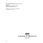
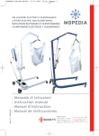
!
!
!
TREADMILL!MCB!CODE!SHEET!
Model!#!F9621***!!
!
!
!
Symbol
Description
Actions
Relay Position Abnormal
Usually accompanied by an Error 54
on the Display
Change Motor Control Board
Normal Operation – Relay is closed
Don’t do anything!
“Eight is Great” or “B is Beautiful”
Default Position when Relay
on MCB is open and waiting
for instruction.
Some errors cause the Relay to open, which then
causes ‘C’ to appear on the MCB. If the unit is not
operating and there is a ‘C’ on the MCB then there
should be an error on the display if it has power.
Speed Sensor Cable Error
(Error 53 appears on the Display)
ROM/PC Self Check error
Elevation Motor Error
Possibly Exceeding Range
Note: After changing an MCB or an
Elevation Motor an Elevation
Calibration must be completed.
!
!
Check that the speed sensor cable is
connected to the MCB on the connector
labeled “SPEED”. If not, attach it (Error C
appears on the LED) and reset the treadmill.
Check the speed sensor cable is not pinched.
* If the Speed Sensor light flashes when you
turn the motor but Error 53 still immediately
appears when the treadmill is turned on it could
be the R64 resistor on the MCB.
EPROM is correctly installed but it self-tested the
code and saw an error.
Most likely solution is a new EPROM.
Check the wire from the Elevation Motor is correctly
plugged in at the connector labeled “INCLINE”.
If it is not plugged in, the walking belt will run as
normal but when the user tries to increase or
decrease incline the value will change on the
screen but the elevation will not move.
If the wire is plugged in then Complete an Elevation
Calibration to see if the problem is solved.
If that doesn’t solve the problem, check the
resistance in OHMS (between the black and white
wires (not red) at the elevation connection) at the
maximum elevation (should be 450 Ohms) and
minimum elevation (850 Ohms)
!
Revision!1.1!+!Dec.9.13!
!
!
!
TREADMILL!MCB!CODE!SHEET!
Model!#!F9621***!!
!
!
!
Symbol
Description
Actions
Check Elevation Motor power wires are connected
Elevation Motor has a problem moving
correctly on the MCB.
If OK, then change the Elevation Motor.
Motor Power Circuit problem
Usually accompanied by an Error 52
on the Display
Change Motor Control Board
Data Cable or
Safety Key issue
If the Display has no power check if the Data Cable
is connected correctly or damaged.
If the Display has power, check if the Safety Key is
installed and then try to start the treadmill. If
“Please Put Safety Key” appears on the Display
then check the Reed Switch wiring is connected
correctly to the Display.
If the wiring is connected correctly then check the
Reed Switch is in the correct position inside the
console within range of the safety key magnet.
Check the reed switch is functioning correctly by
testing continuity on the reed switch.
The DC Voltage BUS is over its limit.
110V North American units should be
170 V DC so anything over 190 V DC
causes an Error “U”.
220V International units should be
350 V DC so anything over 380 V DC
causes an Error “U”
First, Check the AC power into the machine, it
should not exceed 125 V AC (N/A) or 240V AC
(International)
If the Power into the machine is OK then likely
solution is to change the Motor Control Board.
!
Revision!1.1!+!Dec.9.13!
!
!
!
!
TREADMILL!DISPLAY!ERROR!CODES!
Model!#!F9621****!
!
!
Error
Code
-
Description
Actions
PLEASE PUT SAFETY
KEY
Safety Key/Reed Switch
Error
Check if the Safety Key is correctly installed.
Check if the cable from the Reed Switch is correctly connected to the Display
Check if the Reed Switch is glued to the inside of the console and in the correct position so the safety
key magnet activates the switch from the outside correctly.
Check the Reed Switch (continuity) for a defect. Attach the safety key magnet to the switch and test.
Note: If the Data Cable has been pinched (during installation/moving the treadmill) you can
damage the Safety Key wire inside. The Safety Key error can occur if the other wires (power,
ground and data transfer) were not damaged but the safety key wire was. Test the Data Cable for
continuity or install a new data cable if you suspect this could have occurred.
51
Check if the Data Cable is connected to the MCB and Display correctly and the connectors are clean
and clear of debris, especially the connection at the MCB, which can get dusty.
If the connections are OK, then most of the time it is a problem with a pinched Data Cable that has
Communication problem
damaged one of the two communication wires inside (Data Transfer or Receive). Test the Data Cable
between the Display and
wires for continuity or install a new Data Cable to check.
the Motor Control Board.
Note: Data cables have 5 wires inside. 2 are for communication and if either of these are pinched then
an Error 51 will appear on the Display assuming the power (12V DC) and Ground (Green) wires are not
Tip: It is unlikely to have a damaged (if either of these are damaged the Display won’t light up as the circuit is open). The 5th wire
good EPROM and a bad
in the data cable is for the Safety key.
MCB and get Error 51.
Other Possibilities: Check the EPROM on the MCB as it could be inserted incorrectly (e.g. upside down)
or it could have damaged pins. If the software is corrupted it will also produce Error 51.
Less likely possibilities include a damaged MCB or a Display.
52
Tip: It is possible to get a
Turn the treadmill off (reset treadmill), wait a few seconds and turn it on. If ERROR 52 does not appear
False ERROR 52 on units
on screen, it is a false ERROR 52 caused by a glitch in the MCB software. A software update is
manufactured BEFORE
required as it CAN NOT be done via EPROM. Therefore order a new MCB with the software preFeb, 2013 due to a software
installed. If the Error 52 is still on screen then move onto the next suggestions.
error.
Revision!1.1!+!Dec!5,13!
!
Error
Code
Description
Actions
Check the motor wires (+ & -) are correctly attached to the MCB. Test.
On units manufactured
before Feb, 2013, Error 52
could be caused by an
Open Circuit detected from
the Motor on the MCB
(called Error 57 on units
built after Feb, 2013) or a
short circuit on the MCB.
Check if there is a P on the
MCB’s LED window. If so
this confirms a short.
52
Quick Motor Functionality Test using a 9V Battery:
Remove the Drive Belt that is connected to the Drive Motor Pulley so the motor can turn easily.
Remove the Motor Wires and connect a 9V battery to the positive and negative connectors. When the
motor wires make contact with the battery terminals the motor should spin.
Thorough Motor Test:
Place a multimeter pin in each motor wire connector and check the resistance.
You should get a reading between 0.9 & 1.6 OHMS. If you get a slightly lower or higher reading then
turn the flywheel a small amount and test again. A slightly higher or lower reading can be caused if the
reading was taken between poles (e.g. lower than 0.9 or up to 4 ohms). If you get “OL” (Overload) on
the multimeter then you have an open circuit in the motor and will likely have it in every position you try
to take a reading. The above-mentioned Quick Motor Functionality Test would fail if you have an open
circuit. You need to confirm if the “OL” is being caused by the Motor Brushes not making contact with
the commutator or an error inside the motor.
Check the Motor Brushes are making good contact with the commutator then it is possible that the
circuit has been opened inside the motor causing the “OL” which requires a motor change.
Note: YOU MUST
complete a thorough
Motor Test to see if it is
If you get a correct reading between 0.9 and 1.6 Ohms with the 1st reading then continue to test the
damaged and causing the
motor in 11 more position. Rotate the motor flywheel (e.g. from 12 o-clock to 1 o-clock) and ensure the
short in the MCB. If a
flywheel comes to a complete stop and take another reading. After each reading rotate the flywheel to
damaged motor is
the next position, stop, then take another reading. A good motor will have all the readings (except if
causing the MCB to short
between poles) between 0.9 and 1.6 Ohms. A bad motor may have a lot of readings outside the range.
and you install a new
MCB without changing
Check if the Motor Brushes are touching the commutator. Are they worn? If so, clean with fine
the motor then the new
sandpaper and reinsert. Test. You may need to replace the Motor Brushes.
MCB will short
immediately.
IMPORTANT: You must check if the MCB failure was caused by a short in the motor (see above
instructions) or
Change Motor Control Board
Most likely problem for Error 52 is that it is a Short Circuit on one of the power transistors (MOSFET) on
the MCB
Revision!1.1!+!Dec!5,13!
!
Error
Code
53
Description
Actions
Look to see if there is a “d” on the MCB. If so, the issue is likely with the speed sensor cable. Check
connection of cable and refer to MCB error code sheet.
If there is a “8” or a “C” on the MCB check the following.
Speed Sensor does not get
Check there is nothing jammed in the rollers or under the treadmill causing the belt to be jammed or
a continuous reading from
stuck.
the motor for 5 seconds or
Check the position of the Speed Sensor. It should be positioned around the optic disc. Is the Speed
the speed sensor is getting
Sensor bracket bent or misaligned? If so, loosen the screws on the motor that is holding the speed
a reading far below what is
sensor bracket and reposition it then tighten the screws firmly and test.
on the console.
Confirm Speed Sensor is reading correctly by turning the power on and manually turning the motor
flywheel so the optic disc spins. If the speed sensor is reading correctly then the Speed Sensor LED on
the MCB will flash as it takes a reading between each segment of the optic disc.
54
The Relay on the MCB is
signaling that it is closed
when it should be open.
Defective Relay on the MCB. An “A” on the MCB ‘s LED confirms this.
Change Motor Control Board.
55
Hardware current limit has
been exceeded for a very
short period of time.
This means that there is too much current but not high enough to represent a short-circuit which would
create an Error 52.
This can be created by holding back the running belt. Check that nothing is jamming the walking belt,
rollers, drive belt or motor from turning.
A defective component on the MCB may also cause this and therefor change the MCB.
Belt Speed Incorrect
If the actual belt speed is less than 80% or more than 120% of the required speed for more than 5
seconds then an Error 56 will appear.
e.g. if the required speed is 5 mph, then an Error 56 will appear if the actual speed reading is less than
4.0mph or greater than 6.0mph. (+ or -20% for 5 seconds)
Check if something is causing the walking belt, rollers, drive belt or motor from turning.
If not, it is likely a fault on the MCB and needs to be changed.
56
Revision!1.1!+!Dec!5,13!
!
57
100
Error 57 is caused by an
Check the motor wires (+ & -) are correctly attached to the MCB.
Open Circuit detected from
Check if the motor brushes are touching the commutator. Are they worn? If so, clean with fine
the Drive Motor on the MCB sandpaper and reinsert. Test. You may need to replace the motor brushes. Use a 9V battery to test the
(ONLY found on units
motor. Remove the Drive Belt that is connected to the Drive Motor Pulley and place the motor wires on
manufactured AFTER Feb, the battery terminals, the motor should spin. The motor will not spin if you have not removed the Drive
2013. On units
Belt.
manufactured before Feb,
Check the resistance of the motor by using a Multimeter. Place one pin in each motor wire connector.
2013, this error would show You should get a reading between 1 & 2 OHMS. If you get an extremely high reading on the Multimeter
as an Error 52.)
or the letters “OL” (Overload), there is a problem with the motor.
Standard Code for an
unrecognizable Error from
the MCB
No diagnosis possible – Change Motor Control Board
!
Revision!1.1!+!Dec!5,13!
!
!
HOW!TO!ALIGN!A!TREADMILL!WALKING!BELT!
ALL!TREADMILLS!
Model!#!F9611****!&!F9621****!
!
!
REQUIRED
TOOLS
Hex Key
Rear Roller
Screw
If the walking belt is not centered and is running to one side then it needs to be
realigned before it hits the foot rails and permanently damages the belt.
Frayed belts damaged from hitting the foot rail are not covered by the parts
warranty, as it is considered user error.
WARNING – Do not stand on the belt during this procedure and keep loose
clothing and long hair away from the belt and rollers.
NOTE – During the belt alignment procedure you may be required to make
several minor 1/4-turn adjustments to the rear roller screws. Never turn a
single screw more than 1 full revolution clockwise in total. Exceeding this may
over tighten the walking belt and cause a high amount of tension that can
result in premature wear of the belt, roller and motor. To prevent this problem,
it is best to adjust only one alignment bolt to centre the walking belt.
To adjust the walking belt alignment:
1. Enter the DIAGNOSTICS Menu and select BELT
ALIGNMENT (For a T240S-T280S-T520S: select “d2”)
and press JustGoTM to accept.
2. Allow the belt to reach 2.0 mph or 3.2 km/h. Stand at the
rear of the treadmill and note the gap between the right
and left sides of the belt (A) and the foot rails (B).
If the running belt is tracking (moving) to the left turn
the left rear roller screw (B) clockwise or turn the right
rear roller screw (B) counter-clockwise to allow the belt to
track to the right and towards the centre.
If the running belt is tracking (moving) to the right
turn the left rear roller screw (B) counter-clockwise or the
right rear roller screw (B) clockwise to allow the belt to
track to the left towards the centre.
3. WALKING BELT ALIGNMENT VERIFICATION
In order to verify that the running belt is aligned correctly, slowly increase the speed to a
maximum of 6.0 mph or 9.6 km/h, and let the belt turn for a least one (1) minute. Carefully
observe that the belt stays centered. If it does, move on to the next step.
However, if the walking belt continues to track to one side, or you hear a rubbing noise (the
belt may be touching the foot rails), immediately press the STOP key to stop the belt. You
will need to complete the alignment procedure again.
4. WALKING BELT TENSION VERIFICATION
Finally you need to confirm that the walking belt tension is correct. Start the treadmill and
begin walking on the belt. Slowly increase the speed to 2.0 mph or 3.2 km/h and check to
see that the belt runs smoothly and does not pause or stop each time you plant your foot. If
the belt does run smoothly, gradually increase the speed all the way to the maximum to
confirm that the tension is correct for all speeds. If at any time during this process the belt
does hesitate, stop the treadmill and TURN BOTH of the rear roller screws exactly ¼-turn
clockwise, which tightens the belt and restart the walking belt tension verification.
May.!17.!2012!
!
HOW!TO!COMPLETE!AN!INCLINE!CALIBRATION!
2012314!TREADMILLS!
Model!#!F9621****!
!
!
WARNING – Do not stand on the belt during this procedure. If the incline calibration is
interrupted, do not use the treadmill. It is important to fully complete the incline calibration
procedure again before using the treadmill.
2012 T260P, T280P, T460XC, T520P, T560X
1. Enter the Diagnostics menu by pressing and holding the iTek button for 3 seconds.
2. You have correctly accessed the Diagnostics menu when you see DIAGNOSTICS on
screen and a scrolling message: “TXXX VERSION”.
3. Use the SPEED INCREASE & DECREASE keys to scroll through the Diagnostics menu
until ELEVATION CALBRATION is on screen.
4. Press the Just Go key twice to begin the Elevation Calibration
5. Once you see “COMPLETE” on the display, press the “Stop” key 4 times to return to the
“Welcome Screen”. Your treadmill is ready to go.
2012 T240S, T240S0, T260P, T280S, T280PO, T460XC, T520P, T560X
1. Remove the motor cover.
2. Locate the Incline Calibration button labeled “INCLINE”. It is
directly below the EPROM and above the LED Display on the
left side of the board. (See picture to right.)
3. Press and hold the button down for 3 seconds. The platform
will start elevating. As soon as the platform begins elevating,
release the button and the calibration will perform on its own (it
will last about 1 minute).
4. When the calibration is completed, start the unit and test the
speed and incline function correctly.
1. Reinstall the motor cover onto the treadmill.
Feb.%2.%2012%