1
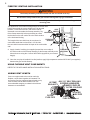
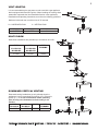
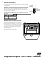
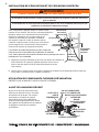
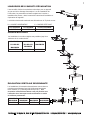
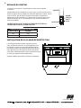
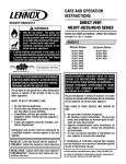
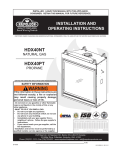
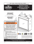
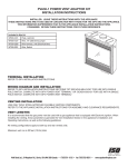
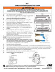
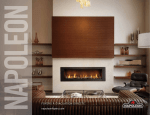
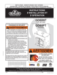
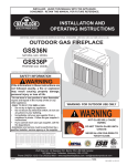
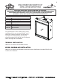
1
PVA40 POWER VENT ADAPTOR KIT
INSTALLATION INSTRUCTIONS
INSTALLER: LEAVE THESE INSTRUCTIONS WITH THE APPLIANCE.
THESE INSTRUCTIONS ARE TO BE USED IN CONJUNCTION WITH THOSE FOR THE GPV AND (C)HDX40.
THIS INFORMATION SUPERSEDES THAT IN THE (C)HDX40 INSTALLATION INSTRUCTIONS.
CONSUMER: RETAIN THESE INSTRUCTIONS FOR FUTURE REFERENCE.
Included in this kit:
W010-1777
Assembly, firestop spacer
W175-0309
Connector, reducer 5/8” to 4/7”
W500-0420
Plate, electrical box cover
W660-0078
Double pole switch
W750-0127
Wire, 14” jumper
W750-0197
Wire harness, unit
W750-0211
Wire, thermostat
The (C)HDX40 uses 5” and 8” flexible venting. When
installing the GPV for use with the (C)HDX40, the 4”/7”
reducer (W175-0309) is required. The reducer must
be properly secured and sealed to unit using high
temperature sealant W573-0007 Mill Pac (not supplied)
before continuing with vent installation.
TERMINAL INSTALLATION
REFER TO GPV INSTALLATION INSTRUCTIONS
WIRING DIAGRAM AND INSTALLATION
REFER TO GPV INSTALLATION INSTRUCTIONS SECTIONS “DEXEN 6003-3V COMPLETE WITH GPV
POWER VENT TERMINAL”
Wolf Steel Ltd., 24 Napoleon Rd., Barrie, ON L4M 4Y8 Canada • (705)721-1212 • fax (705)722-6031 •
www.napoleonfireplaces.com
2
FIRESTOP VENTING INSTALLATION
!
WARNING
The firestop assembly must be installed with the vent shield to the top.
Do not fill the cavity between the pipe and the framing with any type of material.
Terminals must not be recessed into a wall or siding more than the depth of the return flange of the
mounting plate.
This application occurs when venting through an exterior wall.
Having determined the correct height for the air terminal
VENT
location, cut and frame a hole in the exterior wall as
SHIELD
illustrated to accommodate the firestop assembly. Dry
CAULKING
fit the firestop assembly before proceeding to ensure
the brackets on the rear surface fit to the inside surface
of the horizontal framing.
FIRESTOP
SPACER
The length of the vent shield may be cut shorter for
combustible walls that are less than 8 1/2” thick but
the vent shield must extend the full depth of the combustible
wall.
A. Apply a bead of caulking (not supplied) around the corner edge of
the inside surface of the firestop assembly, fit the firestop assembly to the
hole and secure using the 4 screws W570-0026 (supplied in your manual
baggie).
11 3/8”
9 7/8”
DETERMINE
THE
CORRECT
HEIGHT
FINISHING
MATERIAL
B. Once the vent pipe is installed in its final position, apply high temperature sealant W573-0007 (not supplied)
between the pipe and the firestop.
USING FLEXIBLE VENT COMPONENTS
REFER TO THE APPLIANCE INSTALLATION INSTRUCTIONS
ADDING VENT LENGTH
If more vent pipe needs to be used to reach the
fireplace, couple them together as illustrated. The
vent system must be supported approximately every
3 feet for both vertical and horizontal runs. Use
noncombustible strapping to maintain the minimum
clearance to combustibles.
HI-TEMP
SEALANT
OUTER
FLEX PIPE
#8 X 1/2” SELF DRILLING
SCREWS & WASHERS
INNER COUPLER
OUTER COUPLER
OUTER
FLEX PIPE
INNER
FLEX PIPE
Wolf Steel Ltd., 24 Napoleon Rd., Barrie, ON L4M 4Y8 Canada • (705)721-1212 • fax (705)722-6031 •
www.napoleonfireplaces.com
3
VENT LENGTHS
It is recommended that the gas power vent be used with a gas appliance
that is equipped with Electronic Ignition. When installing the venting, these
parameters supersede the Vent Installation Section in the appliance's
Installation and Operating Instructions, as well as the following guidelines:
Maximum horizontal vent run with no rise is 70 feet total.
H = HORIZONTAL RUN
V = VERTICAL RUN
MAX H+V
MIN H+V
MAX ELBOWS
70 FEET
10 FEET
SIX 90°
MULTI ELBOW
Multi-elbow installations are possible up to a maximum of six 90°.
MAX
MIN
V1+V2+V3+
V1+V2+V3+
H1+H2+H3
H1+H2+H3
70 FEET
10 FEET
MAX
ELBOWS
SIX 90°
DOWNWARD VERTICAL VENTING
Downward venting installations are only allowed when the
appliances is set to Intermittent Pilot Ignition (I.P.I.) Electronic
Ignition (E.I.). If an anti-condensation switch (standing
pilot) is being used, downward vertical venting is not
allowed.
MAX
MIN
MAX D
MAX
H1+H2+V
H1+H2+V
ELBOWS
70 FEET
10 FEET
8 FEET
SIX 90°
Wolf Steel Ltd., 24 Napoleon Rd., Barrie, ON L4M 4Y8 Canada • (705)721-1212 • fax (705)722-6031 •
www.napoleonfireplaces.com
4
VENTURI ADJUSTMENT
This appliance has an air shutter that has been factory set open according
to the chart below:
Regardless of venturi orientation, closing the air shutter will cause a more
yellow flame, but can lead to carboning. Opening the air shutter will cause a
more blue flame, but can cause flame lifting from the burner ports. The
flame may not appear yellow immediately; allow 15 to 30 minutes for the
final flame color to be established.
VENTURI
BURNER
AIR
SHUTTER
OPENING
ORIFICE
AIR SHUTTER ADJUSTMENT MUST ONLY BE DONE BY A QUALIFIED
INSTALLER!
49.1
VENTURI ADJUSTMENT CHART
FUEL
(C)HDX40
NG
3/16”
LP
7/16”
RESTRICTOR PLATE INSTALLATION
Vertical terminations may display a very active flame. If
this appearance is not desirable, the vent exit must be
restricted using restrictor plate, W500-0205 (supplied with
unit). This reduces the velocity of the exhaust gases,
slowing down the flame pattern and creating a more
traditional appearance.
Install the plate over the exhaust outlet.
W415-0902 / 03.24.10
Wolf Steel Ltd., 24 Napoleon Rd., Barrie, ON L4M 4Y8 Canada • (705)721-1212 • fax (705)722-6031 •
www.napoleonfireplaces.com
5
INSTRUCTIONS D’INSTALLATION DE LA
TERMINAISON MÉCANIQUE PVA40
INSTALLATEUR : LAISSEZ CE MANUEL AVEC L’APPAREIL.
CES INSTRUCTIONS DOIVENT ÊTRE UTILISÉES CONJOINTEMENT AVEC CELLES DU GPV ET DU (C)HDX40.
CES INFORMATIONS REMPLACENT LES INSTRUCTIONS D’INSTALLATION DU (C)HDX40.
PROPRIÉTAIRE : CONSERVEZ CE MANUEL POUR CONSULTATION ULTÉRIEURE.
Cet ensemble comprend :
W010-1777
Assemblage de l’espaceur coupe-feu
W175-0309
Raccord, réducteur de 5/8” à 4/7”
W500-0420
Plaque, couvercle du boîtier électrique
W660-0078
Interrupteur bipolaire
W750-0127
Fil de connexion de 14”
W750-0197
Harnais de fils
W750-0211
Fil du thermostat
Le (C)HDX40 utilise des conduits flexibles de 5” et de 8”.
Quand le GPV est installé pour être utilisé avec le HD50,
vous devez utiliser un réducteur 4”/7” (W175-0309). Le
réducteur doit être fixé et scellé à l’appareil avec du
scellant à haute température Mill Pac W573-0007 (non
fourni) avant de continuer l’installation de l’évacuation.
INSTALLATION DE LA TERMINAISON
RÉFÉREZ-VOUS AUX INSTRUCTIONS D’INSTALLATION DU GVP.
SCHÉMA DE CÂBLAGE ET INSTALLATION
VOIR LES INSTRUCTIONS D’INSTALLATION DU GPV, SECTIONS « SOUPAPE DEXEN 6003-3V AVEC
TERMINAISON À ÉVACUATION MÉCANIQUE GPV ».
Wolf Steel Ltd., 24 Napoleon Rd., Barrie, ON L4M 4Y8 Canada(705)721-1212 • télécopieur(705)722-6031 • www.napoleonfoyers.com
6
INSTALLATION DE L’ÉVACUATION ET DE L’ESPACEUR COUPE-FEU
!
AVERTISSEMENT
L’espaceur coupe-feu doit être installé avec l’écran protecteur orienté vers le haut.
Ne remplissez l’espace entre le conduit d’évent et le manchon de l’espaceur coupe-feu avec aucun
type de matériau.
Les terminaisons ne doivent pas être enchâssées dans le mur ou le revêtement extérieur plus que
l’épaisseur de la bride de la plaque de montage.
Cette configuration s’applique lorsque le conduit d’évent
PROTECTEUR
DE CONDUIT
traverse un mur extérieur. Une fois que vous aurez déterminé
D’ÉVACUATION
la hauteur exacte pour l’emplacement de la terminaison,
découpez et charpentez une ouverture dans le mur
CALFEUTRAGE
extérieur tel qu’illustré pour permettre l’installation
de l’espaceur coupe-feu. Avant de continuer, placez
l’espaceur coupe-feu dans l’ouverture pour vous assurer
ESPACEUR
que les supports sur la surface arrière soient placés à
COUPE-FEU
l’intérieure de la pièce de charpente horizontale.
Le protecteur de conduit d’évacuation peut être coupé plus
court pour les murs combustibles dont l’épaisseur est moins de
8 1/2” mais le protecteur de conduit d’évacuation doit se prolonger sur toute la
profondeur du mur combustible.
11 3/8”
9 7/8”
DÉTERMINEZ
LA BONNE
HAUTEUR
MATÉRIAU
DE FINITION
A. Appliquez un joint de calfeutrage (non fourni) tout autour de la bordure de
la face intérieure de l’espaceur, installez l’espaceur dans le trou et
fixez à l’aide des quatre vis W570-0026 (fournies dans le sac de
votre manuel).
B. Une fois que le conduit d’évent est en place, appliquez du scellant à haute température W573-0002 (non
fourni) entre le conduit d’évent et l’espaceur coupe-feu.
UTILISATION DE COMPOSANTS FLEXIBLES D’ÉVACUATION
RÉFÉREZ-VOUS AU MANUEL D’INSTALLATION DE L’APPAREIL
AJOUT DE LONGUEUR D’ÉVENT
Si plus de sections de gaine doivent être
utilisées pour atteindre le foyer, raccordezles ensemble tel qu’illustré. Les courses
horizontales et verticales du système
d’évacuation doivent être supportées à
chaque 3 pieds approximativement. Utilisez
des supports incombustibles afin de maintenir
le dégagement minimal aux matériaux
combustibles.
SCELLANT À
HAUTE
TEMPÉRATURE
VIS AUTO-PERCEUSES
#8 X 1/2” ET RONDELLES
BAGUE D’ACCOUPLEMENT
INTÉRIEURE
BAGUE
D’ACCOUPLEMENT
EXTÉRIEURE
GAINE FLEXIBLE
EXTÉRIEURE GAINE
GAINE FLEXIBLE
EXTÉRIEURE
FLEXIBLE INTÉRIEURE
Wolf Steel Ltd., 24 Napoleon Rd., Barrie, ON L4M 4Y8 Canada(705)721-1212 • télécopieur(705)722-6031 • www.napoleonfoyers.com
7
LONGUEURS DES CONDUITS D’ÉVACUATION
Il est conseillé d’utiliser la terminaison mécanique avec un appareil
au gaz muni d’un allumage électronique. Lors de l’installation de
l’évacuation, les paramètres suivants remplaceront la section «
Installation des évents » dans le manuel d’instructions d’installation et
d’opération de l’appareil :
La déviation horizontale maximale sans élévation est de 70 pieds en tout.
H = COURSE HORIZONTALE
V = COURSE VERTICALE
H+V MAXIMUM
H+V MINIMUM
COUDES MAXIMUM
70 PIEDS
10 PIEDS
SIX 90°
COUDES MULTIPLES
Les installations à coudes multiples sont possibles jusqu’à un
maximum de six coudes de 90°.
V1+V2+V3+
V1+V2+V3+
COUDES
H1+H2+H3
H1+H2+H3
MAXIMUM
MAXIMUM
MINIMUM
70 PIEDS
10 PIEDS
SIX 90°
ÉVACUATION VERTICALE DESCENDANTE
Les installations d’évacuations descendantes sont seulement
permises quand l’appareil est réglé à Allumage intermittent
de la veilleuse (I.P.I.) Allumage électronique (E.I.). Une
évacuation verticale descendante n’est pas permise avec
l’utilisation d’un interrupteur anticondensation en mode
de veilleuse permanente.
H1+H2+V
MAXIMUM
H1+H2+V
MINIMUM
D
MAXIMUM
COUDES
MAXIMUM
70 PIEDS
10 PIEDS
8 PIEDS
SIX 90°
Wolf Steel Ltd., 24 Napoleon Rd., Barrie, ON L4M 4Y8 Canada(705)721-1212 • télécopieur(705)722-6031 • www.napoleonfoyers.com
8
RÉGLAGE DU VENTURI
L’ouverture du volet d’air a été préréglée en usine selon le tableau
ci-dessous.
VENTURI
Indépendamment de l’orientation du venturi, plus le volet est fermé, plus la
flamme est jaune et aura tendance à causer des dépôts de carbone. Plus le
volet est ouvert, plus la flamme est bleue et plus elle a tendance à se
détacher des orifices du brûleur. La flamme peut ne pas être jaune immédiatement; allouez de 15 à 30 minutes pour que la couleur finale de la
flamme se stabilise.
INJECTEUR
OUVERTURE DU
VOLET
D’AIR
LE RÉGLAGE DU VOLET D’AIR DOIT ÊTRE EXÉCUTÉ PAR UN
TECHNICIEN OU INSTALLATEUR QUALIFIÉ!
49.1
TABLEAU DU RÉGLAGE DU VENTURI
COMBUSTIBLE
(C)HDX40
GN
3/16”
PL
7/16”
INSTALLATION DE LA PLAQUE DE RESTRICTION
Les configurations d’évacuation verticales peuvent
avoir une flamme très active. Si cette apparence n’est
pas désirée, la sortie de l’évacuation doit être réduite
en utilisant la plaque de restriction W500-0205 (fournie
avec l’appareil). Ceci diminuera la vélocité des gaz de
combustion, ralentissant ainsi le mouvement de la flamme
et créant une apparence plus traditionnelle.
Installez la plaque par-dessus la sortie de l’évacuation.
W415-0902 / 03.26.10
Wolf Steel Ltd., 24 Napoleon Rd., Barrie, ON L4M 4Y8 Canada(705)721-1212 • télécopieur(705)722-6031 • www.napoleonfoyers.com